Table of Contents
Advertisement
Advertisement
Table of Contents
Troubleshooting

Related Manuals for Stairmaster GAUNTLET Series 8


Summary of Contents for Stairmaster GAUNTLET Series 8
- Page 1 Core Health & Fitness 8 Series Gauntlet SERVICE MANUAL...
-
Page 2: Table Of Contents
TABLE OF CONTENTS Click any text to jump to section ..................1 Title Page and Table of Contents SAFETY INFORMATION ............................. 3 ..................5 Safety Instructions Important Label Locations ..................17 Terminology ..................19 PRODUCT SPOTLIGHT ............................20 INSTALLATION ............................21 PART IDENTIFICATION & THEORY ............................ -
Page 3: Safety Information
SAFETY INFORMATION the equipment, the club member should obtain a complete physical examination form their health care provider before beginning any exercise DANGER - to reduce the risk of electrical program. shock: This machine is not intended to be used by Always unplug the machine from the electrical children. - Page 4 Wear proper exercise clothing and athletic shoes during a workout. Avoid wearing loose clothing. Tie back long hair and keep towels away from the moving parts. Face forward at all times and never attempt to turn around while the machine is moving.
-
Page 5: Safety Instructions
Safety Instructions This chapter includes precautions and fitness safeguards for the installation and use of the product. Please read this chapter carefully before installing or using your equipment. Safety instructions are provided in the following languages (in the order shown): •... - Page 6 PRECAUTIONS CAUTION: READ THE OWNER’S CAUTION: MOVING PARTS, KEEP MANUAL COMPLETELY BEFORE HANDS AND FEET FROM UNDER OPERATING THIS MACHINE. THE STAIRMILL WHEN OPERATING. CAUTION: BEFORE CLEANING OR SERVICING, DISCONNECT POWER STOP (OF ACTIVITY) SUPPLY. These safety notes are directed to you as the owner of the equipment. For safety purposes, it is your responsibility to train all your members and fitness staff to follow these safety instructions.
- Page 7 VOORZORGSMAATREGELEN WAARSCHUWING: LEES DE WAARSCHUWING: BEWEGENDE GEBRUIKERSHANDLEIDING ONDERDELEN, HOUD HANDEN VOLLEDIG VOORDAT UDIT TOESTEL EN VOETEN NIET ONDER HET IN GEBRUIKT NEEMT. TOESTEL TIJDENS GEBRUIK. WAARSCHUWING: HAAL DE STEKKER UIT HET STOPCONTACT STOP (ACTIVITEIT) VOORDAT U HET TOESTEL REINIGT OF ONDERHOUDT. Deze veiligheidsmaatregelen zijn aan u als eigenaar van de apparatuur gericht.
- Page 8 PRÉCAUTIONS MISE EN GARDE : PRENDRE MISE EN GARDE : PIÈCES MOBILES MARCHE CONNAISSANCE DU MODE ; NE PAS METTRE LES MAINS NI D’EMPLOI AVANT DE SE SERVIR LES PIEDS EN DESSOUS DE ARRÊT DE L’APPAREIL. L’APPAREIL LORSQU’EN FONCTIONNEMENT. MISE EN GARDE : DÉBRANCHER L’APPAREIL DU SECTEUR AVANT ARRÊT (DE L’ACTIVITÉ) TOUTE PROCÉDURE DE...
- Page 9 PRECAUZIONI ATTENZIONE: PRIMA DI UTILIZ- ATTENZIONE: PRESENZA DI PARTI ZARE LA MACCHINA LEGGERE IL IN MOVIMENTO, TENERE MANI MANUALE DI ISTRUZIONI. E PIEDI LONTANI DALLA PARTE INFERIORE DELLA MACCHINA MENTRE QUESTA È IN FUNZIONE. ATTENZIONE: PRIMA DI EFFETTUARE LA PULIZIA O INTERVENTI DI ARRESTO (DELL’ATTIVITÀ) MANUTENZIONE, TOGLIERE TENSIONE ALLA MACCHINA.
- Page 10 PRECAUÇÕES CUIDADO: LEIA POR COMPLETO CUIDADO: PARTES MÓVEIS, LIGA O MANUAL DO PROPRIETÁRIO MANTENHA AS MÃOS E OS PÉS ANTES DE OPERAR ESTA AFASTADOS DA PARTE SOB A DESLIGA MÁQUINA. MÁQUINA DURANTE A OPERAÇÃO. CUIDADO: ANTES DA LIMPEZA OU MANUTENÇÃO, DESCONECTE A PARADA (DA ATIVIDADE) ALIMENTAÇÃO.
- Page 11 PRECAUCIONES CUIDADO: LEA COMPLETAMENTE CUIDADO: CUENTA CON PARTES ENCENDIDA EL MANUAL DEL PROPIETARIO MÓVILES, AL OPERARLA ANTES DE OPERAR ESTA MANTENGA LAS MANOS Y PIES APAGADA MÁQUINA. ALEJADOS DE DEBAJO DE LA MÁQUINA. CUIDADO: ANTES DE LIMPIAR O DAR SERVICIO, DESCONECTE EL DETENER (EL FUNCIONAMIENTO) SUMINISTRO DE ENERGÍA.
- Page 12 FÖRSIKTIGHETSÅTGÄRDER VARNING: LÄS HELA VARNING: DET FINNS RÖRLIGA PÅ ÄGARHANDBOKEN INNAN DU DELAR. HA INTE HÄNDER ELLER ANVÄNDER DEN HÄR MASKINEN. FÖTTER UNDER MASKINEN NÄR DEN ANVÄNDS. VARNING: kOPPLA UR ELKABELN FÖRE RENGÖRING OCH STOPPA (AKTIVITETEN) UNDERHÅLL. Dessa säkerhetsföreskrifter är riktade till dig som är ägare av utrustningen. Av säkerhetsskäl är det ditt ansvar att utbilda alla medlemmar och träningspersonal så...
- Page 13 预防措施 注意:操作机器前请通读用户手 注意:活动部件,操作时请将手 开启 册。 脚远离机器下方。 关闭 注意:清洗或维修前,请断开电 源。 停止(活动) 这些安全须知专为机器所有者编写。安全起见,您应负责培训所有会员及健身教练,使之遵守相关安全说明。 应做事项 禁止事项 在开始任何锻炼项目之前通知会员进行健康检 请勿让儿童操作机器。病人或残疾人士使用机器 • • 查。使用 过 程 中如出现头晕目眩或疼痛感,请 时需有 人监管。 立即停止并咨询 医生 请勿超过使用者体重的最大容许值 350 磅/159 • 使用前请务必通读、理解并严格遵守机器及本手 千克)。 • 册上的 所 有警告、说明及程序。 请勿在未穿运动鞋时使用机器。 • 仅可将该机器用于本手册所述的预期用途。 • 使用机器时,请勿穿着宽松、悬垂的衣物。 •...
- Page 14 使用上の注意 注意:本機を操作する前に、取 注意:本機の稼働中は、可動部 オン 扱説明書全体に目を通してくだ に注意し、本体の下側に手足を さい。 差し込まないでください。 オフ 注意:清掃や保守を行う前に、電 源を切断してください。 エクササイズの)中止 これらの安全上の注意は、機器の所有者に向けられています。安全手順が守られるよう、すべてのフィットネス会 員やスタッフにトレーニングを提供することは所有者の責任です。 次のことを確実に実施してください。 次のことは絶対に避けてください。 子供達に本機を操作させる。病人や障害者に本 • 何らかのエクササイズ プログラムを開始する前に、健 康診 • 機を使 用させる。 断を受けるよう会員に促す。運動中にめまい、脱力 感、痛み 159 kg(350 ポンド)の最大許容体重を超え • などを感じた場合は、ただちに使用を停止して 医師に相談す る。 る。 運動靴を履かずに本機を使用する。 • 本機上に貼られていたり、本取扱説明書に含まれていた りす • ぶかぶかな服や、垂れている服を着て本機を使 •...
- Page 15 ПРАВИЛА ТЕХНИКИ БЕЗОПАСНОСТИ ВНИМАНИЕ. ПЕРЕД ВНИМАНИЕ. ДВИЖУЩИЕСЯ ВКЛ. ИСПОЛЬЗОВАНИЕМ ТРЕНАЖЕРА ЧАСТИ - УБИРАЙТЕ РУКИ И ВНИМАТЕЛЬНО ПРОЧИТАЙТЕ НОГИ ИЗ-ПОД ТРЕНАЖЕРА ПРИ ВЫКЛ. РУКОВОДСТВО ПОЛЬЗОВАТЕЛЯ. ЭКСПЛУАТАЦИИ. ВНИМАНИЕ. ПЕРЕД ОЧИСТКОЙ ИЛИ ОБСЛУЖИВАНИЕМ ОСТАНОВ (РАБОТЫ) ТРЕНАЖЕРА ОТКЛЮЧИТЕ ЕГО ОТ ИСТОЧНИКА ПИТАНИЯ. Настоящие примечания по технике безопасности предназначены для вас как для владельца тренажера. В целях безопасности...
- Page 16 ARABIC SAFETY INSTRUCTIONS Page 16...
-
Page 17: Important Label Locations
Important Label Locations READ THE OWNERS MANUAL AND FOLLOW ALL PROPER INSTRUCTIONS PRIOR TO USE. IMPROPER USE OF THIS MACHINE CAN RESULT IN SERIOUS INJURY. 1. As with all exercise equipment or programs, consult a physician prior to use and stop if you feel faint, dizzy or exhausted. -
Page 18: Regulatory Information
Regulatory Information CANADIAN DOC AND OTHER REGULATIONS This section provides regulatory and safety information This class A digital apparatus meets all requirements of pertaining to the product the Canadian Interference Causing Equipment Regulations. This product has also been tested to meet FCC AND OTHER DOMESTIC the following standards: REGULATIONS... -
Page 19: Terminology
Terminology Concept Description Current The number of electrically charged particles that flow past a given point on a circuit in a given time Ampere (AMP) A measure of current Volt (V) Measures the difference of the current pressure of a circuit. Core refers to the 2 most common global voltages as: •... -
Page 20: Product Spotlight
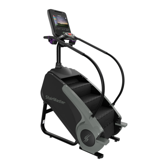
PRODUCT SPOTLIGHT Beginning with the first stepping machine in 1983, StairMaster® has been a legendary name in the gym. Today the tra- dition continues with the Gauntlet®. Building on 30 years of experience and proven performance, the Gauntlet provides a superior combination of cardio and strength training in our most comfortable design ever. The machine features a deeper, wider step surface with durable, rust-free polypropylene construction and is now available with all three smart, affordable, flexible, OpenHub™... -
Page 21: Installation
INSTALLATION Caution: The unit is very heavy. Two people may be needed to move the frame assembly. Remove all the packaging material and parts not attached to unit including shrouds, mast, hardware card, etc. so the 8G Stepmill is ready for assembly on the shipping crate platform. - Page 22 Secure the Frame Neck Adapter to the frame using four (4) pieces each of the 5/16”x1 3/4” screws, 21mm OD washers, and 5/16” nylok hex nut. Slide the Mast Grommet onto the mast first and then the Upper Shroud Cover Route the wires for the display up and out through the top of the mast.
- Page 23 Slide the Left Handrail Grommet onto the Lower Left Handrail then repeat this step for the Right Handrail Grommet and Lower Right Handrail. At- tach handrails with (2) pieces each of the 3/8”x1” screws and 3/8” nylok hex nuts and (4) pieces of the Ø3/8”...
- Page 24 Slide the upper shroud cover and neck grom- met down the mast onto the frame ensuring the grommet has a good seal between the mast and the upper shroud before securing using the plastic rivets on the inside of the frame. Attach the Lower Right Handrail Cover using the plastic rivets then repeat for the Lower Left Handrail.
- Page 25 Fasten the back half of the console assembly to the Mast using the screws supplied with the console. Connect the appropriate wires coming out of the mast to the correct locations, please reference the console wiring guide (CSB 620-8424). Secure the front half of the console assembly to the back half using the screws supplied with the console taking care not to pinch any wires and ensuring that the rubber console grommet has a...
- Page 26 Install Transport Wheels (Optional) The Transport Wheels can optionally be installed to help with movement of the unit. Slide a Transportation Pin through the left side of the frame. Then, slide one Transport Wheel onto the left side transportation pin so that the wheel sits inside the frame.
- Page 27 Installation is Complete Plug power into wall and perform final checks. Note: Be sure to set the display to correct model in the Maintenance Mode. Page 27...
-
Page 28: Part Identification & Theory
PART IDENTIFICATION & THEORY Resistance is applied to the steps of the machine by use of an alternator. 12VDC power from the lower board is fed into the alternator to control the amount of resistance it applies. The resistance system (alternator) connects the gearing system, or gear box of the machine via a poly-V belt. - Page 29 Gearbox Part Number: 711-3334 Brake Kit Part Number: 260-0958-KT Diagram Speed Sensor Part Number: 140-3501 • LCB Connection: J1 Page 29...
- Page 30 Alternator Assembly Part Number: 711-3361 • +3 Volts control input supplied to LCB • +12 Volts supplied from LCB • Provides resistance to the unit • Assembly may include alternator 260-0952 or SM22900. Wiring for both using harness 711-3351 is below. 260-0952 Alternator Wiring Blue to F Red to B+...
-
Page 31: Power System
Power enters the system through a power converter brick plugged into the wall. It runs through an EMI filter into the LCB where it is distributed to the rest of the system based on console signals. The LCB is also connected to a pair of load resistors. - Page 32 Connection Detail (Electrical) Main Data Cable Part Number: 711-3494 • LCB Connection: P1 Pinout with Diagram Page 32...
- Page 33 Alternator/EMI/Battery Cable Part Number: 711-3351 • LCB Connection: J2 Pinout with Diagram Power Input Cable Part Number: 711-3495 Pinout with Diagram Load Resistors Part Number: 711-3242 • LCB Connection: R1 Page 33...
- Page 34 Battery Part Number: 580-0275 (Order PN 800-3102) EMI Filter Part Number: 440-0282 Power Supply The external power supply is supplied with the unit and plugs into a standard 115 volt, 15 amp outlet, or a 220- 240 volt 50Hz, 10 amp outlet. All major voltage plugs are available.
-
Page 35: Step Hardware
The steps on the 8G are a composite plastic step with a rubber tread built into step top. The step top and kick plate are held together and to the step chains by step hinges, threaded step shafts, nylon spacers, bearings, washers, and bolts. As the steps rotate, bearings in the step shaft hardware ride down the rails on bearing plates. - Page 36 Step Riser Part Number: 050-0032 Step Hinge Shaft Part Number: 711-3326 Step Shaft Part Number: 711-3327 Page 36...
- Page 37 Hinge Clip Part Number: 140-3256 Inner Washer (2 per group) Part Number: 731-0294 Outer Washer Part Number: 120-0490 Bearing Part Number: 130-1660 Part Number: 110-3474 Bearing Plate Part Number: 711-3316 Hardware • Screw Part: 110-3140 • Part: 110-1871 Page 37...
-
Page 38: Drive System Hardware
The upper sprocket has an inner sprocket that connects the drive chain to the gear box sprocket. There is an idler arm and sprocket on the gear box to assist with keeping tension on the drive chain. The upper and lower sprockets are held to the chassis of the machine by pillow block bearings and connect the left-side and right-side step chains. - Page 39 Upper Sprocket Part Number: 711-3313 • Connects to the Gearbox via the Drive Chain on the inner sprocket Lower Sprocket Part Number: 711-3314 Poly-V Belt Part Number: 130-1784 Page 39...
- Page 40 Pillowblock Bearing Part Number: 130-1780 Hardware (Clockwise from Bearing) • Pillow Block Limiter Part: 711-3393 • Adjustment Screw Part: 110-2150 • Washer Part: 120-0410 • Adjustment Plate Part: 711-3312 • Washer Part: 120-0463 • Part: 110-1830 • Bolt Part: 110-3473 Page 40...
-
Page 41: Wiring And Power Flow
WIRING AND POWER FLOW Power wiring from external power supply to LCB The 8G uses a power brick to step down the wall voltage from 110/220 to 12V nominal. The 8G does not require a dedi- cated or 20A circuit, although a grounded outlet is required. Click on an icon to open the diagram in a new window. - Page 42 Power Tracing Variable (B+) 9-12V A power trace tests the voltage at every junction point of electricity on the machine from the wall to the console to validate good power flow and eliminate power as part of routine troubleshooting. Refer to the diagram above for the general flow of a power trace of the 8G.
-
Page 43: Signal Flow
SIGNAL FLOW All TV/Cable signals in the 8G are pass-through signals to the console. Coax cable for TV signals is plugged into the lower right leg of the 8G and connects to an internal coax cable that goes through the head to the console. The coax cable does not interact with the internal electrical components of the 8G. -
Page 44: Preventative Maintenance
PREVENTATIVE MAINTENANCE Preventive maintenance (PM) is a schedule of planned maintenance actions aimed at the prevention of failures. PM is the best way to preserve and enhance equipment reliability by keeping key com- ponents clean and free of debris. PM activities may include cleaning, vacuuming, visual inspections of key components, lubrication, etc. - Page 45 preventive maintenance routines outlined below. The safety and integrity of this machine can only be maintained when the equipment is regularly examined for damage and wear and repaired. It is the sole responsibility of the owner of this equip- ment to ensure that regular maintenance is performed. Worn or damaged parts must be replaced immediately or the equipment removed from service until the repair is made.
- Page 46 • Do not use glass cleaners or any other household cleaners on the console. As per the Preventative Maintenance schedule in the Owner’s Manual, the console should be cleaned with a damp cloth and dried on a daily basis. Cleaning solutions can be made of a 5:1 dilution ratio, where 5 parts water are mixed with 1 part of Simple Green®, Fantastik®, or 409®.
-
Page 47: Troubleshooting
TROUBLESHOOTING Find the issue relating to your console in the tables on the following pages. For a complete list of part replacement procedures unrelated to troubleshooting, see Part Replacement Procedures on page 53. Navigation On any Customer Service Bulletin you will see this navigation panel: Click the button to load the latest revision of the bulletin from our support site. - Page 48 Dispo. Power Issues Link Note Procedure (Internal) The unit won’t turn on 32347 Performing a Quickstart Test 32347 The hot bar buttons don’t respond to input at all 32347 The hot bar buttons only respond intermittently 32347 Performing a Power Trace 32347 See the facility power requirements for the 8G 32347...
- Page 49 For the latest software versions for products or to obtain other bulletins in regards to uploaders, uploading, download- ing software from the website to a PC and getting software from a PC into an Uploader, please check the Customer Services website.
- Page 50 Dispo. Mechanical Issues Link Note Procedure (Internal) The steps freewheel/have no resistance 32347 The 8G makes noise during use 32347 The brake on the unit makes a grinding/squeaking noise 32347 when not engaged Steps don’t move at all 32347 The alternator chain makes noise or is grinding when in 32347 use.
-
Page 51: Troubleshooting Procedures
Troubleshooting Procedures This page lists out all procedures embedded in this manual. Click the icon to open a procedure, and from within that procedure click the button to close it. Note: these buttons will not work in a browser window. Right click > Save As or click the button in your browser to save this manual to your PC. - Page 52 Document Title Doc. Ctrl. Rev. Procedure LCB Comm Lost 637-4297 OpenHub Heart Rate Test 637-4409 OpenHub Service Light Information 637-4293 Power Requirements 637-8490 Quickstart Test 637-4476 Random Hill Program Explained 637-8473 Slipping Brake 637-8505 Step Rate Issues 637-4522 Stepmill Alternator Belt Alignment 637-4278 Stepmill Noise Troubleshooting 637-4328...
-
Page 53: Part Replacement Procedures
Document Title Doc. Ctrl. Rev. Procedure Updating Software on Gauntlet w/LCD OpenHub Console 637-4277 Part Replacement Procedures This manual has the following step-by-step part replacement procedures embedded. For a procedure not listed, please contact Customer Support. Note: these buttons will not work in a browser window. Right click > Save As or click the button in your browser to save this manual to your PC. - Page 54 © 2017 CORE HEALTH & FITNESS, LLC PART NUMBER 620-8546, REV B...
Need help?
Do you have a question about the GAUNTLET Series 8 and is the answer not in the manual?
Questions and answers
Hello, can you help me by unifying me why it does not release the magnetic brake when starting and what is the solution. Thanks
The Stairmaster Series 8 may not release the magnetic brake when starting due to issues with the alternator, brake, or gearbox. One specific issue mentioned is that the brake audibly clicks when a workout is started, but step movement doesn’t begin or is extremely slow. This suggests the brake is not properly disengaging.
The solution involves checking the drive system, including the alternator assembly, brake kit, and gearbox. Ensure correct wiring of the alternator, proper power supply (+12V from LCB and +3V control input), and that components like the alternator and brake are functioning and properly connected. If any parts are misaligned, worn, or damaged, they should be adjusted or replaced.
This answer is automatically generated