Mitsubishi FX3U-20SSC-H User Manual
Melsec-f programmable controllers
Hide thumbs
Also See for FX3U-20SSC-H:
- User manual (304 pages) ,
- User manual (206 pages) ,
- Quick start manual (19 pages)
Table of Contents
Advertisement
Quick Links
Download this manual
See also:
User Manual
Advertisement
Table of Contents

Subscribe to Our Youtube Channel
Related Manuals for Mitsubishi FX3U-20SSC-H


Summary of Contents for Mitsubishi FX3U-20SSC-H
- Page 1 -20SSC-H USER'S MANUAL...
- Page 3 Safety Precautions (Read these precautions before using.) Before installing, operating, maintenance or inspecting this product, thoroughly read and understand this manual and the associated manuals. Also pay careful attention to handle the module properly and safety. This manual classifies the safety precautions into two categories: Indicates that incorrect handling may cause hazardous conditions, resulting in death or severe injury.
- Page 4 Safety Precautions (Read these precautions before using.) Reference • Fit the extension cables, peripheral device connecting cables, input/output cables and battery connecting cable securely to the designated connectors. Contact failures may cause malfunctions. • Use the product in the environment within the generic specifications described in section 3.1 of this manual. Never use the product in areas with dust, oily smoke, conductive dusts, corrosive gas (salt air, Cl S, SO ), flammable gas, vibration or impacts, or expose it to high temperature, condensation, or wind and rain.
- Page 5 • Do not disassemble or modify the PLC. Doing so may cause failures, malfunctions or fire. For repair, contact your local Mitsubishi Electric distributor. • Before connecting or disconnecting any extension cable, turn off power. Failure to do so may cause unit failure or malfunctions.
- Page 6 Safety Precautions (Read these precautions before using.) 6. TRANSPORTATION PRECAUTIONS Reference • The PLC is precision equipment. During transportation, avoid impacts larger than that is specified in the manual of the PLC main unit. Failure to do so may cause failures in the PLC. After transportation, check the operations of the PLC.
-
Page 7: Safety Precautions
This manual confers no industrial property rights or any rights of any other kind, nor does it confer any patent licenses. Mitsubishi Electric Corporation cannot be held responsible for any problems involving industrial property rights which may occur as a result of using the contents noted in this manual. - Page 8 • Since the examples indicated by this manual, technical bulletin, catalog, etc. are used as a reference, please use it after confirming the function and safety of the equipment and system. Mitsubishi Electric will accept no responsibility for actual use of the product based on these illustrative examples.
-
Page 9: Table Of Contents
-20SSC-H Positioning Block User's Manual Table of Contents Table of Contents SAFETY PRECAUTIONS ....................(1) Compliance with EC directive (CE Marking)................8 Functions and Use of This Manual ..................9 Associated Manuals........................ 10 Generic Names and Abbreviations Used in Manual ............11 Reading of the Manual ...................... - Page 10 -20SSC-H Positioning Block User's Manual Table of Contents 6. Memory Configuration and Data Operation 6.1 Memory Configuration and Role ....................33 6.1.1 Memory configuration ........................33 6.1.2 Data type and role ......................... 34 6.2 Parameter setting method......................34 6.3 Data Transfer Process ........................35 6.3.1 PLC, 20SSC-H and servo amplifier ....................
- Page 11 -20SSC-H Positioning Block User's Manual Table of Contents 9. Positioning Control 9.1 Functions Available with Each Positioning Operation ..............75 9.2 1-speed Positioning Operation...................... 76 9.3 Interrupt 1-speed Constant Quantity Feed..................77 9.4 2-speed Positioning Operation...................... 78 9.5 Interrupt 2-speed Constant Quantity Feed..................80 9.6 Interrupt Stop Operation........................
- Page 12 -20SSC-H Positioning Block User's Manual Table of Contents 11.1.18 Torque limit [BFM #14038, BFM #14238]................111 11.1.19 Zero return torque limit [BFM #14040, BFM #14240] .............. 111 11.1.20 External input selection [BFM #14044, BFM #14244] ............. 111 11.2 Servo Parameters ........................112 11.2.1 Servo parameters (Basic settings) ....................
- Page 13 -20SSC-H Positioning Block User's Manual Table of Contents 12. Program Example 12.1 Reading/Writing Buffer Memory ....................139 12.1.1 Assigned unit number........................ 139 12.1.2 How to read/write from/to buffer memory .................. 139 12.2 Device Assignments........................141 12.3 Explanation of Operation......................142 12.3.1 Mechanical zero return ......................
-
Page 14: Compliance With Ec Directive (Ce Marking)
Compliance to EMC directive and LVD directive for the entire mechanical module should be checked by the user / manufacturer. For more details please contact the local Mitsubishi Electric sales site. Requirement for Compliance with EMC directive... -
Page 15: Functions And Use Of This Manual
-20SSC-H Positioning Block User's Manual Functions and Use of This Manual Regarding wiring and installation of PLC: Series Hardware manual Supplied Manual Additional Manual User’s Manual - Hardware Edition Series FX Configurator-FP -20SSC-H FX Configurator-FP -20SSC-H Regarding specification and parts names Installation Manual Supplied Manual How to install/use the device... -
Page 16: Associated Manuals
-20SSC-H Positioning Block User's Manual Associated Manuals For a detailed explanation of the FX 20SSC-H positioning block, refer to this manual. For the operation of FX Configurator-FP, or hardware information and instructions of the PLC main unit, refer to the respective manuals. ! Refer to these manuals Refer to the appropriate equipment manual For a detailed explanation, refer to an additional manual... -
Page 17: Generic Names And Abbreviations Used In Manual
-20SSC-H Positioning Block User's Manual Generic Names and Abbreviations Used in Manual Generic name or abbreviation Description series Generic name for FX Series PLC PLC or main unit Generic name for FX Series PLC main unit series Generic name for FX Series PLC Generic name for FX Series PLC main unit... - Page 18 -20SSC-H Positioning Block User's Manual Generic name or abbreviation Description Indicator GOT1000 series Generic name for GT15 and GT11 GOT-900 series Generic name for GOT-A900 series and GOT-F900 series GOT-A900 series Generic name for GOT-A900 series GOT-F900 series Generic name for GOT-F900 series Generic name for ET-940 series ET-940 series Only manuals in Japanese are available for there products...
-
Page 19: Reading Of The Manual
-20SSC-H Positioning Block User's Manual Reading of the Manual Indexes the chapter number. Shows the title of the chapter and the title Shows the manual title. of the section. The right side of each page This area shows the indexes the chapter number manual title for the current This area shows the title of the chapter and the for the page currently opened. -
Page 20: Introduction
1 Introduction -20SSC-H Positioning Block User's Manual 1.1 Outline Introduction Outline -20SSC-H type positioning block (hereinafter referred to as 20SSC-H) is a special function block applicable to SSCNET III. 20SSC-H can perform positioning control by servo motor via SSCNET III applied servo amplifier. 1. -
Page 21: External Dimensions And Part Names
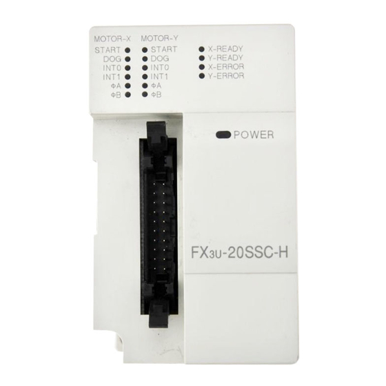
1 Introduction -20SSC-H Positioning Block User's Manual 1.2 External Dimensions and Part Names External Dimensions and Part Names 2 - 4.5 Mounting hole MOTOR-Y START X-READY Y-READY INT0 INT0 X-ERROR INT1 INT1 Y-ERROR POWER 4(0.16") 55(2.17") 87(3.43") [10] Unit: mm (inches) MASS(Weight): 0.3kg (0.66 lbs) Accessory:... -
Page 22: Power And Status Led
1 Introduction -20SSC-H Positioning Block User's Manual 1.3 Power and Status LED Power and Status LED LED display Color Status Description Power is not being supplied from the external power supply or the PLC POWER Green Power is being supplied from the external power supply or the PLC Error is occurring or positioning is being executed on the X/Y axis X-READY Green... -
Page 23: System Configuration
2 System Configuration -20SSC-H Positioning Block User's Manual 2.1 General Configuration System Configuration General Configuration GX Developer FX Configurator-FP (PC) 20SSC-H Monitor data Control data SSCNET III cable Positioning parameter Emergency stop input signal Servo amplifier Servo parameter Upper limit signal USB cable Ladder (MR-J3-B) -
Page 24: Connection With Plc
2 System Configuration -20SSC-H Positioning Block User's Manual 2.2 Connection with PLC Connection with PLC 20SSC-H connects with PLC via extension cable. The 20SSC-H is handled as a special extension block of the PLC. The unit number of the 20SSC-H is automatically assigned No.0 to No.7 starting from the special function unit/block closest to the PLC main unit. -
Page 25: Specifications
3 Specifications -20SSC-H Positioning Block User's Manual 3.1 General Specifications Specifications DESIGN PRECAUTIONS • Provide a safety circuit on the outside of the PLC so that the whole system operates to ensure the safety even when external power supply trouble or PLC failure occurs. Otherwise, malfunctions or output failures may result in an accident. -
Page 26: Power Supply Specification
3 Specifications -20SSC-H Positioning Block User's Manual 3.2 Power Supply Specification Power Supply Specification Item Specification Power supply voltage 24V DC +20% -15% Ripple (p-p) within 5% Permitted instantaneous Operation continues when the instantaneous power failure is shorter than 5ms. External power power failure time supply... -
Page 27: Input Specifications
3 Specifications -20SSC-H Positioning Block User's Manual 3.4 Input Specifications Input Specifications 3.4.1 Input specifications Item Specification X axis interrupt input: X-INT0, X-INT1 Used for interrupt operation Y axis interrupt input: Y-INT0, Y-INT1 Used for interrupt operation X axis near-point DOG input: X-DOG Group 1 Used for zero return Y axis near-point DOG input: Y-DOG... -
Page 28: Pin Configuration
3 Specifications -20SSC-H Positioning Block User's Manual 3.5 Pin Configuration Pin Configuration 3.5.1 Input connector Terminal Terminal Connector pin array (aperture side) Description Description name name X-INT0 Interrupt input (for X axis) Y-INT0 Interrupt input (for Y axis) Not used Not used Y-INT0 X-INT0... -
Page 29: Installation
4 Installation -20SSC-H Positioning Block User's Manual Installation INSTALLATION PRECAUTIONS • Make sure to cut off all phases of the power supply externally before starting the installation or wiring work. Failure to do so may cause electric shock. INSTALLATION PRECAUTIONS •... -
Page 30: Din Rail Mounting
4 Installation -20SSC-H Positioning Block User's Manual 4.1 DIN rail Mounting DIN rail Mounting The product can be mounted on a 35mm wide DIN46277 ( DIN rail. Fit the upper edge (A in the figure to the right) of the DIN rail mounting groove onto the DIN rail. -
Page 31: Wiring
5 Wiring -20SSC-H Positioning Block User's Manual Wiring DESIGN PRECAUTIONS • Observe the following items. Failure to do so may cause incorrect data-writing by noise to PLCs and result the PLC failure, machine damage or an accident. 1) Do not lay close or bundle with the main circuit line, high-voltage line, or load line. Noise and Surge induction interfere with the system operation. -
Page 32: Cable To Be Used, Applicable Connector And Wire Size
5 Wiring -20SSC-H Positioning Block User's Manual 5.1 Cable to Be Used, Applicable Connector and Wire Size WIRING PRECAUTIONS • If the adhesion of solvent and oil to the code part of SSCNET III cable may lower the optical characteristic and machine characteristic. If it is used such an environment, be sure to do the protection measures to the optical cord. -
Page 33: Input Cable And Terminal Block
150 : 1.5m, 300 : 3m, 500 : 5m 3) Applicable connector for user cable (by Mitsubishi Electric) The users should prepare the electric wires and pressure crimp tool. Model name and configuration of I/O connector... -
Page 34: Power Supply Wiring
5 Wiring -20SSC-H Positioning Block User's Manual 5.2 Power Supply Wiring Power Supply Wiring 5.2.1 Power supply wiring 20SSC-H DC24V Class D grounding 5.2.2 Grounding Ground the cables as follows • The grounding resistance should be 100Ω or less. • Grounding should perform independent grounding as far as possible. Independent grounding should be performed for best results. -
Page 35: Input Wiring
5 Wiring -20SSC-H Positioning Block User's Manual 5.3 Input Wiring Input Wiring An external power supply (24VDC) is necessary for the START, DOG, INT0 , INT1 and S/S terminals. 5.3.1 Sink input wiring 20SSC-H DC24V -INT1 Switch (sink type) -INT0 -START -DOG - A+... -
Page 36: Connecting The Sscnet Iii Cable
5 Wiring -20SSC-H Positioning Block User's Manual 5.4 Connecting the SSCNET III Cable Connecting the SSCNET III Cable 5.4.1 Cautions for installation the SSCNET III cable SSCNET III cable is made from optical fiber. If a force is applied to the optical fiber such as a major shock, lateral pressure, haul, sudden bending or twist, its inside distorts or breaks, and optical transmission will not be available. -
Page 37: Cautions For Sscnet Iii Cable Wiring
5 Wiring -20SSC-H Positioning Block User's Manual 5.4 Connecting the SSCNET III Cable 5.4.2 Cautions for SSCNET III cable wiring Secure the cable at close to the connector with bundle material in order to prevent the SSCNET III cable from applying its own weight to the connector. -
Page 38: Memory Configuration And Data Operation
• Do not disassemble or modify the PLC. Doing so may cause failures, malfunctions or fire. * For repair, contact your local Mitsubishi Electric distributor. • Before connecting or disconnecting any extension cable, turn off power. Failure to do so may cause unit failure or malfunctions. -
Page 39: Memory Configuration And Role
6 Memory Configuration and Data Operation -20SSC-H Positioning Block User's Manual 6.1 Memory Configuration and Role Memory Configuration and Role 6.1.1 Memory configuration Store parameters and data necessary for control in the buffer memory (BFM) and flash memory inside 20SSC-H, using the sequence program or FX Configurator-FP. FX Configrator-FP Setting/monitoring tool -20SSC-H Buffer memory (BFM) -
Page 40: Data Type And Role
6 Memory Configuration and Data Operation -20SSC-H Positioning Block User's Manual 6.2 Parameter setting method 6.1.2 Data type and role BFM number Data type Application X-axis Y-axis X-/Y-axis Data indicating the control state. The monitor data is stored in the buffer memory. Monitor the data Monitor data when necessary. -
Page 41: Data Transfer Process
6 Memory Configuration and Data Operation -20SSC-H Positioning Block User's Manual 6.3 Data Transfer Process Data Transfer Process 6.3.1 PLC, 20SSC-H and servo amplifier The data transfer between PLC, 20SSC-H, and servo amplifier is as follows. -20SSC-H Buffer memory (BFM) - Positioning parameter - Servo parameter - Table information... -
Page 42: Fx Configurator-Fp And 20Ssc-H
6 Memory Configuration and Data Operation -20SSC-H Positioning Block User's Manual 6.3 Data Transfer Process 6.3.2 FX Configurator-FP and 20SSC-H The data transfer between FX Configurator-FP and 20SSC-H via the PLC is as follows. FX Configurator-FP Setting/monitoring tool -20SSC-H Buffer memory (BFM) - Positioning parameter - Servo parameter - Table information... -
Page 43: Transfer (Writing) Servo Parameter To Servo Amplifier
6 Memory Configuration and Data Operation -20SSC-H Positioning Block User's Manual 6.3 Data Transfer Process 6.3.3 Transfer (writing) servo parameter to servo amplifier At power-ON, servo parameters in the flash memory are transferred to the servo amplifier. -20SSC-H Buffer memory (BFM) - Positioning parameter - Servo parameter - Table information... -
Page 44: Before Starting Positioning Operation
7 Before Starting Positioning Operation -20SSC-H Positioning Block User's Manual 7.1 Note on Setting Parameters Before Starting Positioning Operation DESIGN PRECAUTIONS • Provide a safety circuit on the outside of the PLC so that the whole system operates to ensure the safety even when external power supply trouble or PLC failure occurs. -
Page 45: Outline Of Positioning Operation
7 Before Starting Positioning Operation -20SSC-H Positioning Block User's Manual 7.2 Outline of Positioning Operation Outline of Positioning Operation The relationship between the operation speed, acceleration/deceleration and travel distance of the positioning operation is shown below. For futher details on the positioning operations suppurted by 20SSC-H and a note on positioning cautions, refer to the following. - Page 46 7 Before Starting Positioning Operation -20SSC-H Positioning Block User's Manual 7.2 Outline of Positioning Operation Note • Trapezoidal acceleration/deceleration and approximate S-shaped acceleration/deceleration If trapezoidal acceleration/deceleration and approximate S-shaped acceleration/deceleration are performed under the same conditions (travel distance, operation speed and acceleration/deceleration time), the positioning time of approximate S-shaped acceleration/deceleration becomes longer by 64ms.
-
Page 47: Handling The Forward Rotation Limit And Reverse Rotation Limit
7 Before Starting Positioning Operation -20SSC-H Positioning Block User's Manual 7.3 Handling the Forward Rotation Limit and Reverse Rotation Limit Handling the Forward Rotation Limit and Reverse Rotation Limit The concept of the forward rotation limit and that of the reverse rotation limit are described. Suppose that limit switches are located as shown in the figure below. -
Page 48: Forward Rotation Limit 2 (Fls) And Reverse Rotation Limit 2 (Rls) [Servo Amplifier Side]
7 Before Starting Positioning Operation -20SSC-H Positioning Block User's Manual 7.3 Handling the Forward Rotation Limit and Reverse Rotation Limit 7.3.1 Forward rotation limit 2 (FLS) and reverse rotation limit 2 (RLS) [servo amplifier side] Connect forward rotation limit 2 (FLS) and reverse rotation limit 2 (RLS) to the upper limit (FLS) and lower limit (RLS) external signal terminals of the servo amplifier, respectively. -
Page 49: Software Limit
7 Before Starting Positioning Operation -20SSC-H Positioning Block User's Manual 7.3 Handling the Forward Rotation Limit and Reverse Rotation Limit 7.3.3 Software limit This operation limit is based on the 0 address that becomes valid after mechanical zero return. Specify at addresses so that activation is before forward rotation limit 1 and reverse rotation limit 1 connected with the PLC. -
Page 50: Handling The Stop Command
7 Before Starting Positioning Operation -20SSC-H Positioning Block User's Manual 7.4 Handling the STOP command Handling the STOP command When the STOP command of 20SSC-H turns ON during positioning operation, the servomotor decelerates to stop. When stopped by the STOP command, the following statuses are shown below. →... - Page 51 7 Before Starting Positioning Operation -20SSC-H Positioning Block User's Manual 7.4 Handling the STOP command 2) Remaining travel distance operation mode When the STOP command is turned ON, operation decelerates to a stop and the 20SSC-H enters standby state for the remaining travel distance operation. At this time, "standby for remaining travel distance"...
-
Page 52: Changing During Operation (Operation Speed, Target Address)
7 Before Starting Positioning Operation -20SSC-H Positioning Block User's Manual 7.5 Changing During Operation (Operation Speed, Target Address) Changing During Operation (Operation Speed, Target Address) 7.5.1 Changing the operation speed with override function This function is possible to change the operation speed at an arbitrary timing through the override setting value (0.1 to 3000.0%). -
Page 53: Changing The Operation Speed With The Operation Speed Change Function
7 Before Starting Positioning Operation -20SSC-H Positioning Block User's Manual 7.5 Changing During Operation (Operation Speed, Target Address) 7.5.2 Changing the operation speed with the operation speed change function This function is possible to change to the specified new operation speed at an arbitrary timing. However, the speed does not change during mechanical zero return after detection of the near point DOG and start of deceleration to the creep speed. -
Page 54: Changing The Target Address
7 Before Starting Positioning Operation -20SSC-H Positioning Block User's Manual 7.5 Changing During Operation (Operation Speed, Target Address) 7.5.3 Changing the target address This function is used to change the target address in positioning control to a new specified address. 1. -
Page 55: Other Functions
7 Before Starting Positioning Operation -20SSC-H Positioning Block User's Manual 7.6 Other functions 4. Cautions • The operation speed can not change in the following statuses. - During deceleration by STOP command - During automatic deceleration in position control • If the target position change value (address) converted in units of pulses is out of the setting range, an error occurs. -
Page 56: Torque Limit Function
7 Before Starting Positioning Operation -20SSC-H Positioning Block User's Manual 7.6 Other functions 2. Applicable positioning operations • Operations applicable to the servo end check • Operations inapplicable to the servo end check - JOG operation - During continuous multi-speed operation - 1-speed positioning operation - During continuous pass operation of - Interrupt 1-speed constant quantity feed... -
Page 57: Absolute Position Detection System
7 Before Starting Positioning Operation -20SSC-H Positioning Block User's Manual 7.6 Other functions 2. Details of control The operation with the torque limit is as follows. Various operations START command *1 , *2 Torque limit setting *1 , *2 Torque output setting Stored torque limit *1 : The torque limit setting or torque output setting becomes valid at the rising edge of the START... -
Page 58: Servo On/Off
7 Before Starting Positioning Operation -20SSC-H Positioning Block User's Manual 7.6 Other functions 3. Absolute position lost If the absolute position in the encoder becomes indefinite in the absolute position detection system, the absolute position loss signal (ABSV) turns ON. At ABSV signal ON, make sure to operate zero return immediately to establish the zero-point again. -
Page 59: Simultaneous Start Function
7 Before Starting Positioning Operation -20SSC-H Positioning Block User's Manual 7.6 Other functions 7.6.7 Simultaneous start function Operation in the X- and Y-axes start simultaneously with this function. → For related parameters, control data and monitor data, refer to Section 7.9 Applicable positioning operations •... -
Page 60: Zero Return Interlock Setting
7 Before Starting Positioning Operation -20SSC-H Positioning Block User's Manual 7.7 Precautions for using the user units (mechanical or composite 7.6.9 Zero return interlock setting This function disables the start command before mechanical return. → For related parameters, control data and monitor data, refer to Section 7.9 1. - Page 61 7 Before Starting Positioning Operation -20SSC-H Positioning Block User's Manual 7.7 Precautions for using the user units (mechanical or composite 2. Converted pulse data Enter data within the setting range of converted pulse data, when setting ranges overlap. The equation for conversion is as follows.
-
Page 62: Cautions For Positioning Operation
7 Before Starting Positioning Operation -20SSC-H Positioning Block User's Manual 7.8 Cautions for Positioning Operation Cautions for Positioning Operation 7.8.1 Overlapped specification of operation mode The positioning operation does not start at START input/command if multiple operation patterns are selected (with multiple bits turned on) in the parameters for operating patterns. - Page 63 7 Before Starting Positioning Operation -20SSC-H Positioning Block User's Manual 7.8 Cautions for Positioning Operation 3. 2-speed positioning operation 1) If the travel distance at the first speed is small If the travel time is smaller than the time needed to decelerate to the operation speed 2, the first operation speed does not reach the operation speed 1.
-
Page 64: Related Parameter, Control Data And Monitor Data
7 Before Starting Positioning Operation -20SSC-H Positioning Block User's Manual 7.9 Related parameter, control data and monitor data Related parameter, control data and monitor data BFM number Item Description X-axis Y-axis Operation parameter ON: Operation for remaining distance Operation STOP mode BFM #14000 b15 BFM #14200 b15 OFF: End of positioning control (initial... - Page 65 7 Before Starting Positioning Operation -20SSC-H Positioning Block User's Manual 7.9 Related parameter, control data and monitor data BFM number Item Description X-axis Y-axis Control data Execute zero return in the zero return Mechanical zero return BFM #518 b6 BFM #618 b6 mode specified with a positioning command parameter.
- Page 66 7 Before Starting Positioning Operation -20SSC-H Positioning Block User's Manual 7.9 Related parameter, control data and monitor data BFM number Item Description X-axis Y-axis Servo parameter Specify the absolute position detection Absolute position detection system. BFM #15003 BFM #15203 system 1:Valid Basic setting 0:Invalid (Default setting)
-
Page 67: Manual Control
8 Manual Control -20SSC-H Positioning Block User's Manual 8.1 Mechanical Zero Return Control Manual Control Mechanical Zero Return Control 8.1.1 Outline of mechanical zero return control The mechanical zero return method for the 20SSC-H includes the following three variations (four modes). →... -
Page 68: Dog Type Zero Return
8 Manual Control -20SSC-H Positioning Block User's Manual 8.1 Mechanical Zero Return Control 8.1.2 DOG type zero return With the DOG type mechanical zero return, the 20SSC-H sets the zero-point, the position as where the module stops with a near-point DOG signal and servo motor zero-point signal. Use the DOG search function to execute the DOG type mechanical zero return arbitrarily. - Page 69 8 Manual Control -20SSC-H Positioning Block User's Manual 8.1 Mechanical Zero Return Control 2. Setting items With DOG type mechanical zero return, specify the following settings. → For details on the setting items, refer to Subsection 8.1.5 Setting item Description Zero return mode Specify the DOG type zero return mode.
-
Page 70: Data-Set Type Mechanical Zero Return
8 Manual Control -20SSC-H Positioning Block User's Manual 8.1 Mechanical Zero Return Control 4) When the limit switch (forward or reverse rotation limit) in the zero return direction turns ON a) The operation is conducted in the direction opposite to the zero return direction at the zero return speed (high speed). -
Page 71: Stopper Type Mechanical Zero Return
8 Manual Control -20SSC-H Positioning Block User's Manual 8.1 Mechanical Zero Return Control 8.1.4 Stopper type mechanical zero return The stopper position is defined as the zero-point. The stopper type mechanical zero return includes the following two types (modes). • Stopper type (1) This mechanical zero return method uses the DOG signal and stopper. - Page 72 8 Manual Control -20SSC-H Positioning Block User's Manual 8.1 Mechanical Zero Return Control 2. Stopper type (2) Acceleration time Speed Maximum speed Zero return speed (creep) Time Stopped due to torque limit Zero return torque limit Mechanical zero return command Positioning completion Zero return completion Current address (user)
-
Page 73: Related Parameters, Control Data And Monitor Data
8 Manual Control -20SSC-H Positioning Block User's Manual 8.1 Mechanical Zero Return Control 8.1.5 Related parameters, control data and monitor data BFM number Item Description X-axis Y-axis Positioning parameter OFF: The current value decreasing direction Zero return direction BFM #14000 b10 BFM #14200 b10 ON: The current value increasing direction OFF: The NO contact for the DOG input logic of... - Page 74 8 Manual Control -20SSC-H Positioning Block User's Manual 8.1 Mechanical Zero Return Control BFM number Item Description X-axis Y-axis Control data Specify the ratio (percent) of the actual operation speed to the operation speed. Override setting BFM #508 BFM #608 ×...
-
Page 75: Jog Operation
8 Manual Control -20SSC-H Positioning Block User's Manual 8.2 JOG Operation JOG Operation 8.2.1 Outline of JOG operation 1. JOG operation Forward pulses are output in the forward JOG mode, while reverse pulses are output in the reverse JOG mode. Deceleration time Acceleration time Maximum speed... - Page 76 8 Manual Control -20SSC-H Positioning Block User's Manual 8.2 JOG Operation 2. Related parameters, control data and monitor data BFM number Item Description X-axis Y-axis Positioning parameter Maximum speed BFM #14009,#14008 BFM #14209,#14208 Setting range: 1 to 2,147,483,647(user unit) JOG speed BFM #14013,#14012 BFM #14213,#14212 Setting range: 1 to 2,147,483,647(user unit)
-
Page 77: Changing The Speed During Jog Operation
8 Manual Control -20SSC-H Positioning Block User's Manual 8.2 JOG Operation 8.2.2 Changing the speed during JOG operation 1. Changing the JOG speed If the in-operation speed change disable turns ON, the JOG speed change is rejected. Speed 10000Hz 7000Hz Time JOG input 10000Hz... -
Page 78: Manual Pulse Generator Operation
8 Manual Control -20SSC-H Positioning Block User's Manual 8.3 Manual pulse generator operation Manual pulse generator operation 8.3.1 Outline of manual pulse generator operation 1. Operation When selecting the MPG (manual pules generator operation) in the operation patterns, the 20SSC-H operates by the MPG input at the START commnand ON. -
Page 79: Current Manual Pulse Input Value
8 Manual Control -20SSC-H Positioning Block User's Manual 8.3 Manual pulse generator operation • The operation speed is proportional to the frequency of pulse strings from the manual pulse generator according to the manual pulse input magnification. In addition, the override setting is invalid. Servo amplifier Manual pulse generator Motor... -
Page 80: Related Parameters, Control Data And Monitor Data
8 Manual Control -20SSC-H Positioning Block User's Manual 8.3 Manual pulse generator operation 8.3.4 Related parameters, control data and monitor data BFM number Item Description X-axis Y-axis Positioning parameter Maximum speed BFM #14009,#14008 BFM #14209,#14208 Setting range:1 to 2,147,483,647(user units) OFF: The FLS/RLS signal of the servo amplifier is FLS/RLS signal not used. -
Page 81: Positioning Control
9 Positioning Control -20SSC-H Positioning Block User's Manual 9.1 Functions Available with Each Positioning Operation Positioning Control This chapter describes the control of each positioning operation. For table operation control, refer to the following section. → For details on table operation, refer to Chapter 10 Functions Available with Each Positioning Operation Reference Approximate S-shaped acceleration/deceleration,... -
Page 82: 1-Speed Positioning Operation
9 Positioning Control -20SSC-H Positioning Block User's Manual 9.2 1-speed Positioning Operation 1-speed Positioning Operation → For details on the operation speed change and target address change, refer to Section 7.5 → For details on torque limit, refer to Subsection 7.6.3 →... -
Page 83: Interrupt 1-Speed Constant Quantity Feed
9 Positioning Control -20SSC-H Positioning Block User's Manual 9.3 Interrupt 1-speed Constant Quantity Feed Interrupt 1-speed Constant Quantity Feed → For details on the operation speed change and target address change, refer to Section 7.5 → For details on torque limit, refer to Subsection 7.6.3 →... -
Page 84: 2-Speed Positioning Operation
9 Positioning Control -20SSC-H Positioning Block User's Manual 9.4 2-speed Positioning Operation 2-speed Positioning Operation → For details on the operation speed change and target address change, refer to Section 7.5 → For details on torque limit, refer to Subsection 7.6.3 →... - Page 85 9 Positioning Control -20SSC-H Positioning Block User's Manual 9.4 2-speed Positioning Operation Note If the moving directions of target address 1 and target address 2 are not the same as follows, a reverse operation is performed immediately after the deceleration stop at target address 1. With the specified absolute address: when the sign difference between the current value and target address 1 is different from the sign difference between target address 1 and target address 2.
-
Page 86: Interrupt 2-Speed Constant Quantity Feed
9 Positioning Control -20SSC-H Positioning Block User's Manual 9.5 Interrupt 2-speed Constant Quantity Feed Interrupt 2-speed Constant Quantity Feed → For details on the operation speed change and target address change, refer to Section 7.5 → For details on torque limit, refer to Subsection 7.6.3 →... -
Page 87: Interrupt Stop Operation
9 Positioning Control -20SSC-H Positioning Block User's Manual 9.6 Interrupt Stop Operation 4. Rotation Direction The sign of the target address decides the operation direction. +: Operates in the direction that increases the current value. (When the value is 0, it is regarded as 1.) Operates in the direction that decreases the current value. -
Page 88: Variable Speed Operation
9 Positioning Control -20SSC-H Positioning Block User's Manual 9.7 Variable Speed Operation Variable Speed Operation → For details on the operation speed change, refer to Section 7.5 → For details on torque limit, refer to Subsection 7.6.3 → For details on STOP command, refer to Section 7.4 →... -
Page 89: Multi-Speed Operation
9 Positioning Control -20SSC-H Positioning Block User's Manual 9.8 Multi-Speed Operation Multi-Speed Operation The multi-speed operation is positioning procedure, available only in the table operation. For the details to control by table operation, and to change the operation speed, refer to the following section. →... - Page 90 9 Positioning Control -20SSC-H Positioning Block User's Manual 9.8 Multi-Speed Operation 4. Position (address) information Absolute address and relative address can be specified in the operation information. With the specified absolute address: Specifies a target address (position) using address 0 as the base. With the specified relative address: Specifies a travel amount from the current address.
-
Page 91: Liner Interpolation Operation
9 Positioning Control -20SSC-H Positioning Block User's Manual 9.9 Liner Interpolation Operation Liner Interpolation Operation → For details on the operation speed change, refer to Section 7.5 → For details on torque limit, refer to Subsection 7.6.3 → For details on STOP command, refer to Section 7.4 →... -
Page 92: Linear Interpolation Operation (Interrupt Stop)
9 Positioning Control -20SSC-H Positioning Block User's Manual 9.10 Linear Interpolation Operation (Interrupt Stop) 9.10 Linear Interpolation Operation (Interrupt Stop) → For details on the operation speed change, refer to Section 7.5 → For details on torque limit, refer to Subsection 7.6.3 →... -
Page 93: Circular Interpolation Operation
9 Positioning Control -20SSC-H Positioning Block User's Manual 9.11 Circular Interpolation Operation 9.11 Circular Interpolation Operation The circular interpolation operation is a positioning procedure, available only in the table operation. The circular interpolation operation has the center coordinate specification/radius specification format. For details on controlling by table operation, and changing the operation speed, refer to the following section. -
Page 94: Circular Interpolation [Radius Specification]
9 Positioning Control -20SSC-H Positioning Block User's Manual 9.11 Circular Interpolation Operation 3. Speed information Actual operation speed (vector speed) is "X-axis operation speed 1 x X-axis override setting." Operation speed 1 of X-axis can be changed using the operation speed change function except for operating under the following conditions. -
Page 95: Parameter, Control Data, Monitor Data And Table Information
9 Positioning Control -20SSC-H Positioning Block User's Manual 9.12 Parameter, Control Data, Monitor Data and Table 2. Operation information Set a circular interpolation operation ("radius, CW direction" or "radius, CCW direction") and an absolute/ relative address in the operation information. →... - Page 96 9 Positioning Control -20SSC-H Positioning Block User's Manual 9.12 Parameter, Control Data, Monitor Data and Table BFM Number Item Description X-axis Y-axis Control data Select motion patterns. b0 : 1-speed positioning operation b1 : Interrupt 1-speed constant quantity feed b2 : 2-speed positioning operation b3 : Interrupt 2-speed constant quantity feed Operation pattern selection...
-
Page 97: Outline Of Table Operation
10 Table Operation -20SSC-H Positioning Block User's Manual 10.1 Outline of Table Operation 10. Table Operation 10.1 Outline of Table Operation This section describes the table information setting and table operation motions. For details on positioning in table operation, refer to the following. →... -
Page 98: Table Information Setting Items
10 Table Operation -20SSC-H Positioning Block User's Manual 10.1 Outline of Table Operation 10.1.3 Table information setting items Type of table information Setting item Content axis axis axis Sets a positioning operation in table operation along with a current address change, etc. No processing Circular interpolation m code... - Page 99 10 Table Operation -20SSC-H Positioning Block User's Manual 10.1 Outline of Table Operation Position Speed Circle informatio Setting m code information information Type Symbol value information fx/f X-axis SINT_X " " " Interrupt 1-speed constant quantity Y-axis SINT_Y " " "...
-
Page 100: Table Operation Execution Procedure
10 Table Operation -20SSC-H Positioning Block User's Manual 10.1 Outline of Table Operation 10.1.4 Table operation execution procedure The following shows the procedure for executing table operation and describes the operation. Set the operation pattern of the control data and the table start No. BFM number Item Content... -
Page 101: How To Set Table Information
10 Table Operation -20SSC-H Positioning Block User's Manual 10.2 How to Set Table Information 10.2 How to Set Table Information 20SSC-H has 2 procedures to set table information, via FX Configurator-FP or by a sequence program. Setting table information by sequence program To set table information by sequence program, write each setting to 20SSC-H buffer memory by TO instruction, or move instructions (MOV, etc.) for direct specification. - Page 102 10 Table Operation -20SSC-H Positioning Block User's Manual 10.2 How to Set Table Information The position of the operation information is different. a) Position information d) m code information b) Speed information e) Circle information c) Operation information 1) X-axis, Y-axis table information Buffer memory m code Position...
- Page 103 10 Table Operation -20SSC-H Positioning Block User's Manual 10.2 How to Set Table Information 2) XY-axis table information Buffer memory Position information Speed infornation Circle infornation Operation m code information Table No. information X-axis Y-axis X-axis Y-axis X-axis Y-axis 5000 5000 5000 5000...
-
Page 104: Tables And Bfm No. Allocation
10 Table Operation -20SSC-H Positioning Block User's Manual 10.3 Tables and BFM No. Allocation 10.3 Tables and BFM No. Allocation Stores the table operation information to the 20SSC-H buffer memory. There are 2 BFM types, one for operation by individual axis (X/Y axis) and the other for XY-axis simultaneous operation. BFM No. -
Page 105: Current Position Change
10 Table Operation -20SSC-H Positioning Block User's Manual 10.4 Current Position Change 10.4 Current Position Change This operation information changes the current address (user/pulse) value to the one specified in the position (address) information. 10.5 Absolute Address Specification This operation information sets the position data of subsequent table operations to an absolute address based on the (0, 0) point. -
Page 106: M Code
10 Table Operation -20SSC-H Positioning Block User's Manual 10.9 m code 10.9 m code The m code is an auxiliary command to support positioning data in execution. When an m code turns ON in table operation, 20SSC-H stores the table No. in monitor data as an m code number, while also turning ON the m code ON flag in status information. -
Page 107: 10.9.2 With Mode
10 Table Operation -20SSC-H Positioning Block User's Manual 10.9 m code 10.9.2 With mode The specified m code turns ON when the operation starts. → For details on related setting items, refer to Subsection 10.9.3 1. Operation Speed Time 10010 10011 m code No. -
Page 108: 10.9.3 Related Buffer Memory
10 Table Operation -20SSC-H Positioning Block User's Manual 10.9 m code 10.9.3 Related buffer memory BFM number Item Content X-axis Y-axis Control data Operation m code OFF When this command is ON, the m code is turned BFM #518 b11 BFM #618 b11 command 1 command... -
Page 109: 10.10 Continuous Pass Operation
10 Table Operation -20SSC-H Positioning Block User's Manual 10.10 Continuous Pass Operation 10.10 Continuous Pass Operation Continuously executing interpolation operation (linear interpolation, circular interpolation) results in a continuous pass operation. 1. Operations valid for continuous pass operation • Operations that result in continuous pass •... -
Page 110: Buffer Memory (Parameters & Monitored Data)
11 Buffer Memory (Parameters & Monitored Data) -20SSC-H Positioning Block User's Manual 11.1 Positioning Parameters 11. Buffer Memory (Parameters & Monitored Data) 11.1 Positioning Parameters The positioning parameters to set speed and units of measurement. The BFMs in positioning parameters are readable/writable. For X-axis: BFM #14000 to #14199 For Y-axis: BFM #14200 to #14399 Caution... - Page 111 11 Buffer Memory (Parameters & Monitored Data) -20SSC-H Positioning Block User's Manual 11.1 Positioning Parameters BFM Number Description Default Number X-axis Y-axis STOP mode 1: Suspends the operation, and the START command starts the operation for the remaining travel distance. H0000 #14000 #14200...
-
Page 112: Operation Parameters 2 [Bfm #14002, Bfm #14202]
11 Buffer Memory (Parameters & Monitored Data) -20SSC-H Positioning Block User's Manual 11.1 Positioning Parameters 11.1.2 Operation parameters 2 [BFM #14002, BFM #14202] BFM Number Description Default Number X-axis Y-axis Enables or disables the servo end check function. →For details on the servo end check, refer to Subsection 7.5.2. 1: Enable At an in-position signal, determinates the positioning operation completion 0: Disable... -
Page 113: Maximum Speed [Bfm #14009, #14008, Bfm #14209, #14208]
11 Buffer Memory (Parameters & Monitored Data) -20SSC-H Positioning Block User's Manual 11.1 Positioning Parameters 11.1.5 Maximum speed [BFM #14009, #14008, BFM #14209, #14208] This parameter sets the maximum speed for each operation. → For details on the maximum speed, refer to Section 7.2 BFM Number Description Default... -
Page 114: Acceleration Time [Bfm #14018, Bfm #14218]
11 Buffer Memory (Parameters & Monitored Data) -20SSC-H Positioning Block User's Manual 11.1 Positioning Parameters 11.1.8 Acceleration time [BFM #14018, BFM #14218] This parameter sets a time for the operation speed to reach the maximum speed from zero. → For details on the acceleration time, refer to Section 7.2 BFM Number Description Default... -
Page 115: Zero Return Speed (Creep) [Bfm #14027, #14026, Bfm #14227, #14226]
11 Buffer Memory (Parameters & Monitored Data) -20SSC-H Positioning Block User's Manual 11.1 Positioning Parameters 11.1.12 Zero return speed (Creep) [BFM #14027, #14026, BFM #14227, #14226] This parameter sets the mechanical zero return operation speed (creep) [DOG, Stopper #1, #2]. →... -
Page 116: Zero Return Mode [Bfm #14031, Bfm #14231]
11 Buffer Memory (Parameters & Monitored Data) -20SSC-H Positioning Block User's Manual 11.1 Positioning Parameters 11.1.15 Zero return mode [BFM #14031, BFM #14231] This parameter selects mechanical zero return operations. → For details on the zero return operation, refer to Section 8.1 BFM Number Description Default... -
Page 117: Torque Limit [Bfm #14038, Bfm #14238]
11 Buffer Memory (Parameters & Monitored Data) -20SSC-H Positioning Block User's Manual 11.1 Positioning Parameters 11.1.18 Torque limit [BFM #14038, BFM #14238] This parameter sets the torque limit for the servo motor and magnifies the servo motor torque in the range from 0.1 to 1000.0%. -
Page 118: Servo Parameters
11 Buffer Memory (Parameters & Monitored Data) -20SSC-H Positioning Block User's Manual 11.2 Servo Parameters 11.2 Servo Parameters Various parameters for the servo amplifier can be set. The following buffer memories in servo parameters are readable and writable. For details on the servo amplifier parameters in the table below with their parameter numbers, refer to the manual of the servo amplifier. -
Page 119: Servo Parameters (Gain/Filter Settings)
11 Buffer Memory (Parameters & Monitored Data) -20SSC-H Positioning Block User's Manual 11.2 Servo Parameters BFM Number Servo Amplifier Name Description Default X-axis Y-axis Parameter No. Set this if you want to improve the servo amplifier response. High responsivity Low responsivity PA09 Auto tuning response 32:(400.0Hz) - Page 120 11 Buffer Memory (Parameters & Monitored Data) -20SSC-H Positioning Block User's Manual 11.2 Servo Parameters BFM Number Servo Amplifier Name Description Default X-axis Y-axis Parameter No. Specify the notch shape used for the machine resonance suppression filter 2 (Notch shape selection 2). Mechanical resonance suppression filter selection Notch depth selection...
-
Page 121: Servo Parameters (Advanced Setting)
11 Buffer Memory (Parameters & Monitored Data) -20SSC-H Positioning Block User's Manual 11.2 Servo Parameters BFM Number Servo Amplifier Name Description Default X-axis Y-axis Parameter No. Gain changing Set the position loop gain when the gain changing is valid. PB30 #15048 #15248 Position loop gain... - Page 122 11 Buffer Memory (Parameters & Monitored Data) -20SSC-H Positioning Block User's Manual 11.2 Servo Parameters BFM Number Servo Amplifier Name Description Default X-axis Y-axis Parameter No. Select a signal to be output to the analog monitor 1. Analog monitor 1(MO1) output selection 0: Servo motor speed (±8V at the maximum) 1: Torque (±8 V at the maximum) 2: Servo motor speed (+8V at the maximum)
-
Page 123: Servo Parameters (I/O Setting)
11 Buffer Memory (Parameters & Monitored Data) -20SSC-H Positioning Block User's Manual 11.2 Servo Parameters 11.2.4 Servo parameters (I/O setting) BFM Number Servo Amplifier Name Description Default X-axis Y-axis Parameter No. Specify a signal assigned (output) to the CN3-13 connector of the servo amplifier. - Page 124 11 Buffer Memory (Parameters & Monitored Data) -20SSC-H Positioning Block User's Manual 11.2 Servo Parameters BFM Number Servo Amplifier Name Description Default X-axis Y-axis Parameter No. Specify a signal assigned (output) to the CN3-15 connector of the servo amplifier. Select CN3-15 pin output device 00: Always OFF 01: RDY (ready ON) 02: RD (servo ON)
-
Page 125: Monitor Data
11 Buffer Memory (Parameters & Monitored Data) -20SSC-H Positioning Block User's Manual 11.3 Monitor Data 11.3 Monitor Data Operating conditions for the positioning system are stored as monitor data. The following buffer memories for monitor data are read-only memories except for the current address (user) [BFM #1, #0 (X-axis), BFM #101, #100 (Y-axis)]. -
Page 126: Torque Limit Storing Value [Bfm #5, #4, Bfm #104, #105]
11 Buffer Memory (Parameters & Monitored Data) -20SSC-H Positioning Block User's Manual 11.3 Monitor Data 11.3.3 Torque limit storing value [BFM #5, #4, BFM #104, #105] Torque limit value used for the torque limit function is stored. The torque limit value is a torque limit setting value, torque output setting value or zero return torque limit value. -
Page 127: Current Value Of Operation Speed [Bfm #11, #10, Bfm #111, #110]
11 Buffer Memory (Parameters & Monitored Data) -20SSC-H Positioning Block User's Manual 11.3 Monitor Data 11.3.8 Current value of operation speed [BFM #11, #10, BFM #111, #110] The current value of operation speed is stored. The value becomes zero under suspension, or in operation with a manual pulse input. BFM Number Description Value Format... -
Page 128: Status Information [Bfm #28, Bfm #128]
11 Buffer Memory (Parameters & Monitored Data) -20SSC-H Positioning Block User's Manual 11.3 Monitor Data 11.3.13 Status information [BFM #28, BFM #128] Status of the 20SSC-H can be checked by ON/OFF statuses of each bit. BFM Number Description Value Format Default Number X-axis... -
Page 129: Error Code [Bfm #29, Bfm #129]
11 Buffer Memory (Parameters & Monitored Data) -20SSC-H Positioning Block User's Manual 11.3 Monitor Data BFM Number Description Value Format Default Number X-axis Y-axis Initialization of buffer memory is in progress. • This bit is ON while initializing data in buffer memories. •... -
Page 130: Model Code [Bfm #30]
11 Buffer Memory (Parameters & Monitored Data) -20SSC-H Positioning Block User's Manual 11.3 Monitor Data 11.3.15 Model code [BFM #30] The model code of the 20SSC-H has been stored. BFM Number Description Value Format Default X-axis Y-axis BFM #30 The model code of the 20SSC-H is K5220. Decimal 11.3.16 Deviation counter value [BFM #51, #50, BFM #151, #150] The deviation counter value of the servo amplifier is stored. -
Page 131: Servo Parameter Error Numbers [Bfm #62, Bfm #162]
11 Buffer Memory (Parameters & Monitored Data) -20SSC-H Positioning Block User's Manual 11.3 Monitor Data 11.3.20 Servo parameter error numbers [BFM #62, BFM #162] Parameter numbers that has caused servo parameter errors are stored. BFM Number Description Value Format Default X-axis Y-axis BFM #62... -
Page 132: Regenerative Load Ratio [Bfm #65, Bfm #165]
11 Buffer Memory (Parameters & Monitored Data) -20SSC-H Positioning Block User's Manual 11.3 Monitor Data 11.3.22 Regenerative load ratio [BFM #65, BFM #165] The regenerative load ratio power to the maximum regenerative power is stored in percentage. With regenerative brake option, the regenerative power ratio of the allowable capacity is stored. BFM Number Description Value Format... -
Page 133: Control Data
11 Buffer Memory (Parameters & Monitored Data) -20SSC-H Positioning Block User's Manual 11.4 Control Data 11.4 Control Data The control data is user-specified data for controlling the positioning system. For X-axis: BFM #500 to #599 For Y-axis: BFM #600 to #699 Caution Do not use unlisted BFMs for changing values not described in this section. -
Page 134: Target Address 2 [Bfm #505, #504, Bfm #605, #604]
11 Buffer Memory (Parameters & Monitored Data) -20SSC-H Positioning Block User's Manual 11.4 Control Data 11.4.3 Target address 2 [BFM #505, #504, BFM #605, #604] This data item sets a target position or travel for positioning operation distance as the target address 2. BFM Number Description Default... -
Page 135: Velocity Change Value [Bfm #513, #512, Bfm #613, #612]
11 Buffer Memory (Parameters & Monitored Data) -20SSC-H Positioning Block User's Manual 11.4 Control Data 11.4.7 Velocity change value [BFM #513, #512, BFM #613, #612] This data item sets the velocity change value. → For details on the operation speed change function, refer to Subsection 7.5.2 BFM Number Description Default... - Page 136 11 Buffer Memory (Parameters & Monitored Data) -20SSC-H Positioning Block User's Manual 11.4 Control Data BFM Number Setting Item Description Default Detection Number X-axis Y-axis When this is set, mechanical zero return operation is started. Mechanical zero →For details on the mechanical zero return, Edge return command refer to Section 8.1...
-
Page 137: Operation Command 2 [Bfm #519, Bfm #619]
11 Buffer Memory (Parameters & Monitored Data) -20SSC-H Positioning Block User's Manual 11.4 Control Data 11.4.11 Operation command 2 [BFM #519, BFM #619] BFM Number Setting Item Description Default Detection Number X-axis Y-axis Set this to cancel the standby status for the remaining travel Remaining travel after the STOP command. -
Page 138: Operation Pattern Selection [Bfm #520, Bfm #620]
11 Buffer Memory (Parameters & Monitored Data) -20SSC-H Positioning Block User's Manual 11.4 Control Data 11.4.12 Operation pattern selection [BFM #520, BFM #620] BFM Number Setting Item Description Default Detection Number X-axis Y-axis 1-speed Set this to perform 1-speed positioning operation. →For details on the 1-speed positioning operation, positioning operation... -
Page 139: Control Command Enable/Disable [Bfm #522]
11 Buffer Memory (Parameters & Monitored Data) -20SSC-H Positioning Block User's Manual 11.4 Control Data 11.4.14 Control command enable/disable [BFM #522] This data item enables or disables control commands. Once the model code is stored, control commands are enabled. BFM Number Description Default X-axis... -
Page 140: Manual Pulse Generator Input Magnification (Numerator) [Bfm #525, #524, Bfm #625, #624]
11 Buffer Memory (Parameters & Monitored Data) -20SSC-H Positioning Block User's Manual 11.4 Control Data Notes on saving data into flash memory • The save command is ignored during a positioning operation. • Be sure to note the following points while saving data into the flash memory (status information: ON). - Do not turn the power OFF while saving data into the flash memory. -
Page 141: Table Information
11 Buffer Memory (Parameters & Monitored Data) -20SSC-H Positioning Block User's Manual 11.5 Table Information 11.5 Table Information This section shows BFMs for positioning in table operation. Table numbers and BFM numbers are assigned as shown in the table below. For details on the table operation, refer to the following. - Page 142 11 Buffer Memory (Parameters & Monitored Data) -20SSC-H Positioning Block User's Manual 11.5 Table Information 1. Position information Set the following items according to the table operations set in the operation information. Table Operation Item Description Action Setting range: -2,147,483,648 to 2,147,483,647 [User unit] Positioning operation Set the target address.
- Page 143 11 Buffer Memory (Parameters & Monitored Data) -20SSC-H Positioning Block User's Manual 11.5 Table Information Position Speed Circular m code informa- Abbrevi- Setting information information Type Meaning informa- tion ation value tion fx/f " " " X-axis DINT_X " Interrupt 2-speed "...
-
Page 144: 12. Program Example
• Do not disassemble or modify the PLC. Doing so may cause failures, malfunctions or fire. For repair, contact your local Mitsubishi Electric distributor. • Before connecting or disconnecting any extension cable, turn off power. Failure to do so may cause unit failure or malfunctions. -
Page 145: Reading/Writing Buffer Memory
12 Program Example -20SSC-H Positioning Block User's Manual 12.1 Reading/Writing Buffer Memory 12.1 Reading/Writing Buffer Memory 12.1.1 Assigned unit number 1. Assigned unit number The unit number for the 20SSC-H is automatically assigned No.0 to No.7 starting from the special function unit/block closest to the PLC main unit. - Page 146 12 Program Example -20SSC-H Positioning Block User's Manual 12.1 Reading/Writing Buffer Memory 2) Example 2 In the following program example, 32-bit data in data registers (D21,D20) is written to buffer memory (BFM #501,#500) in unit No.1. Write command FNC 12 U1\G500 DMOV Transfer...
-
Page 147: Device Assignments
12 Program Example -20SSC-H Positioning Block User's Manual 12.2 Device Assignments 12.2 Device Assignments Device No. Name Remark X-axis Y-axis Input Error reset X000 X010 STOP X001 X011 Forward rotation limit X002 X012 Use external wiring with NC contacts. Reverse rotation limit X003 X013 Forward rotation JOG... -
Page 148: Explanation Of Operation
12 Program Example -20SSC-H Positioning Block User's Manual 12.3 Explanation of Operation Device No. Name Remark X-axis Y-axis Monitor data READY M140 During forward rotation pulse output M141 During reverse rotation pulse output M142 Zero return completed M143 Current value overflow M144 Error occurrence M145... -
Page 149: 12.3.1 Mechanical Zero Return
12 Program Example -20SSC-H Positioning Block User's Manual 12.3 Explanation of Operation 12.3.1 Mechanical zero return Acceleration time Deceleration time (200ms) (200ms) Maximum speed Speed (4,000,000Hz) OPR speed(High-speed) OPR speed 4,000,000Hz (creep) 100,000Hz Time Zero-phase signal X-axis 1) When turning X006 "X-axis mechanical zero return command" to ON at the PLC main unit, DOG type mechanical zero return operation starts in the current value decrementing direction. -
Page 150: 12.3.3 1-Speed Positioning Operation
12 Program Example -20SSC-H Positioning Block User's Manual 12.3 Explanation of Operation 12.3.3 1-speed positioning operation The 1-speed positioning operation operates by the drive for incrementing. The positioning operates at constant quantity feed. Acceleration time Deceleration time (200ms) (200ms) Maximum speed Speed (4,000,000Hz) Operation speed 1... - Page 151 12 Program Example -20SSC-H Positioning Block User's Manual 12.3 Explanation of Operation X-axis • When turnig X007 "X-axis START command" to ON with X022 "X-axis selection of table operation (individual)" turned ON, multi-speed operation preset to X-axis table information starts. After 10,000,000 pulses of travel in the current value incrementing direction, operation decelerates to stop.
-
Page 152: Circular Interpolation Operation [Table Operation (Simultaneous)]
12 Program Example -20SSC-H Positioning Block User's Manual 12.4 Sequence Program 12.3.5 Circular interpolation operation [table operation (simultaneous)] Circular interpolation operation works in table operation. In this example, circular interpolation operation functions by the drive to increment. 1. Operation details Y-axis 2,000,000 1,000,000... - Page 153 12 Program Example -20SSC-H Positioning Block User's Manual 12.4 Sequence Program RUN monitor M8000 FNC 12 X-axis status information U0\G28 K4M40 BFM #28 M40 to M55 FNC 12 Y-axis status information X-axis U0\G128 K4M140 BFM #128 M140 to M155 unit ready Y-axis unit ready M149 Unit...
- Page 154 12 Program Example -20SSC-H Positioning Block User's Manual 12.4 Sequence Program From previous page From previous page Select Y-axis operation pattern. Selection of Y-axis 1-speed positioning operation X021 Y-axis 1-speed M100 positioning operation RUN monitor M8000 Y-axis interrupt 1-speed M101 constant quantity feed Y-axis 2-speed M102...
- Page 155 12 Program Example -20SSC-H Positioning Block User's Manual 12.4 Sequence Program From previous page From previous page Select X-axis operation command. X-axis error reset X000 X-axis error reset X-axis STOP X001 X-axis STOP X-axis forward rotation limit X002 X-axis forward rotation limit X-axis reverse rotation limit X003...
- Page 156 12 Program Example -20SSC-H Positioning Block User's Manual 12.4 Sequence Program From previous page From previous page RUN monitor M8000 Simultaneous start flag (In this example, always OFF) X-axis M code ON FNC232 M31 X-axis m code K10003 AND= OFF command RUN monitor X-axis change command in M8000...
- Page 157 12 Program Example -20SSC-H Positioning Block User's Manual 12.4 Sequence Program From previous page From previous page RUN monitor M8000 M130 Always OFF Y-axis M code ON M148 FNC232 Y-axis m code OFF D109 K11003 M131 AND= command RUN monitor Y-axis change command in M8000 operation disable...
- Page 158 12 Program Example -20SSC-H Positioning Block User's Manual 12.4 Sequence Program From previous page From previous page Read Y-axis monitor data from 20SSC-H. RUN monitor M8000 FNC 12 Y-axis current address (user) U0\G100 D100 DMOV BFM #101,#100 D101,D100 FNC 12 Y-axis error BFM No.
-
Page 159: 13. Diagnostics
• Do not disassemble or modify the PLC. Doing so may cause failures, malfunctions or fire. For repair, contact your local Mitsubishi Electric distributor. • Before connecting or disconnecting any extension cable, turn off power. Failure to do so may cause unit failure or malfunctions. -
Page 160: 13.1.1 Check Leds
For details on error codes, refer to the following: Y-ERROR →Refer to subsection 13.2.3 If the 20SSC-H does not restore the problem at power ON CPU error again, consult a Mitsubishi Electric distributor. 13.1.2 Input LED state indications Color State Content of Error... -
Page 161: Check Error Code
13 Diagnostics -20SSC-H Positioning Block User's Manual 13.2 Check Error Code 13.2 Check Error Code 13.2.1 Checking errors When an error or warning (servo amplifier) occurs, error or warning information is stored to the following buffer memories. FX Configurator-FP and GX-Developer check the error by monitoring, and so does a sequence program. BFM number Item Content... -
Page 162: Error Code List [Bfm #29 (X-Axis), Bfm #129 (Y-Axis)]
13 Diagnostics -20SSC-H Positioning Block User's Manual 13.2 Check Error Code 13.2.3 Error code list [BFM #29 (X-axis), BFM #129 (Y-axis)] When an error occurs an error code is stored in decimal to BFM #29 (X-axis) and BFM #129 (Y-axis). Error Error category Code... - Page 163 Major errors 20SSC-H, the module needs repair. 9002 Watchdog timer error Consult a Mitsubishi Electric distributor. 9003 Hardware error Parentheses ( ) in the error code column indicate the LED display on the servo amplifier. →For details on how to check errors and actions, refer to the manual of the servo amplifier to be connected.
- Page 164 13 Diagnostics -20SSC-H Positioning Block User's Manual 13.2 Check Error Code Error Error category Code Error Content Action (decimal) Parentheses ( ) in the error code column indicate the LED display on the servo amplifier. →For details on how to check errors and actions, refer to the manual of the servo amplifier to be connected. Regenerative alarm •...
- Page 165 13 Diagnostics -20SSC-H Positioning Block User's Manual 13.2 Check Error Code Error Error category Code Error Content Action (decimal) Parentheses ( ) in the error code column indicate the LED display on the servo amplifier. →For details on how to check errors and actions, refer to the manual of the servo amplifier to be connected. Main circuit device overheat •...
-
Page 166: Servo Warning List [Bfm #68 (X-Axis), Bfm #168 (Y-Axis)]
The servo amplifier must be repaired. Consult a (888) • CPU/part fault Mitsubishi Electric distributor. 13.2.4 Servo warning list [BFM #68 (X-axis), BFM #168 (Y-axis)] The warning detected by the servo amplifier is stored. Remove the cause of the warning. - Page 167 If this error occurs after rebooting and initializing the 2147 The watchdog error occurred on the 20SSC-H. 20SSC-H the module needs repair. Consult a Mitsubishi Electric distributor. Cooling fan speed reduction warning • Replace the cooling fan of the servo amplifier.
-
Page 168: Diagnostics On The Plc Main Unit
If the power is not OFF, check the power supply and the power supply occurred: route. • The power supply is OFF. If power is being supplied correctly, consult a Mitsubishi Electric • Incorrect external wiring. distributor. • Power of the specified voltage is not •... -
Page 169: Error Led [On/Flashing/Off]
Fit a noise filter onto the power supply line. 3) If the ERROR LED does not go out even after measures in 1) and 2) are adopted, consult a Mitsubishi Electric distributor. One of the following errors has occurred on... -
Page 170: Appendix A: List Of Parameters And Data
Appendix A: LIST OF PARAMETERS AND DATA -20SSC-H Positioning Block User's Manual Appendix A-1 Monitor Data List Appendix A: LIST OF PARAMETERS AND DATA Appendix A-1 Monitor Data List BFM Number Value of Default Item Description Reference monitor value X axis Y axis BFM #1,#0 Current address (user) - Page 171 Appendix A: LIST OF PARAMETERS AND DATA -20SSC-H Positioning Block User's Manual Appendix A-1 Monitor Data List BFM Number Value of Default Item Description Reference monitor value X axis Y axis Servo parameter error BFM #62 BFM #162 Stores parameter number of servo parameter Hexadecimal subsection 11.3.20 number...
-
Page 172: Appendix A-2 Control Data Table
Appendix A: LIST OF PARAMETERS AND DATA -20SSC-H Positioning Block User's Manual Appendix A-2 Control Data Table Appendix A-2 Control Data Table BFM number Default Item Description/Setting range Reference value X axis Y axis Target address1 subsection 11.4.1 -2,147,483,648 to 2,147,483,647 (user unit) #501,#500 #601,#600 Operation speed1... - Page 173 Appendix A: LIST OF PARAMETERS AND DATA -20SSC-H Positioning Block User's Manual Appendix A-2 Control Data Table BFM number Default Item Description/Setting range Reference value X axis Y axis Stores positioning parameters of X axis (BFM#14000 to BFM #14199) to flash memory Stores positioning parameters of Y axis(BFM#14200 to BFM #14399) to flash memory Stores table information of X axis (BFM #1000 to...
-
Page 174: Appendix A-3 Table Information List
Appendix A: LIST OF PARAMETERS AND DATA -20SSC-H Positioning Block User's Manual Appendix A-3 Table Information List Appendix A-3 Table Information List BFM number Table Default Refe- Item Description/Setting range number value rence X axis Y axis XY axis Positioning: Position data #1001,#1000 #7001,#7000... - Page 175 Appendix A: LIST OF PARAMETERS AND DATA -20SSC-H Positioning Block User's Manual Appendix A-3 Table Information List The operation information includes the following items. -1: No processing (NOP) 19: Linear interpolation (LIN) -1: m code (NOP) 20: Linear interpolation (interrupt stop) (LIN_INT) 0: End (END) 21: Circular interpolation (center, CW direction)(CW_i) 1: 1-speed positioning (DRV_X)
-
Page 176: Appendix A-4 Positioning Parameter List
Appendix A: LIST OF PARAMETERS AND DATA -20SSC-H Positioning Block User's Manual Appendix A-4 Positioning parameter List Appendix A-4 Positioning parameter List BFM number Default Item Description/Setting range Reference value X axis Y axis b1,b0 System of units (user unit) (motor, mechanical, composite system) b3,b2 Unit of measurement for the user units (µm, Ccm/min, 10... - Page 177 Appendix A: LIST OF PARAMETERS AND DATA -20SSC-H Positioning Block User's Manual Appendix A-4 Positioning parameter List BFM number Default Item Description/Setting range Reference value X axis Y axis Use/ not use FLS, RLS signal servo amplifier Use/ not use DOG signal of servo amplifier b7 to b2 Zero return interlock setting enabled/disabled External input selection...
-
Page 178: Appendix A-5 Servo Parameter List
Appendix A: LIST OF PARAMETERS AND DATA -20SSC-H Positioning Block User's Manual Appendix A-5 Servo Parameter List Appendix A-5 Servo Parameter List BFM number Default Item Settings Reference value X axis Y axis Servo amplifier series Setting of servo amplifier series connected to 20SSC-H #15000 #15200 Regeneration option... - Page 179 Appendix A: LIST OF PARAMETERS AND DATA -20SSC-H Positioning Block User's Manual Appendix A-5 Servo Parameter List BFM number Default Item Settings Reference value X axis Y axis Low-pass filter selection Selects setting method (auto/manual) of low-pass filter H0000 #15041 #15241 Slight vibration Selects slight vibration suppression control (validity of the...
- Page 180 Appendix A: LIST OF PARAMETERS AND DATA -20SSC-H Positioning Block User's Manual Appendix A-5 Servo Parameter List MEMO...
-
Page 181: Warranty
Any other failure found not to be the responsibility controller range of applications. of Mitsubishi or that admitted not to be so by the However, in certain cases, some applications may be user. -
Page 182: Revised History
-20SSC-H Positioning Block User's Manual Revised History Revised History Date Revision Discription 12/2005 First Edition... - Page 184 -20SSC-H USER’S MANUAL HEAD OFFICE: TOKYO BUILDING, 2-7-3 MARUNOUCHI, CHIYODA-KU, TOKYO 100-8310, JAPAN HIMEJI WORKS: 840, CHIYODA CHO, HIMEJI, JAPAN FX3U-20SSC-U-E MODEL 09R622 MODEL CODE JY997D21301A Effective Dec. 2005 (MEE) Specifications are subject to change without notice.
Need help?
Do you have a question about the FX3U-20SSC-H and is the answer not in the manual?
Questions and answers