Siemens SITRANS WS300 Operating Instructions Manual
Speed sensors
Hide thumbs
Also See for SITRANS WS300:
- Operating instructions manual (40 pages) ,
- Technical bulletin (5 pages) ,
- Operating instructions manual (32 pages)
Table of Contents
Advertisement
Quick Links
Advertisement
Table of Contents

Related Manuals for Siemens SITRANS WS300


Summary of Contents for Siemens SITRANS WS300
- Page 1 Speed Sensors SITRANS WS300 Operating Instructions 05/2010 SITRANS...
- Page 2 The user is responsible for all changes and repairs made to the device by the user or the user’s agent. • All new components are to be provided by Siemens Milltronics Process Instruments Inc. • Restrict repair to faulty components only.
-
Page 3: Table Of Contents
Table of Contents Safety Notes .............................1 Safety Marking Symbols ......................1 The Manual ...............................2 Technical Support ..........................2 SITRANS WS300 Speed Sensor ..................3 Specifications ........................4 Installation .......................... 6 Dimensions ...............................6 Mounting ..............................7 Mounting to a Tail Pulley ......................8 Mounting to a Bend or Snub Pulley ..................9 Mounting using Optional Threaded Shaft Coupling ............10... -
Page 5: Safety Notes
Safety Marking Symbols In manual: On product: Description WARNING: refer to accompanying documents (manual) for details. This symbol is used when there is no corresponding symbol on the product. 7ML19985ML01 SITRANS WS300 Speed Sensor – OPERATING INSTRUCTIONS Page 1... -
Page 6: The Manual
Please direct your comments to techpubs.smpi@siemens.com. Technical Support Support is available 24 hours a day. To find your local Siemens Automation Office address, phone or fax number go to: www.siemens.com/automation/partner •Click on the tab Contacts by Product and then find your product group (+Process Automation >... -
Page 7: Sitrans Ws300 Speed Sensor
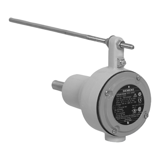
SITRANS WS300 Speed Sensor SITRANS WS300 speed sensor is a low- to high-resolution shaft driven speed sensor. It measures the shaft's rotation by sending pulses to the integrator. The WS300 is certified for use in hazardous and non-hazardous locations. This small, light-weight speed sensor features: •... -
Page 8: Specifications
• IS: 2-wire shielded 0.324 mm (22 AWG) • maximum cable run 305 m (1000 ft) Weight • 1.22 kg (2.68 lbs) aluminum • 2.41 kg (5.3 lbs) stainless steel Page 4 SITRANS WS300 Speed Sensor – OPERATING INSTRUCTIONS 7ML19985ML01... - Page 9 Class I, Div. 1, Groups A, B, C, D Class II, Div. 1, Groups E, F, G Based on the ATEX rating of the NAMUR sensor and CSA/FM system approvals. 7ML19985ML01 SITRANS WS300 Speed Sensor – OPERATING INSTRUCTIONS Page 5...
-
Page 10: Installation
Shaft ø: 15.9 mm (5/8") 102 mm (4.03") ½" NPT conduit entrance (optional M20 adapter available) 159 mm 102 mm (6.25") (4.00") 111 mm (4.36") ½" NPT conduit entrance (optional M20 adapter available) Page 6 SITRANS WS300 Speed Sensor – OPERATING INSTRUCTIONS 7ML19985ML01... -
Page 11: Mounting
For shafts that do not have enough material protruding to use a set screw, or that cannot be removed for modification, a threaded shaft coupling can be used. 7ML19985ML01 SITRANS WS300 Speed Sensor – OPERATING INSTRUCTIONS Page 7... -
Page 12: Mounting To A Tail Pulley
When adjusting the belt take up, ensure there is play on the arrestor rod. If the arrestor rod is pushed against the end of its travel slot, premature wear may result on the bearing. Page 8 SITRANS WS300 Speed Sensor – OPERATING INSTRUCTIONS 7ML19985ML01... -
Page 13: Mounting To A Bend Or Snub Pulley
89 mm 3.5" WS300 flexible conduit pulley bearing When mounting to a bend or snub pulley only a 3/8” (10 mm) drilled hole is Note: required for the arrestor rod. 7ML19985ML01 SITRANS WS300 Speed Sensor – OPERATING INSTRUCTIONS Page 9... -
Page 14: Mounting Using Optional Threaded Shaft Coupling
25 mm M12x1.75 (1.0") .254mm (.010") A M12x1.75 (use adhesive when installing threaded shaft coupling (e.g. Loctite) All other installation instructions apply. See “General Installation Steps” on Note: page 11. Page 10 SITRANS WS300 Speed Sensor – OPERATING INSTRUCTIONS 7ML19985ML01... -
Page 15: General Installation Steps
Attach spring to arresting rod and frame. Encase wiring in flexible conduit to allow unit to float. Wire the WS300 to the integrator. See Terminal Connections to Siemens Milltronics Integrators, or Terminal Connections to SIWAREX FTC Integrator on page 13. -
Page 16: Interconnection
The positive output connection of the measurement loop. This output is only used when the sensor is rotating clockwise. 3 – Counter-Clockwise Speed Out The positive output connection of the measurement loop. This output is only used when the sensor is rotating counter-clockwise. Page 12 SITRANS WS300 Speed Sensor – OPERATING INSTRUCTIONS 7ML19985ML01... -
Page 17: Terminal Connections To Siemens Milltronics Integrators
If the pulley shaft rotates clockwise, connect the appropriate wire to terminal 2. If the pulley shaft rotates counter-clockwise, connect the appropriate wire to terminal 3. WARNING: Do not connect terminals two and three at the same time. 7ML19985ML01 SITRANS WS300 Speed Sensor – OPERATING INSTRUCTIONS Page 13... -
Page 18: Terminals (Is Version)
Terminal Connections to Siemens Milltronics Integrators IS Switch Isolator WS300 IS Integrator Terminal speed signal input - excitation Terminal Connections to SIWAREX FTC Integrator IS Switch Isolator WS300 IS Terminal Connect CI- to Common. Page 14 SITRANS WS300 Speed Sensor – OPERATING INSTRUCTIONS 7ML19985ML01... -
Page 19: Maintenance
Siemens for repair. Recommended spare parts • WS300 circuit card (based on Resolution and Connections) • Pepperl+Fuchs IS switch isolator (if required) 7ML19985ML01 SITRANS WS300 Speed Sensor – OPERATING INSTRUCTIONS Page 15... -
Page 20: Hazardous Area Installations
Class II, Div 1, Gr. E, F, G Ta=60°C Class III Hazardous approvals based on Pepperl+Fuchs #NJ0.8-5GM-N Do Not Open When An Explosive Gas Atmosphere is Present Siemens Milltronics Process Instruments Inc. Peterborough Made In Canada Page 16 SITRANS WS300 Speed Sensor – OPERATING INSTRUCTIONS 7ML19985ML01... -
Page 21: Instructions Specific To Hazardous Area Installations
• Cable or conduit entries shall comply with the requirements of the European Directive 94/9/EC for Group II, Category 2D and maintain the overall IP rating of the enclosure. 7ML19985ML01 SITRANS WS300 Speed Sensor – OPERATING INSTRUCTIONS Page 17... - Page 22 Notes...
- Page 24 Siemens Milltronics Process Instruments Inc. Subject to change without prior notice Industry Automation (IA) 7ML19985ML01 Rev. 1.1 1954 Technology Drive P.O. Box 4225 *7ml19985ML01* © Siemens Milltronics Process Instruments Inc. 2010 Peterborough, ON Canada K9J 7B1 Printed in Canada email: techpubs.smpi@siemens.com www.siemens.com/processautomation...
Need help?
Do you have a question about the SITRANS WS300 and is the answer not in the manual?
Questions and answers