Table of Contents
Advertisement
Quick Links
SITRANS
Motion Sensors
SITRANS WM300 MFA
Operating Instructions
7MH77-.....(WM300 MFA)
08/2018
A5E45090709-AA
___________________
Introduction
SITRANS WM300 MFA
___________________
Overview
___________________
Installing/mounting
___________________
Connecting
___________________
Service and maintenance
___________________
Parameter assignment
___________________
Troubleshooting
___________________
Technical data
___________________
Dimension drawings
___________________
Technical Reference
___________________
Applications
___________________
Support
1
2
3
4
5
6
7
8
9
A
B
C
Advertisement
Table of Contents

Related Manuals for Siemens SITRANS WM300 MFA


Summary of Contents for Siemens SITRANS WM300 MFA
- Page 1 ___________________ Introduction SITRANS WM300 MFA ___________________ Overview ___________________ Installing/mounting SITRANS ___________________ Connecting Motion Sensors ___________________ Service and maintenance SITRANS WM300 MFA ___________________ Parameter assignment Operating Instructions ___________________ Troubleshooting ___________________ Technical data ___________________ Dimension drawings ___________________ Technical Reference ___________________ Applications ___________________ Support 7MH77-..(WM300 MFA)
- Page 2 Note the following: WARNING Siemens products may only be used for the applications described in the catalog and in the relevant technical documentation. If products and components from other manufacturers are used, these must be recommended or approved by Siemens. Proper transport, storage, installation, assembly, commissioning, operation and maintenance are required to ensure that the products operate safely and without any problems.
-
Page 3: Table Of Contents
Document history ........................7 FW revision history ........................7 Checking the consignment ....................... 8 Unit repair and excluded liability ....................8 SITRANS WM300 MFA Overview ......................9 Installing/mounting ..........................11 Safety Note ..........................11 Location Requirements ......................11 Proper Mounting ........................12 Mounting Details ........................ - Page 4 Design ............................ 57 Approvals ..........................57 Operating Conditions ......................57 Dimension drawings ..........................59 SITRANS WM300 MFA dimensions ..................59 High Temperature Probe MSP-3 ................... 61 Stainless Steel Probe MSP-9 ....................62 Standard Probe MSP-12 and MSP-7 ..................63 Hazardous Locations XPP-5 ....................64 Technical Reference ..........................
- Page 5 Screw Conveyors ........................75 Screw Conveyor Flights ......................76 End Bearing on Screw Conveyor .................... 76 B.10 Non-ferrous Window ....................... 77 Support ..............................79 Technical support ........................79 Certificates ..........................79 Index..............................81 SITRANS WM300 MFA Operating Instructions, 08/2018, A5E45090709-AA...
- Page 6 Table of contents SITRANS WM300 MFA Operating Instructions, 08/2018, A5E45090709-AA...
-
Page 7: Introduction
The following table shows major changes in the documentation compared to the previous edition. Edition Note 1/2019 First edition FW revision history Firmware revision Date Changes 1.00.00 January 1, 2019 Initial release • SITRANS WM300 MFA Operating Instructions, 08/2018, A5E45090709-AA... -
Page 8: Checking The Consignment
● Devices/replacement parts should be returned in their original packaging. ● If the original packaging is no longer available, ensure that all shipments are properly packaged to provide sufficient protection during transport. Siemens cannot assume liability for any costs associated with transportation damages. -
Page 9: Sitrans Wm300 Mfa Overview
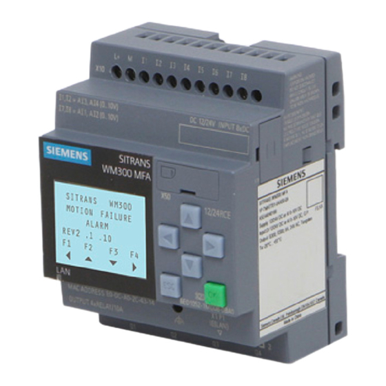
SITRANS WM300 MFA Overview SITRANS WM300 MFA is a highly sensitive, dual setpoint motion sensor alarm unit, used with MSP and XPP probes. The probe detects an increase or decrease in the speed of rotating, reciprocating, or conveying equipment and sends the information to the SITRANS WM300 MFA. - Page 10 SITRANS WM300 MFA Overview SITRANS WM300 MFA Operating Instructions, 08/2018, A5E45090709-AA...
-
Page 11: Installing/Mounting
(50/60 Hz) from nearby power transformers, heater elements, or large industrial motors, because these can affect the probe’s performance. An additional remote display can be connected to the SITRANS WM300 MFA for access to the unit within an enclosure. SITRANS WM300 MFA... -
Page 12: Proper Mounting
Do not mount SITRANS WM300 MFA in direct sunlight. The SITRANS WM300 MFA can be DIN or wall mounted. In a stand-alone enclosure or panel arrangement, the device can use a power transformer to take AC to DC voltage. An... -
Page 13: Mounting Details
Installing/mounting 3.4 Mounting Details Mounting Details To mount the SITRANS WM300 MFA or other components, slide the DIN rail mounting clips outside of the enclosure and to the mounting holes. ① Mounting slide SITRANS WM300 MFA Operating Instructions, 08/2018, A5E45090709-AA... - Page 14 Installing/mounting 3.4 Mounting Details For wall mounting slide the tabs out and mount to the wall/post with M4 screws. ① Mounting slide SITRANS WM300 MFA Operating Instructions, 08/2018, A5E45090709-AA...
- Page 15 95 (3.75) ∅ probe clearance hole ③ Panel cutout ④ Probe flange ● For high temperature and corrosion resistant applications ● 304 stainless steel body comes with stainless steel clamp and silicone gasket SITRANS WM300 MFA Operating Instructions, 08/2018, A5E45090709-AA...
-
Page 16: Wiring
Installing/mounting 3.5 Wiring Wiring Where possible, the probe components should be interconnected via flexible conduit. This allows for easier removal or adjustment of the probe and mounting flange assembly. SITRANS WM300 MFA Operating Instructions, 08/2018, A5E45090709-AA... - Page 17 Installing/mounting 3.5 Wiring SITRANS WM300 MFA Operating Instructions, 08/2018, A5E45090709-AA...
- Page 18 Installing/mounting 3.5 Wiring Note RMA not required for use with MSP-7. Proper switch selection must be made to ensure correct signal conditioning. Improper switch selection may damage the device. SITRANS WM300 MFA Operating Instructions, 08/2018, A5E45090709-AA...
-
Page 19: Connecting
See Cable length from RMA or IMA to WM300 MFA (Page 23) for cable lengths from RMA to main group. Teflon is a registered trademark of E.I. du Pont de Nemours and Company SITRANS WM300 MFA Operating Instructions, 08/2018, A5E45090709-AA... -
Page 20: Msp-12 Probe With Rma (Internally Mounted Pre-Amplifier)
● Wire can be run in conduit common to motor supply or control wiring. Connection to probe terminals can be made under probe cap. See cable lengths (Page 23)for maximum separation from probe to RMA. SITRANS WM300 MFA Operating Instructions, 08/2018, A5E45090709-AA... -
Page 21: Xpp-5 With Rma (Internally Mounted Pre-Amplifier)
● XPP-5 cable must be run in dedicated, approved metal conduit, boxes and fittings and to procedures in accordance with all governing regulations. See Cable length from RMA or IMA to WM300 MFA (Page 23) for cable lengths from probe at SITRANS WM300 MFA. See cable lengths for maximum separation from probe to RMA. -
Page 22: Msp-7 With Ima (Internally Mounted Pre-Amplifier)
MSP-7 with IMA (internally mounted pre-amplifier) Wire can be run in conduit. Connection to probe terminals can be made under probe cap. See cable lengths (Page 23) for maximum separation from probe to SITRANS WM300 MFA. WARNING Unsuitable cables, cable glands and/or plugs Risk of explosion in hazardous areas. -
Page 23: Cable Length From Rma Or Ima To Wm300 Mfa
Cable length from RMA or IMA to WM300 MFA Wire gauge Length in feet Length in meters 22 AWG (0.34 mm 2 500 18 AWG (0.75 mm 5 000 1 520 12 AWG (4 mm 25 000 7 600 SITRANS WM300 MFA Operating Instructions, 08/2018, A5E45090709-AA... -
Page 24: Interconnection Diagram For Xpp-5
Connecting 4.1 Interconnection 4.1.6 Interconnection Diagram for XPP-5 SITRANS WM300 MFA Operating Instructions, 08/2018, A5E45090709-AA... - Page 25 Connecting 4.1 Interconnection SITRANS WM300 MFA Operating Instructions, 08/2018, A5E45090709-AA...
-
Page 26: Connection To Power
A standard LOGO! power module can be used to convert AC to DC power. If 24VDC power is already available in the installation cabinet, connect it directly to the SITRANS WM300 MFA. Typical LOGO! power module SITRANS WM300 MFA Operating Instructions, 08/2018, A5E45090709-AA... - Page 27 ● Relay contact terminals are for use with equipment that has no accessible live parts and wiring that has insulation suitable for at least 250 V. The maximum allowable working voltage between adjacent relay contacts should be 250 V. SITRANS WM300 MFA Operating Instructions, 08/2018, A5E45090709-AA...
- Page 28 Connecting 4.2 Connection to Power SITRANS WM300 MFA Operating Instructions, 08/2018, A5E45090709-AA...
-
Page 29: Service And Maintenance
Calibration The probe and pre-amplifier require no calibration. Connect the probe, pre-amp (if required), and SITRANS WM300 MFA as shown in the Interconnection (Page 19) chapter. Connect the SITRANS WM300 MFA to power as shown in the Connection to Power (Page 26) diagram. - Page 30 Service and maintenance 5.2 Maintenance SITRANS WM300 MFA Operating Instructions, 08/2018, A5E45090709-AA...
-
Page 31: Parameter Assignment
Parameter assignment Menu structure SITRANS WM300 MFA Operating Instructions, 08/2018, A5E45090709-AA... -
Page 32: Motion Failure Alarm
Parameter assignment 6.2 Motion failure alarm Motion failure alarm The table below is a detailed chart of the inputs on the SITRANS WM300 MFA for all functions. Details include the slow speed and standard speed applications with their corresponding outputs. - Page 33 Parameter assignment 6.2 Motion failure alarm Setup of the SITRANS WM300 MFA using the HMI of the device and four button keys. Input Requirements Input I1 – activates a “Reset” of all outputs after an alarm. Input l1 can be used in the two applications listed below: ●...
-
Page 34: 6.3 Start Up Delay
Start up delay = ON I2 = Hi (active Hi transition from Lo – Hi) Input I2 = 1 Enable (momentary transition from Lo - Hi – Lo) Input I2 = 0 Disabled SITRANS WM300 MFA Operating Instructions, 08/2018, A5E45090709-AA... -
Page 35: Start Up Delay (P002)
Values Startup Delay = ON I2 = Hi (Active Hi transition from Lo – Hi) Input I2 = 1 Enable (Momentary transition from Lo - Hi – Lo) Input I2 = 0 Disabled SITRANS WM300 MFA Operating Instructions, 08/2018, A5E45090709-AA... -
Page 36: Alarm Delay
When value = > 0 then output relays are held maintained (Hi) for the set time period to allow system to achieve process speed. Values Alarm Delay = ON P003 ≥ 1 (1 = 1.00 Seconds) Note Typically used for a slow speed process, but compatible with standard operating functions. SITRANS WM300 MFA Operating Instructions, 08/2018, A5E45090709-AA... -
Page 37: Alarm Delay (P004)
Note Typically used for a Slow Speed process, but will work with standard operating functions as well. Values Alarm Delay = ON P004 ≥ 1 (1 = 1.00 Seconds) SITRANS WM300 MFA Operating Instructions, 08/2018, A5E45090709-AA... -
Page 38: Slow Speed
Under speed setpoint indicates when the process speed of the target device has decreased below a safe working speed/rotation. Enter the number of seconds between pulses in an under speed situation. ● P010: xxx seconds SITRANS WM300 MFA Operating Instructions, 08/2018, A5E45090709-AA... -
Page 39: Slow Speed (P011)
Enter the number of seconds between pulses in an over speed situation. ● P011: xxx seconds Values Setpoint 00:00:xx (HH:MM:SS) range 0 ... 399s then resets back to 0 Input I3 – Over Speed alarm output relay Q1 SITRANS WM300 MFA Operating Instructions, 08/2018, A5E45090709-AA... -
Page 40: Slow Speed (P012)
Enter the number of seconds between pulses in an under speed situation. ● P012 = xxx seconds Values Setpoint 00:00:xx (HH:MM:SS) range 0 ... 399s then resets back to 0 Input I4 – Under Speed alarm output relay Q4 SITRANS WM300 MFA Operating Instructions, 08/2018, A5E45090709-AA... -
Page 41: Slow Speed (P013)
0 ... 399s then resets back to 0 Input I4 – Over speed alarm output relay Q2 Run display features seconds between pulses for probe A and B and relay output status. SITRANS WM300 MFA Operating Instructions, 08/2018, A5E45090709-AA... -
Page 42: Process Variable Overview Display
Alarm On = maintained LO output. Probe Input I4 – Output Q2 & Q4 Alarm Off = maintained HI output. Alarm On = maintained LO output. Alarm Off = maintained HI output. Alarm On = maintained LO output. SITRANS WM300 MFA Operating Instructions, 08/2018, A5E45090709-AA... -
Page 43: Standard Version Motion Failure Alarm
The setpoint value (Max Hz) for input I3 represents the 20 mA analog output AQ1. Only set the value if the non-contact tachometer function will be used. ● P020: xxx Seconds ● P021: xxx Seconds SITRANS WM300 MFA Operating Instructions, 08/2018, A5E45090709-AA... -
Page 44: Standard Speed (P022 - P023)
Enter the frequency between pulses in an over speed situation. The setpoint value (Max Hz) for input I4 represents the 20 mA analog output AQ2. Only set the value if the non-contact tachometer function will be used. ● P022: xxx Seconds ● P023: xxx Seconds SITRANS WM300 MFA Operating Instructions, 08/2018, A5E45090709-AA... -
Page 45: 6.6 Tachometer Function
The non-contact tachometer (analog output AQ1 and AQ2) function is for the standard operating mode of the SITRANS WM300 MFA only. The setpoint default for non-contact tachometer is set to a minimum of 16 Hz (4 to 20 mA); therefore, 1 Hz is equal to 1 mA. -
Page 46: Non-Contacting Tachometer (P030)
Standard operating setpoints must be programmed between 1 to 10% only. A setpoint of 0% (which can be set by user interface) will result in an alarm condition, Q3 or Q4 set to failsafe (Lo level) SITRANS WM300 MFA Operating Instructions, 08/2018, A5E45090709-AA... -
Page 47: Maximum Frequency Setpoint (P041 - P042)
Input I4, applied to the same mechanical equipment being monitored. ● For example: I3 maximum Hz = 60 Hz I5 maximum Hz = 30 Hz Alarm setpoint = 10 % SITRANS WM300 MFA Operating Instructions, 08/2018, A5E45090709-AA... - Page 48 ● P041: xxx Hz ● P042: xxx Hz Note In the event both sensors do not monitor the same frequency, the maximum frequency setpoints can be different. The programming calculates the setpoint difference in percentage (%). SITRANS WM300 MFA Operating Instructions, 08/2018, A5E45090709-AA...
-
Page 49: Differential Alarm Setpoints (P043 - P044)
Note Each channel is programmed independently due to variation in frequency based on a target RPM or the number of targets on two different rotating shafts. SITRANS WM300 MFA Operating Instructions, 08/2018, A5E45090709-AA... -
Page 50: Operator Display
Only one of these displays will be active, each display selected is based on which functions have been Enabled. Tachometer function disabled differential speed Tachometer function enabled differential speed disabled disabled Tachometer function enabled differential speed display SITRANS WM300 MFA Operating Instructions, 08/2018, A5E45090709-AA... - Page 51 6.7 Differential speed detection Tachometer function enabled differential speed enabled Note When the non-contact tachometer and the differential speed functions enabled, the display alternates between the over/under speed alarm and non-contact tachometer screens. SITRANS WM300 MFA Operating Instructions, 08/2018, A5E45090709-AA...
- Page 52 Parameter assignment 6.7 Differential speed detection SITRANS WM300 MFA Operating Instructions, 08/2018, A5E45090709-AA...
-
Page 53: Troubleshooting
Operator display screen after power failure or power cycle Following the commissioning of the SITRANS WM300 MFA, the final display is the overview of the relay status and process variables. The F4 key or equivalent is pressed, the device will reset back to the initial start-up display. - Page 54 Troubleshooting 7.1 Troubleshooting SITRANS WM300 MFA Operating Instructions, 08/2018, A5E45090709-AA...
-
Page 55: Technical Data
Technical data Note Device specifications Siemens makes every attempt to ensure the accuracy of these specifications but reserves the right to change them at any time. Safety Note Note Always use product in accordance with specifications. Power ● 10.8 ... 28.8 V DC, 25 ... 165 mA ●... -
Page 56: Inputs
● 30 ... 0.0025 ppm (between pulses: 2 ... 400 seconds) Customer supplied sensor voltage range ● 5 ... 32 VDC Note Please see input specifications for voltage range details. Dynamic range ● 0...10 000 ppm SITRANS WM300 MFA Operating Instructions, 08/2018, A5E45090709-AA... -
Page 57: Design
-50 ... 260 °C (-58 ... 500 °F) 1.4 kg (3 lb) MSP-9 -50 ... 260 °C (-58 ... 500 °F) 1.8 kg (4 lb) MSP-7 -40 ... 60 °C (-40 ... 140 °F) 1.4 kg (3 lb) SITRANS WM300 MFA Operating Instructions, 08/2018, A5E45090709-AA... -
Page 59: Dimension Drawings
Dimension drawings SITRANS WM300 MFA dimensions Dimensions in mm (inch) ① Bus port cover (remove for NCT module integration) SITRANS WM300 MFA Operating Instructions, 08/2018, A5E45090709-AA... - Page 60 Dimension drawings 9.1 SITRANS WM300 MFA dimensions Dimensions in mm (inch) Note • Non-metallic enclosure does not provide grounding between conduit connections: use grounding type bushings and jumpers. • Use only approved, suitable size hubs for watertight application. SITRANS WM300 MFA...
-
Page 61: High Temperature Probe Msp-3
Gasket ⑥ Cap c/w 1/2" NPT conduit entrance ● Cast aluminum body comes with cast aluminum cap and zinc flange, zinc plated locknut, and silicone rubber gasket. ● See Mounting Details (Page 13) SITRANS WM300 MFA Operating Instructions, 08/2018, A5E45090709-AA... -
Page 62: Stainless Steel Probe Msp-9
Dimension drawings 9.3 Stainless Steel Probe MSP-9 Stainless Steel Probe MSP-9 Dimensions in mm (inch) ① Gasket ② Cap c/w 0.875∅ holes (22 mm) ● Stainless steel body and mounting flange SITRANS WM300 MFA Operating Instructions, 08/2018, A5E45090709-AA... -
Page 63: Standard Probe Msp-12 And Msp-7
Probe body ⑤ Gasket ⑥ Cap c/w ½" NPT conduit entrance ● Aluminum body comes with die-cast aluminum cap and zinc flange, zinc plated locknut, and neoprene gasket. ● See Mounting Details (Page 13) SITRANS WM300 MFA Operating Instructions, 08/2018, A5E45090709-AA... -
Page 64: Hazardous Locations Xpp-5
– Class I, Div. 1, Groups A, B, C, and D – Class II, Div. 1, Groups E, F, and G – Class III ● Aluminum body with die-cast flange and zinc-plated locknut. ● Pre-amp and cable potted in the probe's body. SITRANS WM300 MFA Operating Instructions, 08/2018, A5E45090709-AA... - Page 65 Dimension drawings 9.5 Hazardous Locations XPP-5 SITRANS WM300 MFA Operating Instructions, 08/2018, A5E45090709-AA...
-
Page 67: Technical Reference
Principles of Operation SITRANS WM300 MFA SITRANS WM300 MFA is a highly sensitive, dual setpoint motion sensor alarm unit, used with MSP and XPP probes. The probe detects an increase or decrease in the speed of rotating, reciprocating, or conveying equipment and sends the information to the SITRANS WM300 MFA. - Page 68 10 m/minute (35 ft/minute): with a velocity of 0.61 m/minute (2 ft/minute), a maximum gap of 31 mm (1.25 inch) is possible. Note 25.4 mm = 1 inch and 0.305 m = 1 ft SITRANS WM300 MFA Operating Instructions, 08/2018, A5E45090709-AA...
- Page 69 The SITRANS WM300 MFA provides a short circuit protected, +24 V DC unregulated supply to the preamp. The rate at which the pulses are received by the SITRANS WM300 MFA is compared to a setpoint reference signal from the setpoint programmed.
- Page 70 Input I2 must realize a transition from "Lo - Hi - Lo" in order to initiate the internal timer used to maintain the output relay closed. If the monitored equipment does not reach normal operating speed within the set time period, the relays will de-energize creating a failsafe alarm condition. SITRANS WM300 MFA Operating Instructions, 08/2018, A5E45090709-AA...
-
Page 71: Applications
Applications Bucket Elevators Dimensions in mm (inch) SITRANS WM300 MFA Operating Instructions, 08/2018, A5E45090709-AA... -
Page 72: Bucket Elevator
Applications B.2 Bucket Elevator Figure A Dimensions in mm (inch) Bucket Elevator SITRANS WM300 MFA Operating Instructions, 08/2018, A5E45090709-AA... -
Page 73: Shafts
Where conditions prevent the sensing of buckets, a belt pulley or paddle mounted on an exposed shaft end, preferably the tail pulley, may be used. SITRANS WM300 MFA Operating Instructions, 08/2018, A5E45090709-AA... -
Page 74: Rotating Shaft Of Rotary Feeder
Applications B.4 Rotating Shaft of Rotary Feeder Rotating Shaft of Rotary Feeder Drive Sprocket on Rotary Feeder SITRANS WM300 MFA Operating Instructions, 08/2018, A5E45090709-AA... -
Page 75: Belt Conveyors
Arrows indicate permissible placement range of the probe A ferrous mass added behind the flight of a screw conveyor, where it passes the probe aids Borderline Operation. This mass must be added for all non-ferrous screws. SITRANS WM300 MFA Operating Instructions, 08/2018, A5E45090709-AA... -
Page 76: Screw Conveyor Flights
Applications B.8 Screw Conveyor Flights Screw Conveyor Flights End Bearing on Screw Conveyor SITRANS WM300 MFA Operating Instructions, 08/2018, A5E45090709-AA... -
Page 77: Non-Ferrous Window
The probe may not touch the window if temperatures are in excess of 60 °C (140 °F) when using the low temperature probes or 260 °C (500 °F) when using the high temperature probes. SITRANS WM300 MFA Operating Instructions, 08/2018, A5E45090709-AA... - Page 78 Applications B.10 Non-ferrous Window SITRANS WM300 MFA Operating Instructions, 08/2018, A5E45090709-AA...
-
Page 79: Support
In addition to our documentation, Siemens provides a comprehensive support solution at: ● Partner (http://www.automation.siemens.com/partner) Personal contact If you have additional questions about the device, please contact your Siemens personal contact at: ● Support request (http://www.siemens.com/automation/support-request) To find the personal contact for your product, go to "All Products and Branches" and select "Products &... - Page 80 Support C.2 Certificates SITRANS WM300 MFA Operating Instructions, 08/2018, A5E45090709-AA...
-
Page 81: Index
XPP-5, 64 mounting details, 15 Document history, 7 Documentation, 79 Drive sprocket on rotary feeder, 74 Dynamic range, 56 Non-ferrous window, 77 End bearing on screw conveyor, 76 Operating conditions, 57 Operating Instructions, 79 SITRANS WM300 MFA Operating Instructions, 08/2018, A5E45090709-AA... - Page 82 Shafts, 73 Support, 79 Support request, 79 Technical data, 55 approvals, 57 construction, 57 operating conditions, 57 outputs, 55 performance, 56 power, 55 Technical support Partner, 79 Technical Support, 79 Personal contact, 79 SITRANS WM300 MFA Operating Instructions, 08/2018, A5E45090709-AA...
Need help?
Do you have a question about the SITRANS WM300 MFA and is the answer not in the manual?
Questions and answers