Table of Contents
Advertisement
Quick Links
SINUMERIK SINUMERIK 802D sl Cylindrical grinding
SINUMERIK
SINUMERIK 802D sl
Cylindrical grinding
Programming and Operating Manual
Valid for
Control
SINUMERIK 802D sl G/N
07/2009
6FC5398-4CP10-2BA0
software version
1.4
Preface
______________
Description
______________
Software interface
Turning on, reference
______________
point approach
______________
Define
______________
Manual mode
______________
Automatic mode
______________
Part programming
______________
System
______________
Cycles
______________
Programming
______________
Network operation
______________
Data Backup
______________
PLC diagnostics
______________
Application Examples
______________
Appendix
1
2
3
4
5
6
7
8
9
10
11
12
13
14
A
Advertisement
Table of Contents

Related Manuals for Siemens SINUMERIK 802D


Summary of Contents for Siemens SINUMERIK 802D
- Page 1 Preface SINUMERIK SINUMERIK 802D sl Cylindrical grinding ______________ Description ______________ Software interface SINUMERIK Turning on, reference ______________ point approach SINUMERIK 802D sl ______________ Cylindrical grinding Define ______________ Manual mode Programming and Operating Manual ______________ Automatic mode ______________ Part programming ______________...
- Page 2 Note the following: WARNING Siemens products may only be used for the applications described in the catalog and in the relevant technical documentation. If products and components from other manufacturers are used, these must be recommended or approved by Siemens. Proper transport, storage, installation, assembly, commissioning, operation and maintenance are required to ensure that the products operate safely and without any problems.
-
Page 3: Preface
● Researching documentation online Information on DOConCD and direct access to the publications in DOConWEB. ● Compiling individual documentation on the basis of Siemens contents with the My Documentation Manager (MDM), refer to http://www.siemens.com/mdm My Documentation Manager provides you with a range of features for generating your own machine documentation. - Page 4 If you have any technical questions, please contact our hotline: Europe / Africa Phone +49 180 5050 222 +49 180 5050 223 € 0.14/min. from German landlines, mobile phone prices may differ. Internet http://www.siemens.com/automation/support-request America Phone +1 423 262 2522 +1 423 262 2200 E-mail mailto:techsupport.sea@siemens.com...
- Page 5 The EC Declaration of Conformity for the EMC Directive can be found/obtained ● on the internet: http://support.automation.siemens.com under the product/order No. 15263595 ● at the relevant regional office of the I DT MC Business Unit of Siemens AG. Cylindrical grinding Programming and Operating Manual, 07/2009, 6FC5398-4CP10-2BA0...
- Page 6 Preface Cylindrical grinding Programming and Operating Manual, 07/2009, 6FC5398-4CP10-2BA0...
-
Page 7: Table Of Contents
Table of contents Preface ..............................3 Description............................... 13 Control and display elements.......................13 Key definition of the full CNC keyboard (vertical format).............15 Key definition of the machine control panel .................17 Coordinate systems ........................19 Software interface............................ 23 Screen layout ..........................23 Standard softkeys ........................27 Operating areas ...........................28 The help system...........................30 Turning on, reference point approach ...................... - Page 8 Table of contents Selection and start of a part program..................84 Block search..........................86 Simultaneous recording ......................89 Stop / cancel a part program....................... 92 Reapproach after cancellation ....................93 Repositioning after interruption ....................94 Execute from external ......................... 95 Part programming ............................
- Page 9 Table of contents 9.11 Oblique plunge-cutting – CYCLE413 ..................185 9.12 Radius grinding – CYCLE414 ....................190 9.13 Reciprocating – CYCLE415 .......................194 9.14 Dressing and profiling – CYCLE416 ..................200 9.15 General workpiece data – CYCLE420 ..................203 9.16 Dressing with profile roller - CYCLE430 ..................207 9.17 Selection of the grinding wheel peripheral speed - CYCLE446..........209 9.18...
- Page 10 Table of contents 10.4.2 Spindle speed limitation: G25, G26 ..................279 10.4.3 Spindle positioning: SPOS ......................280 10.4.4 Gear stages..........................281 10.4.5 2. Spindle ..........................281 10.5 Special functions ........................283 10.5.1 Constant cutting rate: G96, G97 ....................283 10.5.2 Rounding, chamfer........................
- Page 11 Table of contents 11.3.4 Working on the basis of a network connection ................346 11.3.5 Sharing directories ........................347 11.3.6 Connecting / disconnecting network drives ................348 Data Backup ............................351 12.1 Data transfer via RS232 interface....................351 12.2 Creating / reading in / reading out a start-up archive ..............353 12.3 Reading in / reading out PLC projects ..................356 12.4...
- Page 12 Table of contents Cylindrical grinding Programming and Operating Manual, 07/2009, 6FC5398-4CP10-2BA0...
-
Page 13: Description
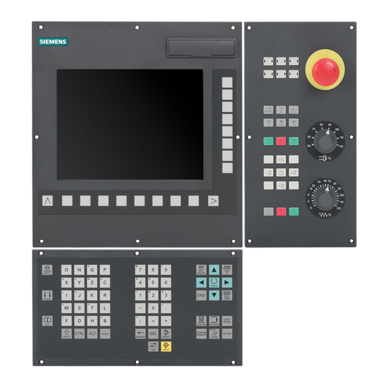
Description Control and display elements Operator control elements The defined functions are called up via the horizontal and vertical softkeys. For a description, please refer to this manual: Figure 1-1 CNC operator panel LED displays on the CNC operator panel (PCU) The following LEDs are installed on the CNC operator panel. - Page 14 Description 1.1 Control and display elements References You can find information on error description in the SINUMERIK 802D sl Diagnostics Manual Cylindrical grinding Programming and Operating Manual, 07/2009, 6FC5398-4CP10-2BA0...
-
Page 15: Key Definition Of The Full Cnc Keyboard (Vertical Format)
Description 1.2 Key definition of the full CNC keyboard (vertical format) Key definition of the full CNC keyboard (vertical format) Cylindrical grinding Programming and Operating Manual, 07/2009, 6FC5398-4CP10-2BA0... - Page 16 Description 1.2 Key definition of the full CNC keyboard (vertical format) Hot keys In the part program editor and in the input fields of the HMI, the following functions can be carried out with certain key combinations on the full CNC keyboard: Keystroke combination Function <CTRL>...
-
Page 17: Key Definition Of The Machine Control Panel
Description 1.3 Key definition of the machine control panel Key definition of the machine control panel Cylindrical grinding Programming and Operating Manual, 07/2009, 6FC5398-4CP10-2BA0... - Page 18 Description 1.3 Key definition of the machine control panel Note This documentation assumes an 802D standard machine control panel (MCP). Should you use a different MCP, the operation may be other than described herein. Cylindrical grinding Programming and Operating Manual, 07/2009, 6FC5398-4CP10-2BA0...
-
Page 19: Coordinate Systems
Description 1.4 Coordinate systems Coordinate systems As a rule, a coordinate system is formed from three mutually perpendicular coordinate axes. The positive directions of the coordinate axes are defined using the so-called "3-finger rule" of the right hand. The coordinate system is related to the workpiece and programming takes place independently of whether the tool or the workpiece is being traversed. - Page 20 Description 1.4 Coordinate systems The origin of this coordinate system is the machine zero. This point is only a reference point which is defined by the machine manufacturer. It does not have to be approachable. The traversing range of the machine axes can by in the negative range. Workpiece coordinate system (WCS) To describe the geometry of a workpiece in the workpiece program, a right-handed, right- angled coordinate system is also used.
- Page 21 Description 1.4 Coordinate systems Clamping the workpiece For machining, the workpiece is clamped on the machine. The workpiece must be aligned such that the axes of the workpiece coordinate system run in parallel with those of the machine. Any resulting offset of the machine zero with reference to the workpiece zero is determined along the Z axis and entered in a data area intended for the settable work offset.
- Page 22 Description 1.4 Coordinate systems Cylindrical grinding Programming and Operating Manual, 07/2009, 6FC5398-4CP10-2BA0...
-
Page 23: Software Interface
Software interface Screen layout Figure 2-1 Screen layout The screen is divided into the following main areas: ● Status area ● Application area ● Note and softkey area Status area Figure 2-2 Status area Cylindrical grinding Programming and Operating Manual, 07/2009, 6FC5398-4CP10-2BA0... - Page 24 Software interface 2.1 Screen layout Table 2- 1 Explanation of the screen controls in the status area Numbering Display Icon Significance ① Active operating area Position (operating area key <POSITION>) System (operating area key <SYSTEM>) Program (operating area key <PROGRAM>) Program Manager (operating area key <PROGRAM MANAGER>) Parameter (operating area key <OFFSET...
- Page 25 Software interface 2.1 Screen layout Numbering Display Icon Significance AUTOMATIC ③ Alarm and message line In addition, the following is displayed: 1. Alarm number with alarm text, or 2. Message text ④ Selected part program (main program) ⑤ Program state RESET Program canceled / default state Program is running...
- Page 26 Software interface 2.1 Screen layout Table 2- 2 Explanation of the screen controls in the note and softkey area Screen item Display Significance ① RECALL symbol Pressing the <RECALL> key lets you return to the higher menu level. ② Information line Displays notes and information for the operator and fault states ③...
-
Page 27: Standard Softkeys
Software interface 2.2 Standard softkeys Standard softkeys Use this softkey to close the screen. Use this softkey to cancel the input; the window is closed. Selecting this softkey will complete your input and start the calculation. Selecting this softkey will complete your input and accept the values you have entered. This function is used to switch the screenform from diameter programming to radius programming. -
Page 28: Operating Areas
Software interface 2.3 Operating areas Operating areas The functions of the control system can be carried out in the following operating areas: POSITION Machine operation OFFSET PARAM Entering the compensation values and setting data PROGRAM Creation of part programs PROGRAM Part program directory MANAGER SYSTEM... - Page 29 Software interface 2.3 Operating areas Protection levels The SINUMERIK 802D sl provides a concept of protection levels for enabling data areas. The control system is delivered with default passwords for the protection levels 1 to 3. Protection level 1 Experts password...
-
Page 30: The Help System
Software interface 2.4 The help system The help system Comprehensive online help is stored in the control system. Some help topics are: ● Product brief of all important operating functions ● Overview and product brief of the NC commands ● Explanation of the drive parameters ●... - Page 31 Software interface 2.4 The help system Softkeys This function opens the selected topic. Figure 2-5 Help system: Description of the topic Use this function to select cross references. A cross reference is marked by the characters ">>..<<". This softkey is only displayed if a cross reference is displayed in the application area.
- Page 32 Software interface 2.4 The help system Cylindrical grinding Programming and Operating Manual, 07/2009, 6FC5398-4CP10-2BA0...
-
Page 33: Turning On, Reference Point Approach
Turning on, reference point approach Turning On and Reference Point Approach Note When turning on the SINUMERIK 802D sl and the machine, please also observe the machine documentation, since turning on and reference point approach are machine- dependent functions. Operating sequence First, turn on the power supply of CNC and machine. - Page 34 Turning on, reference point approach 3.1 Turning On and Reference Point Approach Press the arrow keys. If you select the wrong approach direction, no motion is carried out. Approach the reference points for each axis one after the other. You can exit the function by selecting another operating mode ("JOG", "MDA" or "Automatic").
-
Page 35: Define
Define Entering tools and tool offsets Functionality The "OFFSET PARAM" operating area allows you to store the parameters required for machine operation. Operating sequences This function opens the "Tool offset data" window which contains a list of the tools created. Use the cursor keys and the <Page Up>/<Page Down>... - Page 36 Define 4.1 Entering tools and tool offsets Softkeys Clearing the calculated dresser data. Use this softkey to delete the tool. Opens a lower-level menu bar offering all functions required to create and display further tolol data. This function is used to enter - guided by the menu - the nomiinal dimensions and monitoring data of the grinding wheel.
-
Page 37: Create New Tool
Define 4.2 Create new tool Create new tool Functionality The tool offsets consist of various data describing the geometrty, the wear and the tool type. Each tool contains a defined number of parameters, depending on the tool type. Tools are identified by a number (T number). - Page 38 Define 4.2 Create new tool Operating sequences (new tool) This function opens an input screen in which the tool number, tool type, and grinding wheel shape are to be entered or selected. Figure 4-3 New tool Confirm your input using "OK". Figure 4-4 New tool inserted A data record loaded with zero will be included in the tool list.
- Page 39 Define 4.2 Create new tool Note: Cylindrical grinding begins with S2. Flat grinding begins with S1. The conversion is done internally, for an entered value of 1. For standard wheels (vertical and inclined), the D numbers are allocated a fixed meaning (refer to the "compensation values"...
- Page 40 Define 4.2 Create new tool Figure 4-5 Compensation values Cutting edges 7-9 are the three available dressing tools have a fixed allocation to the standard contour cutting edge. Table 4- 1 Allocation of dressers D field Dresser Assignment Dresser 1 Left-hand front cutting edge Dresser 2 Right-hand rear cutting edge...
- Page 41 Define 4.2 Create new tool In the next step, the tool data are to be entered. ● Nominal dimensions for monitoring ● Geometry data ● Technological data ● Data for the dressers Nominal dimensions and monitoring This function opens in input screen into which grinding wheel nominal dimensions and monitoring data are entered.
- Page 42 Define 4.2 Create new tool Geometry data This function is used the enter the wheel geometry for the wheel type selected. Figure 4-7 Geometry example data for a vertical wheel with back-slope The following wheel types are available: ● Vertical wheel without back-slopes (type 1) ●...
- Page 43 Define 4.2 Create new tool Technological data By means of the technological data, the wheel type dependent dressing technology is defined. Figure 4-8 Technology example data for a vertical wheel with back-slope Dresser Use the "1st dresser", "2nd dresser" or "3rd dresser" softkeys to access the dialog box for entering or verifying the dresser data.
- Page 44 Define 4.2 Create new tool The dresser type is selected in the Type toggle field. Fixed dresser: Tile/Diamond Forming rolls 1 to 3 Diamond rolls 1 to 3 Enter the parameters depending on the selection made. Figure 4-10 Forming roll Figure 4-11 Diamond roll Cylindrical grinding...
- Page 45 Define 4.2 Create new tool Parameter tables The function opens a summary of all cutting edge parameters. Note: This function is available only with a password set (Customer). Figure 4-12 The following table contains all cutting edge data. Tool offset data See the chapter "Parameter tables of the tool offset data"...
-
Page 46: Sense Dresser
Define 4.3 Sense dresser Sense dresser Functionality This function is used to determine the dresser positions in the machine for dressers that are used by means of the geometry axes. The axis values are determinded in machine coordinates by the HMI and transmitted to the cycle. Operation The dresser is sensed in JOG mode. - Page 47 Define 4.3 Sense dresser After scratching, the "Save position" softkey is used to read and internally save the axis actual value. The green check mark at the end of the line indicates this action. Thereafter, the second axis is processed. Once all axes have been sensed, press the "Calculate position"...
-
Page 48: Sense Workpiece
Define 4.4 Sense workpiece Sense workpiece Functionality This function is used to detect the workpiece position in the machine with respect to the particular axis. The HMI transmits both axis name and setpoint to the cycle. Operation The workpiece is sensed in JOG mode by scratching the respective axes. The input screen is opened. - Page 49 Define 4.4 Sense workpiece Special features in relation to "Manual Grinding" If you have interrupted manual grinding (Page 54) with the PLC button "Handwheel", the last position of the infeed axis can be calculated in the subsequent "Sense workpiece" > "Calculate position"...
-
Page 50: Shaping/Dressing
Define 4.5 Shaping/dressing Shaping/dressing Functionality This function is used to shape a "raw" grinding wheel without generating an NC program. The procedure always refers to the currently active tool. Operation Shaping is done in JOG mode. The input screen is opened. Figure 4-16 Shaping The required shaper values that are machined in dressing strokes are entered using the... - Page 51 Define 4.5 Shaping/dressing How shaping is executed In the cycle, the shaper allowance is machined first and then all dressing strokes are executed. The current state is shown in the fields. The procedure can be stopped at any time. Press the "Start shaping" softkey to restart the procedure. Values can be modified. Exit the "Shaping"...
-
Page 52: Sense Probe
Define 4.6 Sense probe Sense probe Functionality This function is used to set the measuring position of the probe. The measuring position is set up for each particular workpiece For calibrating, no active tool is required. However, the workpiece must have been set up using a valid tool since the longitudinal alignment position refers to the workpiece and the associated zero shift Operation... - Page 53 Define 4.6 Sense probe The values for the setting value (position in Z axis), feedrate, and approach direction are entered into the input screen. Press the "Set position" softkey to set up the measuring position. The Z axis feeds in probe direction until the workpiece is touched. This position is set as a value and the probe retracts.
-
Page 54: Manual Grinding
Define 4.7 Manual grinding Manual grinding Functionality This function is for grinding (precision grinding) with the handwheel. This function does not require a workpiece program. Operation Manual grinding is done in "Jog" mode. The input screen is opened. Entry of parameters into the input screen for manual grinding (see figure below): ●... - Page 55 Define 4.7 Manual grinding Manual grinding, no reciprocation The figure below shows an input screen with parameters for manual grinding without reciprocation: Figure 4-19 Manual grinding without reciprocation This function starts manual grinding with the handwheel. A prompt appears. Figure 4-20 Prompt Execution of manual grinding with handwheel (without reciprocation).
- Page 56 Define 4.7 Manual grinding Manual grinding, reciprocation The figure below shows an input screen with parameters for manual grinding with reciprocation: Figure 4-21 Manual grinding, with reciprocation If you have selected reciprocation, then you should use this function to enter the reciprocation data (see figure below): Figure 4-22 Manual grinding with reciprocation data in X...
- Page 57 Define 4.7 Manual grinding ● Feedrate X (mm/min) ● Dwell time at reversal point position 2 (in seconds if there is a tool spindle present; otherwise, in revolutions) This function starts manual grinding with the handwheel. The following prompt is displayed: "The selected program will cause the axes to perform a traversing motion! Do you wish to continue?"...
-
Page 58: Program Setting Data
Define 4.8 Program setting data Program setting data Functionality The setting data are used to define the settings for the operating states. These can be changed as necessary. Operating sequence These can be found in the <OFFSET PARAM> operating area. Press the "Setting data"... - Page 59 Define 4.8 Program setting data ● Dry run feed (DRY) The feedrate which can be entered here will be used instead of the programmed feedrate in the AUTOMATIC mode if the "Dry run feed" function is selected. ● Starting angle for thread (SF) For thread cutting, a start position for the spindle is displayed as the start angle.
- Page 60 Define 4.8 Program setting data Times Counters Figure 4-25 Times, Counters Meaning: ● Total parts: Total number of workpieces produced (total actual) ● Parts requested: Number of workpieces required (workpiece setpoint) ● Number of parts: This counter registers the number of all workpieces produced since the starting time.
- Page 61 Define 4.8 Program setting data Use this function to display all setting data for the control system in the form of a list. The setting data are divided up into general, axis-specific and channel-specific data. They can be selected using the following softkey functions: ●...
-
Page 62: Arithmetic Parameter R
Define 4.9 Arithmetic parameter R Arithmetic parameter R Functionality In the "R parameters" start screen, any R parameters that exist within the control system are listed. These global parameters can be set or queried by the programmer of the part program for any purpose in the program and can be changed as required. -
Page 63: User Data
Define 4.10 User data 4.10 User data Functionality The user data is internally processed in the cycles. This data can be changed as necessary. Operating sequences These can be found in the <OFFSET PARAM> operating area. Press the <User data> softkey. This will open the "User data" start screen for the cycles. Figure 4-28 User data Place the cursor bar on the input field to be modified and enter the values. - Page 64 Define 4.10 User data Cylindrical grinding Programming and Operating Manual, 07/2009, 6FC5398-4CP10-2BA0...
-
Page 65: Manual Mode
Manual mode Manual mode Manual mode is supported by the JOG and MDA operating modes. Figure 5-1 JOG menu tree, "Position" operating area Figure 5-2 MDA menu tree, "Position" operating area Cylindrical grinding Programming and Operating Manual, 07/2009, 6FC5398-4CP10-2BA0... -
Page 66: Jog Mode - "Position" Operating Area
Manual mode 5.2 JOG mode - "Position" operating area JOG mode - "Position" operating area Operating sequences Use the "JOG" key on the machine control panel to select the Jog mode. To traverse the axes, press the appropriate key of the X or Z axis. The axes will traverse continuously at the velocity stored in the setting data until the key is released. - Page 67 Manual mode 5.2 JOG mode - "Position" operating area Parameter Table 5- 1 Description of the parameters in the JOG start screen Parameter Explanation Displays the axes existing in the machine coordinate system (MCS) or in the workpiece coordinate system (WCS) If you traverse an axis in the positive (+) or negative () direction, a plus or minus sign will appear in the relevant field.
- Page 68 Manual mode 5.2 JOG mode - "Position" operating area Softkeys Note An explanation of the vertical softkeys can be found in the section on the MDA mode (Page 70). This function is for grinding (precision grinding) with the handwheel. This function does not require a workpiece program.
-
Page 69: Assigning Handwheels
Manual mode 5.2 JOG mode - "Position" operating area 5.2.1 Assigning handwheels Operating sequence Select the "JOG" operating mode. Press the "Handwheel" softkey. The "Handwheel" window appears on the screen. After the window has been opened, all axis identifiers are displayed in the "Axis" column, which simultaneously appear in the softkey bar. -
Page 70: Mda Mode (Manual Input) "Position" Operating Area
Manual mode 5.3 MDA mode (manual input) "Position" operating area MDA mode (manual input) "Position" operating area Functionality In the MDA mode, you can create or execute a part program. CAUTION The Manual mode is subject to the same safety interlocks as the fully automatic mode. Furthermore, the same prerequisites are required as in the fully automatic mode. - Page 71 Manual mode 5.3 MDA mode (manual input) "Position" operating area Parameter Table 5- 2 Description of the parameters in the MDA working window Parameter Explanation Displays the existing axes in the MCS or WCS If you traverse an axis in the positive (+) or negative () direction, a plus or minus sign will appear in the relevant field.
- Page 72 Manual mode 5.3 MDA mode (manual input) "Position" operating area Softkeys An explanation of the horizontal softkeys can be found in the section entitled "Jog mode - Position operating area" (Page 66). The G function window displays G functions whereby each G function is assigned to a group and has a fixed position in the window.
-
Page 73: Teach In (Mda)
Manual mode 5.3 MDA mode (manual input) "Position" operating area 5.3.1 Teach In (MDA) Functionality You can use the "Teach In" function to create and change simple traversing blocks. You can transfer axis position values directly into a newly generated or changed part program record. The axis positions are reached by traversing with the axis direction keys and transferred into the part program. - Page 74 Manual mode 5.3 MDA mode (manual input) "Position" operating area General sequence 1. Use the arrow keys to select the program block that you want to edit or that is to have the new traversing block inserted in front of it. 2.
- Page 75 Manual mode 5.3 MDA mode (manual input) "Position" operating area – "Rapid feed" Figure 5-9 Rapid traverse You traverse the axes and teach-in a rapid traverse block with the approached positions. – "Linear" Figure 5-10 Linear You traverse the axes and teach in a linear block with the approached positions. Cylindrical grinding Programming and Operating Manual, 07/2009, 6FC5398-4CP10-2BA0...
- Page 76 Manual mode 5.3 MDA mode (manual input) "Position" operating area – "Circular" Figure 5-11 Circular You teach in an intermediate point and an end point for a circle. Operation in the "Rapid traverse", "Linear" and "Circular" dialogs 1. Use the axis keys to traverse the axes to the required position that you want to add/change in the part program.
-
Page 77: Automatic Mode
Automatic mode Automatic mode Menu tree Figure 6-1 Automatic menu tree Preconditions The machine is set up for the AUTOMATIC mode according to the specifications of the machine manufacturer. Cylindrical grinding Programming and Operating Manual, 07/2009, 6FC5398-4CP10-2BA0... - Page 78 Automatic mode 6.1 Automatic mode Operating sequence Select Automatic mode by pressing the <Automatic> key on the machine control panel. The Automatic start screen appears, displaying the position, feedrate, spindle, and tool values, as well as the currently active block. Figure 6-2 Automatic start screen Parameter...
- Page 79 Automatic mode 6.1 Automatic mode Parameter Explanation Tool Displays the currently active tool with the current edge number (T..., D...). Current The block display displays seven subsequent blocks of the currently active part block program. The display of one block is limited to the width of the window. If several blocks are to be executed in quick succession, you are recommended to switch to the "Program progress"...
- Page 80 Automatic mode 6.1 Automatic mode Softkeys Opens the G functions window to display all G functions currently active. The G functions window displays all the G functions that are currently active with each G function assigned to a group and having a fixed position in the window. Figure 6-3 G Functions Use the <PageUp>...
- Page 81 Automatic mode 6.1 Automatic mode The program control softkeys are displayed (e.g. "Skip block", "Program test"). ● "Program test": If "Program test" is selected, the output of setpoints to axes and spindles is disabled. The set point display "simulates" the traverse movements. ●...
- Page 82 Automatic mode 6.1 Automatic mode Displays the "Regrinding" window. Enter the compensation values for regrinding. When you select "OK", the parameters will be inserted in the program after the selected block. It is possible to simultaneously record when the part program is executed (see Chapter "Simultaneously recording (Page 89)").
-
Page 83: Machining Offset
Automatic mode 6.2 Machining offset Machining offset Functionality Fine offsets can be entered in X and Z, globally for each seat or individually for a specific seat. From then on, these offsets will always be used for the grinding work (seat). Operating sequence The Automatic start screen will display a window for the machining offsets. -
Page 84: Selection And Start Of A Part Program
Automatic mode 6.3 Selection and start of a part program Selection and start of a part program Functionality Before starting the program, make sure that both the control system and the machine are set up. Observe the relevant safety notes of the machine manufacturer. Operating sequence Select Automatic mode by pressing the "Automatic"... - Page 85 Automatic mode 6.3 Selection and start of a part program If desired, here you can specify how you want the program to be executed. Figure 6-6 Program control Press "NC START" to start executing the part program. Cylindrical grinding Programming and Operating Manual, 07/2009, 6FC5398-4CP10-2BA0...
-
Page 86: Block Search
Automatic mode 6.4 Block search Block search Operating sequence Requirement:The desired program has already been selected and the control system is in the RESET state. The block search function provides advance of the program to the required block in the part program. - Page 87 Automatic mode 6.4 Block search Use this softkey to perform the block search by entering a term you are looking for. Figure 6-8 Entering the searched term You can use the toggle field to define the starting position for the search. Search result The required part program block is displayed in the "Current block"...
- Page 88 Automatic mode 6.4 Block search Regrinding "Regrinding" enables you to remachine the "seat" of a workpiece that has already been machined, either with or without an offset, but always with the same technological values. Displays the "Regrinding" window. Figure 6-9 Regrinding Enter the compensation values for regrinding.
-
Page 89: Simultaneous Recording
Automatic mode 6.5 Simultaneous recording Simultaneous recording Operating sequence You have selected a part program to be executed and have pressed <NC START>. Execution of the part program is simultaneously recorded on the HMI using the "Simultaneous recording" function. Figure 6-10 "Simultaneous recording"... - Page 90 Automatic mode 6.5 Simultaneous recording ● "Delete window" ● "Cursor" – "Set cursor" – "Cursor fine", "Cursor coarse", "Cursor very coarse" When the cursor keys are pressed, the cross hair moves in small, average or large steps. Exit the "Simultaneous recording" function. "Display areas"...
- Page 91 Automatic mode 6.5 Simultaneous recording Figure 6-12 Display area "Window max" Operating sequence to set and save the display area 1. You have selected an area in the simulation view. 2. Press the "Display areas" function. 3. Press the "Window min/max" so that a maximum display can be see according to the screen "Display areas "Window max".
-
Page 92: Stop / Cancel A Part Program
Automatic mode 6.6 Stop / cancel a part program Stop / cancel a part program Operating sequence With <NC STOP> the execution of a part program is interrupted. The interrupted machining can be continued with <NC START>. Use <RESET> to abort the program currently running. By pressing <NC START>... -
Page 93: Reapproach After Cancellation
Automatic mode 6.7 Reapproach after cancellation Reapproach after cancellation After a program cancellation (RESET), you can retract the tool from the contour in manual mode (JOG). Operating sequence Select mode <AUTOMATIC> mode. Opening the "Block search" window for loading the interruption point. The interruption point is loaded. -
Page 94: Repositioning After Interruption
Automatic mode 6.8 Repositioning after interruption Repositioning after interruption After interrupting the program (<NC STOP>), you can retract the tool from the contour in manual mode (JOG). The control saves the coordinates of the point of interruption. The distances traversed are displayed. Operating sequence Select <AUTOMATIC>... -
Page 95: Execute From External
In <AUTOMATIC> mode > <PROGRAM MANAGER> operating area, the following interfaces are available for external execution of programs: Customer CompactFlash card RCS connection for external execution via network (only for SINUMERIK 802D sl pro) Manufacturer's drive USB FlashDrive Start in the following start screen of the Program Manager: Figure 6-13 The "Program Manager"... - Page 96 Automatic mode 6.9 Execute from external Operating sequence, execution from customer CompactFlash Card or USB FlashDrive Requirement: The control system is in the "Reset" state. Select the <AUTOMATIC> mode key . Press the <PROGRAM MANAGER> key on the machine control panel. Press the "Customer CF card"...
- Page 97 Automatic mode 6.9 Execute from external 4. Programming device/PC: – Activate the drive/directory for network operation. 5. Programming device/PC: – Establish an Ethernet connection to the control. 6. Control: (see "Connecting / disconnecting a network drive") – Connect to the directory activated on the programming device/PC using the following dialog: Operating area <SYSTEM>...
- Page 98 Automatic mode 6.9 Execute from external Cylindrical grinding Programming and Operating Manual, 07/2009, 6FC5398-4CP10-2BA0...
-
Page 99: Part Programming
Part programming Part programming overview Menu tree Figure 7-1 "Program Manager" menu tree Functionality The PROGRAM MANAGER operating area is the management area for workpiece programs in the control system. In this area, programs can be created, opened for modification, selected for execution, copied, and inserted. - Page 100 Part programming 7.1 Part programming overview Operating sequence Press the <PROGRAM MANAGER> key to open the program directory. Figure 7-2 The "Program Manager" start screen Use the cursor keys to navigate in the program directory. To find program names quickly, simply type the initial letter of the program name.
- Page 101 Part programming 7.1 Part programming overview Note Selecting individual files: Position the cursor on the corresponding file and press the <Select> key. The selected line will change its color. If you press the <Select> key once more, the selection is canceled. This function will enter one or several files in a list of files (called 'clipboard') to be copied.
- Page 102 This softkey is needed in connection with the work in the network. Additional information is provided in Chapter, network operation (only for SINUMERIK 802D sl pro). The functions required for reading out/reading in files are provided via the RS232 interface.
-
Page 103: Enter New Program
Part programming 7.2 Enter new program Enter new program Operating sequences You have selected the PROGRAM MANAGER operating area. Use the "NC directory" softkeys to select the storage location for the new program. Press "New". You have the choice of the following options: Figure 7-3 New program After presssing the softkey "New directory"... -
Page 104: Editing The Part Program
Part programming 7.3 Editing the part program Editing the part program Functionality A part program can only be edited if it is currently not being executed. Any modifications to the part program are stored immediately. Figure 7-4 Program editor start screen Menu tree Figure 7-5 Program menu tree (cylindrical grinding) - Page 105 Part programming 7.3 Editing the part program Operating sequence In the PROGRAM MANAGER operating area, select the program to be edited. Press the "Open" softkey. The selected program will open. Softkeys Use this softkey to edit a file. Use this softkey to execute the selected file. Use this softkey to select a text segment up to the current cursor position (alternatively: <CTRL+B>) Use this softkey to copy a selected block to the clipboard (alternatively: <CTRL+C>)
- Page 106 Part programming 7.3 Editing the part program Cylindrical grinding Programming and Operating Manual, 07/2009, 6FC5398-4CP10-2BA0...
-
Page 107: System
System "System" operating area Functionality The SYSTEM operating area includes functions required for parameterizing and analyzing the NCK, the PLC and the drive. Depending on the functions selected, the horizontal and the vertical softkey bars change. The menu tree shown below only includes the horizontal softkeys. Menu tree Figure 8-1 System menu tree... - Page 108 ● User password It is possible to change certain data corresponding to the access levels. If you do not know the password, access will be denied. Note Also see SINUMERIK 802D sl "Lists". Cylindrical grinding Programming and Operating Manual, 07/2009, 6FC5398-4CP10-2BA0...
- Page 109 System 8.1 "System" operating area Figure 8-3 Entering the password After selecting the "Accept" softkey, the password is set. Use "Abort" to return without any action to the "System" start screen. "Change Password" Figure 8-4 Change password Depending on the access right, various possibilities are offered in the softkey bar to change the password.
- Page 110 System 8.1 "System" operating area Resetting the credential User network log-in Use "Change language" to select the user interface language. Figure 8-5 User interface language Use the cursor keys to select the language and confirm it by pressing "OK". Note The HMI is automatically restarted when a new language is selected.
- Page 111 System 8.1 "System" operating area "Save data" This function will save the contents of the volatile memory into a nonvolatile memory area. Requirement: There is no program currently executed. Do not carry out any operator actions while the data backup is running! The NC and PLC data are backed up.
-
Page 112: System - "Start-Up" Softkeys
System 8.2 SYSTEM - "Start-up" softkeys SYSTEM - "Start-up" softkeys Commissioning Use this softkey to select the NC power-up mode. Select the desired mode using the cursor. ● Normal power-up The system is restarted ● Power-up with default data The display machine data are reset to their standard values (restores the initial state when originally supplied) ●... -
Page 113: System - "Machine Data" Softkeys
You will find a description of the machine data in the following manufacturers´ documents: SINUMERIK 802D sl List Manual SINUMERIK 802D sl Function Manual for turning, milling, nibbling Machine data Any changes in the machine data have a substantial influence on the machine. - Page 114 System 8.3 SYSTEM - "Machine data" softkeys General machine data Open the "General machine data" window. Use the Page Up / Page Down keys to browse forward / backward. Figure 8-7 General machine data Executes a warm restart at the control. "Find"...
- Page 115 System 8.3 SYSTEM - "Machine data" softkeys This function provides various display filters for the active machine data group. Further softkeys are provided: ● "Expert": Use this softkey to select all data groups of the expert mode for display. ● "Filter active": Use this softkey to activate all data groups selected. After you have quit the window, you will only see the selected data on the machine data display.
- Page 116 System 8.3 SYSTEM - "Machine data" softkeys Use "Axis +" or "Axis " to switch to the machine area of the next or previous axis. The contents of the machine data are updated. Channel-specific machine data Open the "Channel-specific machine data" window. Use the PageUp / PageDown keys to browse forward / backward.
- Page 117 System 8.3 SYSTEM - "Machine data" softkeys SINAMICS drive machine data Open the "Drive machine data" dialog box. The first dialog box displays the current configuration, as well as the states of the control, power supply and drive units. Figure 8-11 Drive machine data To display the parameters, position the cursor on the appropriate unit and press the "Parameter display"...
- Page 118 System 8.3 SYSTEM - "Machine data" softkeys In the note line, the selected value is displayed in hexadecimal and binary values. Use these functions to search in the parameter list for the term you are looking for. Display of machine data Open the "Display machine data"...
- Page 119 System 8.3 SYSTEM - "Machine data" softkeys Use this function to change the colors of the tip and softkey area. Figure 8-14 Edit softkey color. Use this softkey to change the color of the border of dialog boxes. The "Active window" softkey function will assign your settings to the focus window, and the "Inactive window"...
-
Page 120: System - "Service Display
System 8.4 SYSTEM - "Service display" SYSTEM - "Service display" The "Service display" window appears on the screen. The start screen for the "Service control" function is shown in the following diagram. Figure 8-16 The "Service control" start screen This window displays information on the axis drive. The "Axis +"... - Page 121 System 8.4 SYSTEM - "Service display" This window displays the version numbers and the date of creation of the individual CNC components. The following functions can be selected from this window (also see chapter "Versions"): ● "HMI details" ● "License key" ●...
-
Page 122: Action Log
System 8.4 SYSTEM - "Service display" 8.4.1 Action log The function "Action log" is provided for service events. The contents of the action log file can only be accessed through a system password on the HMI. Figure 8-17 Action log Irrespective of the system password, it is possible to output the file using softkey "Save under..."... -
Page 123: Servo Trace
System 8.4 SYSTEM - "Service display" 8.4.2 Servo trace An oscilloscope function is provided for the purpose of optimizing the drives. This enables graphical representation: ● of the velocity setpoint ● of the contour violation ● of the following error ●... - Page 124 System 8.4 SYSTEM - "Service display" Time Base Marker position time Difference in time between marker 1 and current marker position. Figure 8-19 Meaning of the fields Use this menu to parameterize the measuring channel. Figure 8-20 Select signal ● Selecting the axis: To select the axis, use the "Axis" toggle field. ●...
- Page 125 System 8.4 SYSTEM - "Service display" The parameters for the measuring time and for the trigger type for channel 1 can be set in the lower screen half. The remaining channels will accept this setting. ● Determining the measuring period: The measuring period in ms is entered directly into the "Measuring period"...
- Page 126 System 8.4 SYSTEM - "Service display" Use these softkeys to define the step sizes of the markers. Figure 8-21 Marker steps The markers are moved using the cursor keys at a step size of one increment. larger step sizes can be set using the input fields. The value specifies how many grid units the marker must be moved per "SHIFT"...
-
Page 127: Version/Hmi Details
System 8.4 SYSTEM - "Service display" 8.4.3 Version/HMI details This window displays the version numbers and the date of creation of the individual CNC components. Figure 8-23 Version Note The version releases shown in the version screen shot are for example only. Saves the contents of the "Version"... - Page 128 System 8.4 SYSTEM - "Service display" The "HMI details" menu is intended for servicing and can only be accessed via the user password level. All programs provided by the operator unit are displayed with their version numbers. By reloading software components, the version numbers can be differ from each other.
- Page 129 System 8.4 SYSTEM - "Service display" Note After the system has booted, the control system automatically starts the <POSITION> operating area. If a start behavior is required, the "Change ready to start" function allows defining another starting program. The starting operating area is then displayed above the table in the "Registry Details" window.
- Page 130 System 8.4 SYSTEM - "Service display" References SINUMERIK 802D sl Operating Instructions for Turning, Milling, Grinding, Nibbling; Licensing in SINUMERIK 802D sl Setting the licensed options. Figure 8-28 Options References SINUMERIK 802D sl Operating Instructions for Turning, Milling, Grinding, Nibbling; Licensing in SINUMERIK 802D sl Executes a warm restart at the control.
-
Page 131: Service Msg
System 8.4 SYSTEM - "Service display" 8.4.4 Service MSG The "Service MSG" function allows message texts/messages to be output via the following interfaces: ● Output via the RS232 interface (V24) as data stream without protocol ● Output in a file Message texts/messages include: ●... - Page 132 System 8.4 SYSTEM - "Service display" Settings for output via the RS232 interface Settings of the RS232 output interface. Figure 8-30 Dialog box, RS232 interface settings "Sending messages via this interface can be activated or deactivated using the "Send via RS232"...
- Page 133 System 8.4 SYSTEM - "Service display" To transfer messages via the RS232 interface, the communication settings from the operating area <SYSTEM> > "Start-up files" > "RS232" > "Settings" are used. Figure 8-31 Parameters of the RS232 interface Note When using the MSG service via RS232, the RS232 interface must not be active for another application.
- Page 134 System 8.4 SYSTEM - "Service display" Settings to output in a file Settings for the file storage location. Figure 8-32 Dialog box, file settings Sending messages to the selected file is activated or deactivated using the "Send to file" checkbox. When the interface is deactivated, messages are not output and the information line "Processing error MSG command occurred".
- Page 135 The error log can be used for analysis when the information line "Processing error MSG command occurred" is output. Example of programming using the "MSG" command For SINUMERIK 802D sl, messages programmed in the NC program are displayed in the alarm display as standard. Table 8- 3 Activating/deleting messages N10 MSG ("Roughing the contour")
- Page 136 System 8.4 SYSTEM - "Service display" Table 8- 4 Message text contains a variable N10 R12=$AA_IW[X] ; Actual position of the X axis in N20 MSG ("Check position of X axis"<<R12<<) ; Activate message N20 X… Y… N … N… N90 MSG () ;...
-
Page 137: System - "Plc" Softkeys
System 8.5 SYSTEM - "PLC" softkeys SYSTEM - "PLC" softkeys This softkey provides further functions for diagnostics and commissioning of the PLC. This softkey opens the configuration dialog for the interface parameters of the STEP 7 connection using the RS232 interface of the control system. If the RS232 interface is already occupied by the data transfer, you can connect the control system to the PLC802 programming tool on the programming device/PC only if the transmission is completed. - Page 138 System 8.5 SYSTEM - "PLC" softkeys Modem If the data transfer is performed on the RS232 interface via modem, start with the following initialization option: Figure 8-35 Initialize the modem The following initializations are possible via toggle fields: ● Baud rate 9600 / 19200 / 38400 / 57600 / 115200.
- Page 139 System 8.5 SYSTEM - "PLC" softkeys You can select the following modem types via toggle field: ● Analog modem ● ISDN box ● Mobile phone Note The types of both communication partners must match with each other. When you want to enter several AT command sets, you have to start with AT only once and simply have to add all other commands, e.g.
- Page 140 System 8.5 SYSTEM - "PLC" softkeys Figure 8-37 PLC status display The operand address displays the value incremented by 1. The operand address displays the value respectively decremented by 1. Use this softkey to delete all operands. Cyclic updating of the values is interrupted. Then you can change the values of the operands.
- Page 141 System 8.5 SYSTEM - "PLC" softkeys Use the "Status list" function to display and modify PLC signals. There are 3 lists to choose from: ● Inputs (default setting) left-hand list ● Flags (default setting) center list ● Outputs (default setting) right-hand list ●...
- Page 142 System 8.5 SYSTEM - "PLC" softkeys Use this softkey to assign the active column a new area. To this end, the interactive screenform offers four areas to choose from. For each column, a start address can be assigned which must be entered in the relevant input field. When you quit the interactive screenform, the control system will save your settings.
- Page 143 On the right-hand side, the Insert and Delete functions are provided to modify the reference list. List of references for interface signals SINUMERIK 802D sl Function Manual; Various Interface Signals (A2) SINUMERIK 802D sl List Manual Writes the selected file name to the clipboard.
- Page 144 System 8.5 SYSTEM - "PLC" softkeys This function can be used to insert or modify PLC user alarm texts. Select the desired alarm number using the cursor. At the same time, the text currently valid is displayed in the input line.
-
Page 145: System - "Start-Up Files" Softkeys
● Customer CF card: Customer data on the CF card ● RCS connection: Data of a drive released on PC/PG via the the RCS tool (only for SINUMERIK 802D sl pro) ● RS232: Serial Interface ● Manufacturer drive: Data that the manufacturer specifically stored ●... - Page 146 System 8.6 SYSTEM - "Start-up files" softkeys The individual data groups in the "802D data" area have the following significance: Note The sag compensation is ONLY listed if the associated function was activated. ● Data (in text format) These data are special initialization data and are transferred in an ASCII file. –...
- Page 147 8.6 SYSTEM - "Start-up files" softkeys Reading-in and reading-out data to a PG/PC via a network. The RCS tool must be installed on the PG/PC (only for SINUMERIK 802D sl pro). Note The RCS tool provides a detailed online help function. Refer to this help menu for further details e.g.
- Page 148 System 8.6 SYSTEM - "Start-up files" softkeys Interface parameters Table 8- 8 Interface parameters Parameter Description Device type RTS CTS The signal RTS (Request to Send) controls the send mode of the data transfer device. The CTS signal indicates the readiness to transmit data as the acknowledgment signal for RTS.
- Page 149 System 8.6 SYSTEM - "Start-up files" softkeys Use this function to create/restore a commissioning archive on/from the system CompactFlash Card. No archive file has been created in the following display. The symbol for the zip archive sends a signal with an exclamation mark. Figure 8-44 Manufacturers` archive, archive file not yet created Vertical softkeys...
-
Page 150: Alarm Display
System 8.7 Alarm display Alarm display Operating sequence The alarm window is opened. You can sort the NC alarms using softkeys; PLC alarms will not be sorted. Figure 8-45 Alarm display window Softkeys Use this softkey to display all alarms sorted by their priorities. The highest priority alarm is at the beginning of the list. - Page 151 System 8.7 Alarm display All alarms are logged. Figure 8-46 Alarm log The log is deleted using softkey "Delete log". The file is output using softkey "Save under..." on a CF card or on the USB FlashDrive. Cylindrical grinding Programming and Operating Manual, 07/2009, 6FC5398-4CP10-2BA0...
- Page 152 System 8.7 Alarm display Cylindrical grinding Programming and Operating Manual, 07/2009, 6FC5398-4CP10-2BA0...
-
Page 153: Cycles
Cycles Overview of cycles Cycles are generally applicable technology subroutines used to realize a certain machining process, such as plung-cut grinding, dressing, or longitudinal grinding. These cycles are adapted to individual tasks by parameter assignment. In principle, grinding involves two different types of technological sequence: ●... - Page 154 Cycles 9.1 Overview of cycles Grinding cycles The following cycles can be carried out using the SINUMERIK 802D sl control system: CYCLE405 Taper grinding CYCLE406 Z positioning with grinding wheel CYCLE407 Safety position CYCLE410 Plunge-cut grinding CYCLE411 Multiple plunge-cutting CYCLE412...
-
Page 155: Programming Cycles
Cycles 9.2 Programming cycles Programming cycles A cycle is defined as a subroutine with a name and parameter list assigned. 9.2.1 Call and return conditions The G functions effective prior to the cycle call and the programmable offsets remain active beyond the cycle. -
Page 156: Error Messages And Error Handling
Reference For more information on errors and required responses, as well as messages output in the controller's dialog line, please refer to the SINUMERIK 802D sl Diagnostics Manual. 9.2.2.2 Error handling within cycles Alarms with numbers between 61000 and 62999 generated in the cycles. This range of numbers, in turn, is divided again with regard to alarm responses and cancel criteria. -
Page 157: Cycle Call And Parameter List
Cycles 9.2 Programming cycles 9.2.3 Cycle call and parameter list The cycles use user-defined variables. The defining parameters for the cycles can be transferred via the parameter list when the cycle is called. Note Cycle calls must always be programmed in a separate block. Basic information on assigning parameters to cycles The Programming Guide describes the parameter list of every cycle with the ●... -
Page 158: Special Characteristics Of Grinding Cycles
Cycles 9.3 Special characteristics of grinding cycles Special characteristics of grinding cycles Hardware requirements Other hardware requirements must be met by the grinding machine to enable the use of grinding cycles. One or two handwheels are required for motion overlay during setup. There must be connection options for the following external equipment: ●... - Page 159 Cycles 9.3 Special characteristics of grinding cycles Coordinate systems for grinding In general, CNC grinding machines have separate coordinate systems for grinding and dressing. The zero points of both coordinate systems must be defined once when setting up the machine. The workpiece zero is defined by the operator when setting up the machine by scratching the workpiece in all necessary axes.
- Page 160 Cycles 9.3 Special characteristics of grinding cycles The use of measuring devices and sensors When grinding, the following measuring devices/sensors can be used: ● Measuring probe ● Measurement control ● Acoustic emission sensor Using a swiveling measuring probe, a longitudinal position in Z is detected. This axis position is stored on a parameter and aids in calculating the errors that occur in the compensation for each workpiece.
-
Page 161: Zyklenunterstützung Im Programmeditor
Cycles 9.4 Zyklenunterstützung im Programmeditor Zyklenunterstützung im Programmeditor The program editor provides programming support for adding cycle calls to the program and for entering parameters. Function The cycle support offers the following functions: ● Cycle selection via soft keys ● Input screen forms for parameter assignment with help displays Decompilable program code is generated from the individual screens. - Page 162 Cycles 9.4 Zyklenunterstützung im Programmeditor Operating the cycle support Figure 9-2 Menu tree for cycle support To add a cycle call to the program, carry out the following steps one after the other: ● You can use the "Grinding cycles" softkey in the horizontal softkey bar to access selection bars for the individual cycles.
- Page 163 Cycles 9.4 Zyklenunterstützung im Programmeditor Recompiling Recompiling of program codes serves to make modifications to an existing program using the cycle support. Position the cursor on the line to be modified and select the "Recompile" softkey. This will reopen the corresponding input screen from which the program piece has been created, and you can modify and accept the values.
-
Page 164: Taper Grinding - Cycle405
Cycles 9.5 Taper grinding - CYCLE405 Taper grinding - CYCLE405 Programming CYCLE405(N_SITZ, Z_START, Z_ENDE, X_START, X_ENDE, W_BREITE, UBL, RAD, B_ART, ZU_ART, BVU1, BVU2, X_A_LU, X_A_SR, X_A_SL, X_A_FS, SRZ, SLZ, FSZ, N_SR, N_SL, N_FS, D_SR, D_SL, D_FS, ESL, EFS, FX_SR, FX_SL, FX_FS, FZ_SR, FZ_SL, FZ_FS, MZ, KS, F_KS, UWERK) Parameter Table 9- 1... - Page 165 Cycles 9.5 Taper grinding - CYCLE405 Parameter Data type Meaning D_SL Dressing strokes after finishing D_FS Dressing strokes after fine-finishing REAL Off-loading prior to finishing REAL Off-loading prior to fine-finishing FX_SR REAL Infeed feedrate when roughing FX_SL REAL Infeed feedrate when finishing FX_FS REAL Infeed feedrate when fine-finishing...
- Page 166 Cycles 9.5 Taper grinding - CYCLE405 Sketch of the geometry parameters Figure 9-3 Taper grinding - CYCLE405 Programming example Machining sequence: Taper grinding at a grinding wheel peripheral speed of 20 m/s. Roughing is machined with multiple plunge-cuts. A dressing stroke takes place prior to fine-finishing. N10 T1D1 N20 CYCLE446( 20) N30 CYCLE405( 0, 0, 200, 100, 120, 0, 10, 0, 1, 0, 2, 2, 0.1, 0.1, 0.03, 0.01, 0.01,...
-
Page 167: Z Positioning With Grinding Wheel - Cycle406
Cycles 9.6 Z positioning with grinding wheel - CYCLE406 Z positioning with grinding wheel - CYCLE406 Programming CYCLE406(N_SITZ, CLEAR,_CAL Z_LPOS,_MODE, D_POS, Z_POS, ZSTW, A_Z, F_LU, F_SR, N_FR, F_X_N, XSTART, XENDE) Parameter Table 9- 2 Parameters of CYCLE406 Parameter Data type Meaning N_SITZ Seat number CLEAR... - Page 168 Cycles 9.6 Z positioning with grinding wheel - CYCLE406 Sequence The cycle moves to the Z preliminary position and commences the approach either with an optional acoustic emission or just with the handwheel. Once contact has been detected, grinding is performed, either in accordance with a handwheel value or in relation to the contact point.
-
Page 169: Obstacle Diameter - Cycle407
Cycles 9.7 Obstacle diameter - CYCLE407 Obstacle diameter - CYCLE407 Programming CYCLE407( XS, STORE, KOORD) Parameter Table 9- 3 Parameters of CYCLE407 Parameter Data type Meaning REAL Retraction position mm STORE Stores position globally 0/1 KOORD Position in WCS=1 and in MCS=0 Function This cycle is used for approaching a safety position during the grinding process or during interruptions such as intermediate dressing. -
Page 170: Plunge-Cutting - Cycle410
Cycles 9.8 Plunge-cutting - CYCLE410 Plunge-cutting - CYCLE410 Programming CYCLE410(N_SITZ, X_SOLL, Z_ST, B_ART, A_LU, A_SR, A_SL, A_FSA, F_SR, F_SL, F_FSL, TIME, MZ, KS, F_KS, OSW, F_OSCILL, UWERK) Parameter Table 9- 4 Parameters of CYCLE410 Parameter Data type Meaning N_SITZ Seat number X_SOLL REAL Setpoint diameter (abs.) - Page 171 Cycles 9.8 Plunge-cutting - CYCLE410 Example for plunge-cutting The sample program below machines a seat to a diameter of 100 mm with reciprocation and acoustic emission sensor. Additional specified values: A_SR=0.2 mm Roughing allowance A_SL=0.1 mm Finishing allowance A_FSL=0.03 mm Fine-finishing allowance TIME=5 s Sparking-out time...
- Page 172 Cycles 9.8 Plunge-cutting - CYCLE410 Sequence of operations The machining start position is first approached in X, then in Z, corresponding to the initial position of the grinding wheel in X, if the current X value is less than the X allowance. The starting position is calculated as the setpoint diameter + stock allowance + air allowance.
- Page 173 Cycles 9.8 Plunge-cutting - CYCLE410 B_ART (machining type) The B_ART parameter is used to define the machining type used to machine a technological section. Possible values for B_ART lie in the range between 1 and 3 with the following meaning: 1 = roughing 2 = finishing and fine-finishing 3 = roughing, finishing and fine-finishing...
- Page 174 Cycles 9.8 Plunge-cutting - CYCLE410 TIME (sparking-out time) After reaching the workpiece finished dimension, the tool dwells at the end position for a defined time. This time is called 'sparking-out time'. It is programmed in [s]. MZ (measurement control) The MZ parameter is used to specify whether a measurement control is used. 0 = No measurement control 1 = With measurement control KS (acoustic emission sensor)
-
Page 175: Multiple Plunge-Cutting - Cycle411
Cycles 9.9 Multiple plunge-cutting – CYCLE411 Multiple plunge-cutting – CYCLE411 Programming CYCLE411(N_SITZ, X_SOLL, Z_ST, Z_END, UBL, B_ART, A_LU, A_SR, A_SL, A_FSL, SLZ, FSZ, ZU_ART, BVU1, BVU2, F_PE, F_SR, F_SL, F_FSL, N_FR, MZ, KS, F_KS, UWERK) Parameter Table 9- 5 Parameters of CYCLE411 Parameter Data type Meaning... - Page 176 Cycles 9.9 Multiple plunge-cutting – CYCLE411 Function If the width of the area to be machined is larger than the wheel width, several plunge-cut operations are required. These are performed offset by one wheel width with an appropriate overlap. During the individual plunge-cuts, roughing is performed up to the finishing allowance. An acoustic emission sensor can be used to bridge the distance between the starting point and the actual workpiece surface within an optimum time by sparking.
- Page 177 Cycles 9.9 Multiple plunge-cutting – CYCLE411 N10 T1 D1 M7 ; Determine technology values, coolant ON N20 S1=2000 M1=3 ; Turn on workpiece speed N30 S2=1100 M2=4 ; Turn on wheel speed N40 CYCLE411(1, 200, 30, 255, 15, 3, 5, ;...
- Page 178 Cycles 9.9 Multiple plunge-cutting – CYCLE411 ● _GC_KORR = 0: Nominal/actual deviation is taken into account for the wheel ● _GC_KORR = 1 - Nominal/actual deviation is taken into account for the active work offset ● _GC_KORR = 2 - Nothing is taken into account Explanation of the parameters N_SITZ (seat number) The N_SITZ parameter is used to enter the number of the seat to be machined on the...
- Page 179 Cycles 9.9 Multiple plunge-cutting – CYCLE411 A_SR, A_SL, A_FSL (allowance) For the various machining steps, different values can be defined for the allowance. These refer to the nominal diameter. A_SR Roughing allowance A_SL Finishing allowance A_FSL Fine-finishing allowance SLZ (infeed amount for finishing), FSZ (infeed amount for fine-finishing) When grinding by reciprocating, the wheel is fed in at the reversal points, depending on the machining type (finishing or fine-finishing).
- Page 180 Cycles 9.9 Multiple plunge-cutting – CYCLE411 N_FR (number of sparking-out strokes) Once the finished dimension is reached when grinding by reciprocating, a number of additional reciprocation strokes are performed without further infeed of the wheel. These strokes are called 'sparking-out strokes'. The number of the sparking-out strokes is defined in the N_FR parameter.
-
Page 181: Shoulder Plunge-Cutting - Cycle412
Cycles 9.10 Shoulder plunge-cutting – CYCLE412 9.10 Shoulder plunge-cutting – CYCLE412 Programming CYCLE412(N_SITZ, Z_SCH, X_ST, B_ART, A_LU, A_SR, A_SL, F_SR, F_SL, TIME, KS, F_KS, OSW, F_OSCILL, UWERK) Parameter Table 9- 6 Parameters of CYCLE412 Parameter Data type Meaning N_SITZ Seat number Z_SCH REAL Shoulder dimension in Z (abs.) - Page 182 Cycles 9.10 Shoulder plunge-cutting – CYCLE412 Example for shoulder plunge-cutting Complete machining of a shoulder to a width of 50 mm with reciprocation using an acoustic emission sensor. Additional specified values Z_SCH=50 mm Shoulder dimension in Z A_SR=0.2 mm Roughing allowance A_SL=0.1 mm Finishing allowance TIME=5 s...
- Page 183 Cycles 9.10 Shoulder plunge-cutting – CYCLE412 Explanation of the parameters N_SITZ (seat number) The N_SITZ parameter is used to enter the number of the seat to be machined on the workpiece. Z_SCH (shoulder dimension in Z) The Z_SCH parameter is used to specify the width of the shoulder. X_ST (starting position in X) X_ST is used to define the starting position of the grinding motion in the X direction.
- Page 184 Cycles 9.10 Shoulder plunge-cutting – CYCLE412 A_SR Roughing allowance A_SL Finishing allowance F_SR, F_SL (feedrate) Different feedrates can be specified for the individual machining steps. They are programmed in [mm/min]. F_SR Feedrate for roughing F_SL Feedrate for finishing TIME (sparking-out time) After reaching the workpiece finished dimension, the tool dwells at the end position for a defined time.
-
Page 185: Oblique Plunge-Cutting - Cycle413
Cycles 9.11 Oblique plunge-cutting – CYCLE413 9.11 Oblique plunge-cutting – CYCLE413 Programming CYCLE413(N_SITZ, X_SOLL, Z_SCH, WIN, B_ART, A_LU, A_SR, A_SL, A_FSL, F_SR, F_SL, F_FSL, TIME, MZ, KS, F_KS, UWERK) Parameter Table 9- 7 Parameters of CYCLE413 Parameter Data type Meaning N_SITZ Seat number X_SOLL... - Page 186 Cycles 9.11 Oblique plunge-cutting – CYCLE413 Example for oblique plunge-cutting Machining of a shoulder in Z to the finished dimension 50 mm and of a seat in X to the finishing diameter 200mm using CYCLE413; the sparking-out time is 5 s. Table 9- 8 Additional specified values: A_SR=0.2 mm...
- Page 187 Cycles 9.11 Oblique plunge-cutting – CYCLE413 Sequence of operations The sequence for positioning to the machining position is: X axis first, then the Z axis, or vice versa, depending on the park position of the grinding wheel in X. The starting positions in X and Z are determined as follows: X axis: Setpoint diameter + roughing allowance + air allowance Z axis: Shoulder dimension in Z + (roughing allowance + air allowance)*tan(angle) Note: If no angle is programmed 45°...
- Page 188 Cycles 9.11 Oblique plunge-cutting – CYCLE413 Z_SCH (shoulder dimension in Z) The Z_SCH parameter is used to specify the width of the shoulder. WIN (oblique plunge-cut angle) When performing oblique plunge-cutting using a straight wheel, this parameter must be programmed. When an inclined wheel is used, the contents of the TPG8[ ] parameter (angle of the inclined wheel) are taken into account in the cycle.
- Page 189 Cycles 9.11 Oblique plunge-cutting – CYCLE413 F_KS (feedrate for air grinding) With an air grinding feedrate, the path between the starting point and the point where the wheel comes into contact with the workpiece (with the aid of the acoustic emission sensor) is traversed.
-
Page 190: Radius Grinding - Cycle414
Cycles 9.12 Radius grinding – CYCLE414 9.12 Radius grinding – CYCLE414 Programming CYCLE414(N_SITZ, Z_SCH, X_ST, RAD, LAGE, A_LU, A_SR, F_SR, KS, F_KS, UWERK) Parameter Table 9- 9 Parameters of CYCLE414 Parameter Data type Meaning N_SITZ Seat number Z_SCH REAL Shoulder dimension in Z (abs.) X_ST REAL Starting position in X (abs.) - Page 191 Cycles 9.12 Radius grinding – CYCLE414 Example for radius grinding Cycle for machining an internal radius of 10mm. The radius is machined in the following sequence: First sparking with acoustic emission sensor to diameter 200 + stock allowance, thereafter roughing to 200. Thereafter, the radius is machined up to shoulder dimension 55. Additional specified values: A_SR = 0.2 mm Roughing allowance...
- Page 192 Cycles 9.12 Radius grinding – CYCLE414 Explanation of the parameters Figure 9-6 Internal corner (LAGE=23), external corner (LAGE=31) N_SITZ (seat number) The N_SITZ parameter is used to enter the number of the seat to be machined on the workpiece. Z_SCH (shoulder dimension in Z) The Z_SCH parameter is used to specify the width of the shoulder.
- Page 193 Cycles 9.12 Radius grinding – CYCLE414 KS (acoustic emission sensor) The KS parameter is used to specify whether an acoustic emission sensor is used. 0 = without acoustic emission sensor 1= with acoustic emission sensor F_KS (feedrate for air grinding) With an air grinding feedrate, the path between the starting point and the point where the wheel comes into contact with the workpiece (with the aid of the acoustic emission sensor) is traversed.
-
Page 194: Reciprocating - Cycle415
Cycles 9.13 Reciprocating – CYCLE415 9.13 Reciprocating – CYCLE415 Programming CYCLE415(N_SITZ, X_SOLL, Z_ST, Z_END, B_ART, A_LU, A_SR, A_SL, A_FSL, SRZ, SLZ, FSLZ, ZU_ART, BVU1, BVU2, F_PE, FP_SL, FP_FS F_SR, F_SL, F_FSL, N_FR, MZ, KS, F_KS, UWERK) Parameter Table 9- 10 Parameters of CYCLE415 Parameter Data type... - Page 195 Cycles 9.13 Reciprocating – CYCLE415 Function The grinding-by-reciprocating cycle is called for the machining of a cylindrical seat if the wheel width is smaller than or equal to the width of the seat to be machined. A acoustic emission sensor can be used to bridge the distance between the starting point and the actual workpiece surface within an optimum time by sparking.
- Page 196 Cycles 9.13 Reciprocating – CYCLE415 N10 T1 D1 M7 ; Determine technology values, coolant ON N20 S1=2000 M1=3 ; Turn on workpiece speed N30 S2=1100 M2=4 ; Turn on wheel speed N40 CYCLE415 (1, 200, 30, 255, 3, 5, 0.5, ;...
- Page 197 Cycles 9.13 Reciprocating – CYCLE415 Explanation of the parameters N_SITZ (seat number) The N_SITZ parameter is used to enter the number of the seat to be machined on the workpiece. X_SOLL (setpoint diameter) The setpoint diameter corresponds to the finished dimension in the X direction. Z_ST (starting position in Z), Z_END (target position in Z) Z_ST and Z_END are used to define the starting and target positions of the grinding motion in the Z direction.
- Page 198 Cycles 9.13 Reciprocating – CYCLE415 A_SR Roughing allowance A_SL Finishing allowance A_FSL Fine-finishing allowance SRZ, SLZ, FSLZ (infeed amount for roughing, finishing and fine-finishing) When grinding by reciprocating, the wheel is fed in at the reversal points, depending on the machining type (roughing, finishing or fine-finishing).
- Page 199 Cycles 9.13 Reciprocating – CYCLE415 MZ (measurement control) The MZ parameter is used to specify whether a measurement control is used. 0 = No measurement control 1 = With measurement control KS (acoustic emission sensor) The KS parameter is used to specify whether an acoustic emission sensor is used. 0 = without acoustic emission sensor 1= with acoustic emission sensor F_KS (feedrate for air grinding)
-
Page 200: Dressing And Profiling - Cycle416
Cycles 9.14 Dressing and profiling – CYCLE416 9.14 Dressing and profiling – CYCLE416 Programming CYCLE416(X_AB, Z_AB_L, Z_AB_R, FFW, F_DL_AB, F_BL_AB, F_DR_AB, F_BR_AB, F_Z_AB, N_ABR, USCH, N_AWST) Parameter Table 9- 11 Parameters of CYCLE416 Parameter Data type Meaning X_AB REAL Dressing amount in X (incr.) Z_AB_L REAL Dressing amount in Z, left (incr.) - Page 201 Cycles 9.14 Dressing and profiling – CYCLE416 Example for dressing Dressing of an inclined wheel by the dressing amount X_AB=0.04 mm using two dressing strokes. The dimensions of the wheel and the radius must be defined in D1. The following specifications must be entered in the tool-specific offset data: Additional specified values: TPG5 = 58...
- Page 202 Cycles 9.14 Dressing and profiling – CYCLE416 Sequence of operations When positioning the dresser in the X and Z directions, the starting position is offset by the amount of the retraction travel in the positive X direction. The wheel type (straight, inclined) selected for dressing depends on the entry in the tool- specific wheel parameter TPC1.
-
Page 203: General Workpiece Data - Cycle420
Cycles 9.15 General workpiece data – CYCLE420 9.15 General workpiece data – CYCLE420 Programming CYCLE420(X_SOLL, X_AB, Z_AB_L, Z_AB_R, F_DL_AB, F_BL_AB, F_DR_AB, F_BR_AB, F_Z_AB, FFW, USCH, UWERK, Z_LPOS, Z_SCH, ZSTW, F_Z_MESS, N_ABR, N_AWST) Parameter Table 9- 12 Parameters of CYCLE420 Parameter Data type Meaning X_SOLL... - Page 204 Cycles 9.15 General workpiece data – CYCLE420 Example for the general workpiece data CYCLE420 must be written at the start of each machining program. In the example, dressing is to be performed after every second machined workpiece using a dressing amount of X_AB=0.3 mm and two dressing strokes. The longitudinal position must be acquired for each newly clamped workpiece.
- Page 205 Cycles 9.15 General workpiece data – CYCLE420 Explanation of the parameters X_SOLL (Diameter for workpiece peripheral speed (WUG)) The X_SOLL parameter serves to calculate the workpiece speed. X_AB, Z_AB_L, Z_AB_R (dressing amount in X and Z) The dressing amount is the cutting depth by which the wheel is reduced in X or Z when dressing.
- Page 206 Cycles 9.15 General workpiece data – CYCLE420 N_AWST (number of workpieces before dressing) This parameter can be used to define how many workpieces are to be machined completely before the wheel is dressed. Cylindrical grinding Programming and Operating Manual, 07/2009, 6FC5398-4CP10-2BA0...
-
Page 207: Dressing With Profile Roller - Cycle430
Cycles 9.16 Dressing with profile roller - CYCLE430 9.16 Dressing with profile roller - CYCLE430 Programming CYCLE430( X_AB, F_TVOR, F_VOR, N_AUSROLL, N_ABR, USCH, N_AWST) Parameter Table 9- 13 Parameters of CYCLE430 Parameter Data type Meaning X_AB REAL Dressing amount in X/Y (incr.) F_TVOR REAL Insertion stroke in mm/rev... - Page 208 Cycles 9.16 Dressing with profile roller - CYCLE430 Sketch of the geometry parameters Figure 9-7 Dressing with profile roller - CYCLE430 Programming example Machining sequence: ● 2-stroke dressing with 0.02 mm dressing amount and 2 sparking-out revolutions every 5 workpieces. ●...
-
Page 209: Selection Of The Grinding Wheel Peripheral Speed - Cycle446
Cycles 9.17 Selection of the grinding wheel peripheral speed - CYCLE446 9.17 Selection of the grinding wheel peripheral speed - CYCLE446 Programming CYCLE446(SUG) Parameter Table 9- 14 Parameters of CYCLE446 Parameter Data Type Meaning GWPS REAL Value of the grinding wheel peripheral speed Function This function is used to switch on the grinding wheel at a desired peripheral wheel speed, including the testing of the max. -
Page 210: Technological Data - Cycle450
Cycles 9.18 Technological data - CYCLE450 9.18 Technological data - CYCLE450 Programming CYCLE450(_QS, _FZ) Parameter Table 9- 15 Parameters of CYCLE450 Parameter Data type Meaning Programming with specific machine cutting volume Z feedrate in mm/rev. Function The cycle is used to set the type of infeed feedrate programming and for selecting the Z feedrate when performing longitudinal grinding or reciprocation. -
Page 211: Oblique Plunge-Cutting With Z Allowance - Cycle451
Cycles 9.19 Oblique plunge-cutting with Z allowance - CYCLE451 9.19 Oblique plunge-cutting with Z allowance - CYCLE451 Programming CYCLE451(N_SITZ, X_SOLL, Z_SCH, A_Z, B_ART, A_LU, A_SR, A_SL, A_FSL, F_SR, F_SL, F_FSL,TIME, MZ, KS, F_KS, UWERK) Parameter Table 9- 16 Parameters of CYCLE451 Parameter Data type Meaning... - Page 212 Cycles 9.19 Oblique plunge-cutting with Z allowance - CYCLE451 Example of oblique plunge-cutting With this program a shoulder is to be machined in Z to the 50 mm caliper of a seat in X with a final diameter of 200 mm. Additional specified values: A_Z=0.2 mm Shoulder allowance...
- Page 213 Cycles 9.19 Oblique plunge-cutting with Z allowance - CYCLE451 Explanation of the parameters Figure 9-9 Oblique plunge-cutting with Z allowance - CYCLE451 N_SITZ (seat number) For taking into account a seat compensatioin, the N_SITZ parameter is used to enter the number of the workpiece seat to be machined.
- Page 214 Cycles 9.19 Oblique plunge-cutting with Z allowance - CYCLE451 F_SR, F_SL, F_FSL (feedrate) Different feedrates can be specified for the individual machining steps. They are programmed in [mm/min]. F_SR Feedrate for roughing F_SL Feedrate for finishing F_FSL Feed rate for fine finishing TIME (sparking-out time) After reaching the workpiece finished dimension, the tool dwells at the end position for a defined time.
-
Page 215: Longitudinal Surface Grinding - Cycle452
Cycles 9.20 Longitudinal surface grinding - CYCLE452 9.20 Longitudinal surface grinding - CYCLE452 Programming CYCLE452(N_SITZ, Z_START, Z_ENDE, X_START, X_ENDE, W_BREITE, UBL, RAD, B_ART, ZU_ART, BVU1, BVU2, Z_A_LU, Z_A_SR, Z_A_SL, Z_A_FS, SRZ, SLZ, FSZ, N_SR, N_SL, N_FS, D_SR, D_SL, D_FS, ESL, EFS, FX_SR, FX_SL, FX_FS, FZ_SR, FZ_SL, FZ_FS, MZ, KS, F_KS, UWERK) Parameter Table 9- 17... - Page 216 Cycles 9.20 Longitudinal surface grinding - CYCLE452 Parameter Data type Meaning D_SL Dressing strokes after finishing D_FS Dressing strokes after fine-finishing REAL Off-loading prior to finishing REAL Off-loading prior to fine-finishing FX_SR REAL Infeed feed rate when roughing FX_SL REAL Infeed feed rate when finishing FX_FS REAL...
- Page 217 Cycles 9.20 Longitudinal surface grinding - CYCLE452 Sketch of the geometry parameters Figure 9-10 Longitudinal surface grinding - CYCLE452 Programming example? Machining sequence: Taper grinding at a grinding wheel peripheral speed of 20 m/s. Roughing is machined with multiple plunge-cuts. A dressing stroke takes place prior to fine-finishing. N10 T1D1 N20 CYCLE446( 20) N30 CYCLE405( 0, 0, 200, 100, 120, 0, 10, 0, 1, 0, 2, 2, 0.1, 0.1, 0.03, 0.01, 0.01,...
- Page 218 Cycles 9.20 Longitudinal surface grinding - CYCLE452 Cylindrical grinding Programming and Operating Manual, 07/2009, 6FC5398-4CP10-2BA0...
-
Page 219: Programming
Programming 10.1 Fundamental Principles of NC Programming 10.1.1 Program names Each program has its own program name. The name can be freely chosen during program creation, taking the following conventions into account: ● The first two characters must be letters; ●... -
Page 220: Program Structure
Programming 10.1 Fundamental Principles of NC Programming 10.1.2 Program structure Structure and contents The NC program consists of a sequence of blocks (see Table below). Each block represents a machining step. Instructions are written in the blocks in the form of words. The last block in the execution sequence contains a special word for the end of program: e.g. -
Page 221: Word Structure And Address
Programming 10.1 Fundamental Principles of NC Programming 10.1.3 Word structure and address Functionality/structure A word is a block element and mainly constitutes a control command. The word consists of ● address character: generally a letter ● numerical value: a sequence of digits which with certain addresses can be added by a sign put in front of the address, and a decimal point. -
Page 222: Block Format
Programming 10.1 Fundamental Principles of NC Programming 10.1.4 Block format Functionality A block should contain all data required to execute a machining step. Generally, a block consists of several words and is always completed with the end-of-block character " L "... - Page 223 Programming 10.1 Fundamental Principles of NC Programming Comment, remark The instructions in the blocks of a program can be explained using comments (remarks). A comment always starts with a semicolon " ; " and ends with end-of-block. Comments are displayed together with the contents of the remaining block in the current block display.
-
Page 224: Character Set
Programming 10.1 Fundamental Principles of NC Programming 10.1.5 Character set The following characters are used for programming; they are interpreted in accordance with the relevant definitions. Letters, digits A, B, C, D, E, F, G, H, I, J, K, L, M, N,O, P, Q, R, S, T, U, V, W X, Y, Z 0, 1, 2, 3, 4, 5, 6, 7, 8, 9 No distinction is made between lowercase and uppercase letters. -
Page 225: Overview Of The Instructions - Grinding
Programming 10.1 Fundamental Principles of NC Programming 10.1.6 Overview of the instructions - grinding Functions available with SINUMERIK 802D sl plus and pro Address Meaning Value assignments Information Programming Tool offset number 0 ... 9, only integer, Contains offset data for a D... - Page 226 Programming 10.1 Fundamental Principles of NC Programming Address Meaning Value assignments Information Programming 2: Special motions, dwell time Dwell time G4 F...;separate block, F: Time in seconds non-modal G4 S..;separate block, S: in spindle revolutions Reference point approach G74 X1=0 Z1=0 ;separate block, (machine axis identifier!) Fixed point approach...
- Page 227 Programming 10.1 Fundamental Principles of NC Programming Address Meaning Value assignments Information Programming 8: Settable zero offset G500 Settable zero offset OFF modally effective 1. Settable zero offset 2. Settable zero offset 3. Settable zero offset 4. Settable zero offset 5.
- Page 228 Diameter dimensioning modally effective G290 * SIEMENS mode 47: External NC languages The functions marked with an asterisk (*) act when starting the program (in the default condition of the control system, unless otherwise programmed and if the machine manufacturer has preserved the default settings for the grinding technology).
- Page 229 Programming 10.1 Fundamental Principles of NC Programming Address Meaning Value assignments Information Programming Reserved; do not use CW rotation of spindle (for master spindle) CCW rotation of spindle (for master spindle) Spindle stop (for master spindle) Mn=3 CW rotation of spindle (for spindle n) n = 1 or = 2 M2=3 ;...
- Page 230 Programming 10.1 Fundamental Principles of NC Programming Address Meaning Value assignments Information Programming Arithmetic functions In addition to the 4 basic arithmetic functions using the operands + - * /, there are the following arithmetic functions: SIN( ) sinusoidal Degrees R1=SIN(17.35) COS() Cosine...
- Page 231 Programming 10.1 Fundamental Principles of NC Programming Address Meaning Value assignments Information Programming Absolute coordinate The dimension can be specified N10 G91 X10 Z=AC(20) ;X - for the end or center point of a incremental dimension, certain axis, irrespective of Z - absolute dimension G91.
- Page 232 Programming 10.1 Fundamental Principles of NC Programming Address Meaning Value assignments Information Programming CYCLE... Machining cycle Only specified The call of the machining cycles values requires a separate block; the appropriate transfer parameters must be loaded with values. Special cycle calls are also possible with an additional MCALL or CALL.
- Page 233 Programming 10.1 Fundamental Principles of NC Programming Address Meaning Value assignments Information Programming axis FXST [ Clamping torque, > 0.0 ... 100.0 in %, max. 100% from the max. N30 FXST[Z1]=12.3 travel to fixed stop torque of the drive, axis: Use the machine identifier axis FXSW [...
- Page 234 Programming 10.1 Fundamental Principles of NC Programming Address Meaning Value assignments Information Programming $AA_IB Actual position BCS axis (real) $AA_IM Actual position MCS (IPO setpoints) (real) $AA_IM[S1] can be used to evaluate actual values for spindles. Modulo calculation is used for spindles and rotary axes, depending on...
- Page 235 Programming 10.1 Fundamental Principles of NC Programming Address Meaning Value assignments Information Programming $A..._..._ Timer for run time: 0.0 ... 10+300 System variable: TIME Time since the control system $AN_SETUP_TIME has last booted min (read only $AN_POWERON_TI Time since the control system value) has last booted normally N10 IF...
- Page 236 Programming 10.1 Fundamental Principles of NC Programming Address Meaning Value assignments Information Programming Rounding 0.010 ... 99 Inserts a rounding with the N10 X... Z..RND=... 999.999 specified radius value N11 X... Z... tangentially between two contour blocks RNDM Modal rounding 0.010 ...
- Page 237 Programming 10.1 Fundamental Principles of NC Programming Address Meaning Value assignments Information Programming Activates oblique Can only be set with inclined G05 X... plunge-cutting axis (TRAANG) Approach starting Can only be set with inclined G07 X... Z... position axis (TRAANG) Cylindrical grinding Programming and Operating Manual, 07/2009, 6FC5398-4CP10-2BA0...
-
Page 238: Positional Data
Programming 10.2 Positional data 10.2 Positional data 10.2.1 Programming dimensions In this section you will find descriptions of the commands, with which you can directly program dimensions taken from a drawing. This has the advantage that no extensive calculations have to be made for NC programming. Note The commands described in this section stand in most cases at the start of a NC program. -
Page 239: Absolute / Incremental Dimensioning: G90, G91, Ac, Ic
Programming 10.2 Positional data ● Inch dimension as for G70, but applies also for feedrate and length-related setting data. ● Metric dimension as for G71, but applies also for feedrate and length-related setting data. ● Diameter programming, DIAMON on ● Diameter programming, DIAMOF off Diameter programming, DIAM90 for traversing blocks with G90. - Page 240 Programming 10.2 Positional data Absolute dimensioning G90 With absolute dimensioning, the dimensioning data refers to the zero of the coordinate system currently active (workpiece or current workpiece coordinate system or machine coordinate system). This is dependent on which offsets are currently active: programmable, settable, or no offsets.
-
Page 241: Dimensions In Metric Units And Inches: G71, G70, G710, G700
Programming 10.2 Positional data 10.2.3 Dimensions in metric units and inches: G71, G70, G710, G700 Functionality If workpiece dimensions that deviate from the base system settings of the control are present (inch or mm), the dimensions can be entered directly in the program. The required conversion into the base system is performed by the control system. -
Page 242: Radius / Diameter Dimensions: Diamof, Diamon, Diam90
Programming 10.2 Positional data G700/G710 however, also affects the feedrate F (inch/min, inch/rev. or mm/min, mm/rev.). Note Cycles for external cylindrical grinding only support metric dimensions. 10.2.4 Radius / diameter dimensions: DIAMOF, DIAMON, DIAM90 Functionality For machining parts, the positional data for the X–axis (transverse axis) is programmed as diameter dimensioning. - Page 243 Programming 10.2 Positional data Programming example N10 G0 X0 Z0 ;Approach starting point N20 DIAMOF Diameter input off N30 G1 X30 S2000 M03 F0.8 ; X-axis = traverse axis active ; traverse to radius position X30 N40 DIAMON ; Diameter dimensions active N50 G1 X70 Z-20 ;...
-
Page 244: Programmable Work Offset: Trans, Atrans
Programming 10.2 Positional data 10.2.5 Programmable work offset: TRANS, ATRANS Functionality The programmable work offset can be used: ● for recurring shapes/arrangements in various positions on the workpiece ● when selecting a new reference point for the dimensioning ● as a stock allowance when roughing This results in the current workpiece coordinate system. -
Page 245: Programmable Scaling Factor: Scale, Ascale
Programming 10.2 Positional data Programming example N10 ... N20 TRANS Z5 ; programmable offset, 5 mm in Z-axis N30 L10 ; Subroutine call; contains the geometry to be offset N70 TRANS ; offset cleared Subroutine call - see Section "Subroutine technique " 10.2.6 Programmable scaling factor: SCALE, ASCALE Functionality... - Page 246 Programming 10.2 Positional data Notes ● For circles, the same factor should be used in both axes. ● If an ATRANS is programmed with SCALE/ASCALE active, these offset values are also scaled. Figure 10-6 Example of a programmable scaling factor Programming example N20 L10 ;...
-
Page 247: Programmable Mirroring (Mirror, Amirror)
Programming 10.2 Positional data 10.2.7 Programmable mirroring (MIRROR, AMIRROR) Function MIRROR/AMIRROR can be used to mirror workpiece shapes on coordinate axes. All traversing movements, which are programmed after the mirror call, e.g., in the subprogram, are executed in the mirror image. Programming MIRROR X0 Y0 Z0 (substituting instruction programmed in a separate NC block) AMIRROR X0 Y0 Z0 (additive instruction programmed in a separate NC block) -
Page 248: Programmable Mirroring (Mirror, Amirror)_2
Programming 10.2 Positional data 10.2.8 Programmable mirroring (MIRROR, AMIRROR)_2 Additive instruction, AMIRROR X Y Z A mirror image, which is to be added to an existing transformation, is programmed with AMIRROR. The currently set or last programmed coordinate system is used as the reference. - Page 249 Programming 10.2 Positional data Deactivate mirroring For all axes: MIRROR (without axis parameter) Note The mirror command causes the control to automatically change the path compensation commands (G41/G42 or G42/G41) according to the new machining direction. The same applies to the direction of circle rotation (G2/G3 or G3/G2). Note If you program an additive rotation with AROT after MIRROR, you may have to work with reversed directions of rotation (positive/negative or negative/positive).
-
Page 250: Settable Zero Offset: G54 To G59, G507 To G512, G500, G53, G153
Programming 10.2 Positional data 10.2.9 Settable zero offset: G54 to G59, G507 to G512, G500, G53, G153 Functionality The settable zero offset specifies the position of the workpiece zero point on the machine (offset of the workpiece zero point with respect to the machine zero point). This offset is determined upon clamping of the workpiece into the machine and must be entered in the corresponding data field by the operator. -
Page 251: Programmable Working Area Limitation: G25, G26, Walimon, Walimof
Programming 10.2 Positional data Programming example N10 G54 ... ; 1st call settable zero offset N20 X... Z... ; Machine the workpiece N90 G500 G0 X... ; Deactivate settable zero offset 10.2.10 Programmable working area limitation: G25, G26, WALIMON, WALIMOF Functionality The working area for all the axes is defined by the working area limitation. - Page 252 ● For G25, G26, the channel axis identifier consisting of MD 20080 AXCONF_CHANAX_NAME_TAB is to be used. With SINUMERIK 802D sl, kinematic transformations (TRAANG) are possible. In some cases, different axis identifiers are configured for MD 20080 and for the geometry axis identifiers MD 20060: AXCONF_GEOAX_NAME_TAB.
-
Page 253: Axis Movements
Programming 10.3 Axis movements 10.3 Axis movements 10.3.1 Linear interpolation with rapid traverse: G0 Functionality The rapid traverse movement G0 is used for fast positioning of the tool, however, not for direct workpiece machining. All axes can be traversed simultaneously - on a straight path. For each axis, the maximum speed (rapid traverse) is defined in machine data. - Page 254 Programming 10.3 Axis movements Programming example N10 G0 X100 Z65 ; Cartesian coordinates N50 G0 RP=16.78 AP=45 ;Polar coordinates Information Another group of G functions exists for moving into the position (see Section "Exact stop/continuous-path control mode: G60, G64"). For G60 exact stop, a window with various precision values can be selected with another G group.
-
Page 255: Linear Interpolation With Feedrate: G1
Programming 10.3 Axis movements 10.3.2 Linear interpolation with feedrate: G1 Functionality The tool moves from the starting point to the end point along a straight path. For the path velocity, is determined by the programmed F word . All the axes can be traversed simultaneously. G1 remains active until canceled by another instruction from this G group (G0, G2, G3, ...). -
Page 256: Circular Interpolation: G2, G3
Programming 10.3 Axis movements 10.3.3 Circular interpolation: G2, G3 Functionality The tool moves from the starting point to the end point along a circular path. The direction is determined by the G function: Figure 10-12 Definition of the circular direction of rotation G2-G3 The description of the desired circle can be given in various ways: Figure 10-13 Options for circular path programming with G2/G3, with G2 as an example G2/G3 remains active until canceled by another instruction from this G group (G0, G1, ...). - Page 257 Programming 10.3 Axis movements Programming G2/G3 X... Z... I... K... ; Center and end points G2/G3 CR=... X... Z... ; Circle radius and end point G2/G3 AR=... I... K... ; Opening angle and center point G2/G3 AR=... X... Z... ; Opening angle and end point G2/G3 AP=...
- Page 258 Programming 10.3 Axis movements Programming example: End point and radius specification Figure 10-15 Example for end point and radius specification N5 G90 Z30 X40 ; Starting point circle for N10 N10 G2 Z50 X40 CR=12.207 ; End point and radius Note: With a negative leading sign for the value with CR=-..., a circular segment larger than a semicircle is selected.
- Page 259 Programming 10.3 Axis movements Programming example: Definition of center point and aperture angle Figure 10-17 Example for center point and aperture angle specification N5 G90 Z30 X40 ; Starting point circle for N10 N10 G2 K10 I-7 AR=105 ; Opening angle and center point Note: Center point values refer to the circle starting point! Cylindrical grinding Programming and Operating Manual, 07/2009, 6FC5398-4CP10-2BA0...
-
Page 260: Circular Interpolation Via Intermediate Point: Cip
Programming 10.3 Axis movements 10.3.4 Circular interpolation via intermediate point: CIP Functionality The direction of the circle results here from the position of the intermediate point (between starting and end points). Specification of intermediate point: I1=... for the X axis, K1=... for the Z axis. -
Page 261: Circle With Tangential Transition: Ct
Programming 10.3 Axis movements 10.3.5 Circle with tangential transition: CT Functionality With CT and the programmed end point in the current plane (G18: Z/X plane), a circle is produced which tangentially connects to the previous path segment (circle or straight line). This defines the radius and center point of the circle from the geometric relationships of the previous path section and the programmed circle end point. - Page 262 Programming 10.3 Axis movements Table 10- 3 Explanation Command Significance Fixed point approach FP=<n> Fixed point that is to be approached. The fixed point number is specified: <n> Value range of <n>: 1, 2, 3, 4 If no fixed point number is specified, fixed point 1 is approached automatically. X1=0 Z1=0 Machine axes to be traversed to the fixed point.
-
Page 263: Reference Point Approach: G74
Measuring with touch-trigger probe: MEAS, MEAW Functionality The function is available for SINUMERIK 802D sl plus and pro. If the instruction MEAS=... or MEAW=... is in a block with traversing movements of axes, the positions of the traversed axes for the switching flank of a connected measuring probe are registered and stored. - Page 264 Programming 10.3 Axis movements CAUTION For MEAW: Measuring probe travels to the programmed position even after is has triggered. Risk of destruction! Measuring job status If the probe has switched, the variable $AC_MEA[1] has the value=1 after the measuring block; otherwise the value =0. When a measuring block is started, the variable is set to =0.
-
Page 265: Feedrate F
Programming 10.3 Axis movements 10.3.9 Feedrate F Functionality The feed F is the path velocity and represents the value of the geometric sum of the velocity components of all axes involved. The axis velocities are determined from the share of the axis path in the overall path. -
Page 266: Exact Stop / Continuous-Path Control Mode: G9, G60, G64
Programming 10.3 Axis movements 10.3.10 Exact stop / continuous-path control mode: G9, G60, G64 Functionality G functions are provided for optimum adaptation to different requirements to set the traversing behavior at the block borders and for block advancing. Example: You would like to quickly position with the axes or you would like to machine path contours over multiple blocks. - Page 267 Programming 10.3 Axis movements Figure 10-20 Exact stop window coarse or fine, in effect for G60-G9; enlarged display of the windows Programming example N5 G602 ;Exact stop window coarse N10 G0 G60 Z... ; Exact stop modal N20 X... Z... ;G60 continues to act N50 G1 G601 ...
- Page 268 Programming 10.3 Axis movements Programming example N10 G64 G1 Z... F... ; Continuous-path mode N20 X... ; Continuous-path control mode continues to be active N180 G60 ... ; Switching over to exact stop Look-ahead velocity control In the continuous-path control mode with G64, the control system automatically determines the velocity control for several NC blocks in advance.
-
Page 269: Acceleration Pattern: Brisk, Soft
Programming 10.3 Axis movements 10.3.11 Acceleration pattern: BRISK, SOFT BRISK The axes of the machine change their velocities using the maximum permissible acceleration value until reaching the final velocity. BRISK allows time-optimized working. The set velocity is reached in a short time. However, jumps are present in the acceleration pattern. SOFT The axes of the machine accelerate with nonlinear, constant curves until reaching the final velocity. -
Page 270: Percentage Acceleration Override: Acc
Programming 10.3 Axis movements 10.3.12 Percentage acceleration override: ACC Functionality Certain program sections can require the axis and spindle acceleration set via the machine data to be changed using the program. This programmable acceleration is a percentage acceleration override. For each axis (e.g. X) or spindle (S), a percentage value >0% and ≤200% can be programmed. -
Page 271: Traversing With Feedforward Control: Ffwon, Ffwof
Programming 10.3 Axis movements 10.3.13 Traversing with feedforward control: FFWON, FFWOF Functionality Through feedforward control, the following error in the traversing path is almost zero. Traversing with feedforward control permits greater path accuracy and thus better production results. Programming FFWON ;... -
Page 272: And 4Th Axis
Programming 10.3 Axis movements 10.3.14 3. and 4th axis. Prerequisite The control system must be designed for 3 or 4 axes. Functionality Depending on the machine design, a 3rd and even a 4th can be required. These axes can be implemented as linear or rotary axes. The identifier for these axes is defined by the machine manufacturer (e.g. -
Page 273: Dwell Time: G4
Programming 10.3 Axis movements 10.3.15 Dwell Time: G4 Functionality Between two NC blocks you can interrupt the machining process for a defined period by inserting your own block with G4; e.g. for relief cutting. Words with F... or S... are only used for times in this block. Any previously programmed feedrate F or a spindle speed S remain valid. -
Page 274: Travel To Fixed Stop
Travel to fixed stop Functionality This function is available for SINUMERIK 802D sl plus and 802D sl pro. The travel to fixed stop (FXS = Fixed Stop) function can be used to establish defined forces for clamping workpieces, such as those required for spindle sleeves and grippers. The function can also be used for the approach of mechanical reference points. - Page 275 Programming 10.3 Axis movements Notes ● When selected, the fixed stop must be located between the start and end positions. ● The parameters for torque FXST[ ]= and window width FXSW[ ]= are optional. If these are not written, the values from existing setting data (SD) are in effect. Programmed values are imported to the setting data.
- Page 276 Travel to fixed stop is deselected. The deselection is not yet completed. Query of the system variables in the parts program initiates a preprocessing stop. For SINUMERIK 802D sl, only the static states can be detected before and after selection/deselection.
- Page 277 The issuing of the following alarms can be suppressed with machine data: ● 20091 "Fixed stop not reached" ● 20094 "Fixed stop aborted" Reference SINUMERIK 802D sl Function Manual for Turning, Milling, Nibbling; Travel to Fixed Stop Cylindrical grinding Programming and Operating Manual, 07/2009, 6FC5398-4CP10-2BA0...
-
Page 278: Spindle Movements
Programming 10.4 Spindle movements 10.4 Spindle movements 10.4.1 Spindle speed S, directions of rotation Functionality The spindle speed is programmed under the address S in revolutions per minute, if the machine has a controlled spindle. The direction of rotation and the beginning or end of the movement are specified via M commands. -
Page 279: Spindle Speed Limitation: G25, G26
Programming 10.4 Spindle movements 10.4.2 Spindle speed limitation: G25, G26 Functionality In the program, you can limit the limit values that would otherwise apply by writing G25 or G26 and the spindle address S with the speed limit value. At the same time the values in the setting data are overwritten. -
Page 280: Spindle Positioning: Spos
Programming 10.4 Spindle movements 10.4.3 Spindle positioning: SPOS Requirement The spindle must be technically designed for position control. Functionality With the function SPOS= you can position the spindle in a specific angular position. The spindle is held in the position by position control. The speed of the positioning procedure is defined in machine data. -
Page 281: Gear Stages
10.4.5 2. Spindle Function With SINUMERIK 802D sl plus and 802D sl pro, a 2nd spindle is provided. For these control systems, the kinematic transformation functions for grinding are possible. These functions require a second spindle for the driven workpiece. - Page 282 Programming 10.4 Spindle movements Programming via spindle number Some spindle functions can also be selected via the spindle number: S1=..., S2=... ; Spindle speed for spindle 1 or 2 M1=3, M1=4, M1=5 ; Specifications for direction of rotation, stop for spindle 1 M2=3, M2=4, M2=5 ;...
-
Page 283: Special Functions
Programming 10.5 Special functions 10.5 Special functions 10.5.1 Constant cutting rate: G96, G97 Requirement A controlled spindle must be present. Functionality With activated G96 function, the spindle speed is adapted to the currently machined workpiece diameter (transverse axis) such that a programmed cutting rate S remains constant on the tool edge: Spindle speed times diameter = constant. - Page 284 Programming 10.5 Special functions Deactivate constant cutting rate: G97 The function "Constant cutting rate" is deactivated with G97. If G97 is active, a programmed S word is given in RPM as the spindle speed . If no new S word is programmed, the spindle turns at the last defined speed with G96 function active.
-
Page 285: Rounding, Chamfer
Programming 10.5 Special functions 10.5.2 Rounding, chamfer Functionality You can insert the chamfer (CHF or CHR) or rounding (RND) elements into a contour corner. If you wish to round several contour corners sequentially in the same manner, use the "Modal rounding" (RNDM) command. You can program the feedrate for the chamfer/rounding with FRC=... - Page 286 Programming 10.5 Special functions Chamfer CHF or CHR A linear contour element is inserted between linear and circle contours in any combination. The edge is broken. Figure 10-24 Inserting a chamfer with CHF using the example "Between two straight lines" Figure 10-25 Inserting a chamfer with CHR using the example "Between two straight lines"...
- Page 287 Programming 10.5 Special functions Programming examples of chamfer N5 F... N10 G1 X... CHF=5 ; Insert chamfer with chamfer length of 5 mm N20 X... Z... N100 G1 X... CHR=2 ; Insert chamfer with leg length of 2 mm N110 X... Z... N200 G1 FRC=200 X...
-
Page 288: Tool And Tool Offset
; Tool number: 1 ... 32 000 Note In the control system, you can simultaneously store the following maximum values: ● SINUMERIK 802D sl plus: 7 tools with 9 cutting edges each ● SINUMERIK 802D sl pro: 14 tools with 9 cutting edges each. Cylindrical grinding... -
Page 289: Tool Offset Number D
Programming 10.6 Tool and tool offset Programming example N10 T1 D1 ; Tool 1 cutting edge 1 N70 T588 ; Tool 588 10.6.3 Tool offset number D Functionality It is possible to assign 1 to 9 data fields with different tool offset blocks (for multiple cutting edges) to a specific tool. - Page 290 Programming 10.6 Tool and tool offset Programming example Table 10- 4 Tool change: N10 T1 ; Tool 1 is activated with the associated D1 N11 G0 X... Z... ; the length offset compensation is overlaid here N50 T4 D2 ; Load tool 4, D2 from T4 is active …...
- Page 291 Programming 10.6 Tool and tool offset The following figures provide information on the required tool parameters for the respective tool type. Figure 10-27 Tool types for grinding See also Create new tool (Page 37) Cylindrical grinding Programming and Operating Manual, 07/2009, 6FC5398-4CP10-2BA0...
-
Page 292: Selecting The Tool Radius Compensation: G41, G42
Programming 10.6 Tool and tool offset 10.6.4 Selecting the tool radius compensation: G41, G42 Functionality A tool with a corresponding D number must be active. The tool radius offset (cutting edge radius offset) is activated by G41/G42. The controller automatically calculates the required equidistant tool paths for the programmed contour for the respective current tool radius. - Page 293 Programming 10.6 Tool and tool offset Figure 10-29 Compensation to the right/left of the contour Starting the compensation The tool approaches the contour on a straight line and positions itself vertically to the path tangent in the starting point of the contour. Select the start point so as to ensure collision-free traversing.
- Page 294 Programming 10.6 Tool and tool offset Programming example N10 T... F... N15 X... Z... ; P0 - starting point N20 G1 G42 X... Z... ; Selection right of contour, P1 N30 X... Z... ; ; Starting contour, circle or straight line Cylindrical grinding Programming and Operating Manual, 07/2009, 6FC5398-4CP10-2BA0...
-
Page 295: Corner Behavior: G450, G451
Programming 10.6 Tool and tool offset 10.6.5 Corner behavior: G450, G451 Functionality Using the functions G450 and G451, you can set the behavior for non-continuous transition from one contour element to another contour element (corner behavior) when G41/G42 is active. Internal and external corners are detected by the control system automatically. -
Page 296: Tool Radius Compensation Off: G40
Programming 10.6 Tool and tool offset Point of intersection G451 For a G451 intersection of the equidistant paths, the point (intersection) that results from the center point paths of the tool (circle or straight line) is approached. 10.6.6 Tool radius compensation OFF: G40 Functionality The compensation mode (G41/G42) is deselected with G40. -
Page 297: Special Cases Of The Tool Radius Compensation
Programming 10.6 Tool and tool offset 10.6.7 Special cases of the tool radius compensation Change of the compensation direction The G41 ⇄ G42 compensation direction can be changed without writing G40 in between. The last block that uses the old compensation direction will end at the normal end position of the compensation vector in the end point. -
Page 298: Example Of Tool Radius Compensation
Programming 10.6 Tool and tool offset 10.6.8 Example of tool radius compensation The wheel should have the contour shown in the figure. Dressing takes place from left to right using MIRROR and G41 Caution: The workpiece zero (XWP) in wheel data must be -110 to be able to program the contour in workpiece coordinates. -
Page 299: Special Handling Of Tool Compensation (Grinding)
Programming 10.6 Tool and tool offset 10.6.9 Special handling of tool compensation (grinding) With the SINUMERIK 802Dsl plus and 802Dsl pro, the following special actions are available for the tool compensation. Influence of setting data With the use of the following setting data, the operator / programmer can exert an influence on the calculation of the length offsets of the tool used: ●... - Page 300 Programming 10.6 Tool and tool offset Information Detailed information on tool offset special actions can be found in Reference: FDescription of Functions, Section "Special handling of tool compensation" Cylindrical grinding Programming and Operating Manual, 07/2009, 6FC5398-4CP10-2BA0...
-
Page 301: Miscellaneous Function M
Programming 10.7 Miscellaneous function M 10.7 Miscellaneous function M Functionality The miscellaneous function M initiates switching operations, such as "Coolant ON/OFF" and other functionalities. Various M functions have already been assigned a fixed functionality by the CNC manufacturer. The functions not yet assigned fixed functions are reserved for free use of the machine manufacturer. - Page 302 (programmable logic controller). In all, a maximum of 10 such function outputs are possible in a block. Information With the SINUMERIK 802D sl plus and 802D sl pro, two spindles are possible. This results in an expanded programming capability for the M commands - only for the spindles: M1=3, M1=4, M1=5, M1=40, ...
-
Page 303: H Function
Programming 10.8 H function 10.8 H function Functionality With H functions, floating point data (REAL data type - as with arithmetic parameters, see Section "Arithmetic Parameters R") can be transferred from the program to the PLC. The meaning of the values for a given H function is defined by the machine manufacturer. Programming H0=... -
Page 304: Arithmetic Parameters, Lud And Plc Variables
Programming 10.9 Arithmetic parameters, LUD and PLC variables 10.9 Arithmetic parameters, LUD and PLC variables 10.9.1 Arithmetic parameter R Functionality The arithmetic parameters are used if an NC program is not only to be valid for values assigned once, or if you must calculate values. The required values can be set or calculated by the control system during program execution. - Page 305 Programming 10.9 Arithmetic parameters, LUD and PLC variables Note There can be several assignments in one block incl. assignments of arithmetic expressions. Assignments to other addresses The flexibility of an NC program lies in assigning these arithmetic parameters or expressions with arithmetic parameters to other NC addresses.
-
Page 306: Local User Data (Lud)
Programming 10.9 Arithmetic parameters, LUD and PLC variables Programming example: Assign R parameters to the axes N10 G1 G91 X=R1 Z=R2 F300 ;Separate blocks (traversing blocks) N20 Z=R3 N30 X=-R4 N40 Z= SIN(25.3)-R5 ;With arithmetic operations Programming example: Indirect programming N10 R1=5 ;Assigning R1 directly value 5 (integer) N100 R[R1]=27.123... - Page 307 Programming 10.9 Arithmetic parameters, LUD and PLC variables ;(8 decimal places, arithmetic sign and decimal point) ;Exponential notation: ± (10 to power of -300 ... 10 to power of +300) DEF STRING[string length] ; STRING type, [string length]: Maximum number of varname41 characters Each data type requires its own program line.
-
Page 308: Reading And Writing Plc Variables
Programming 10.9 Arithmetic parameters, LUD and PLC variables 10.9.3 Reading and writing PLC variables Functionality To allow rapid data exchange between NC and PLC, a special data area exists in the PLC user interface with a length of 512 bytes. In this area, PLC data are compatible in data type and position offset. -
Page 309: Program Jumps
Programming 10.10 Program jumps 10.10 Program jumps 10.10.1 Jump destination for program jumps Functionality A label or a block number serve to mark blocks as jump destinations for program jumps. Program jumps can be used to branch to the program sequence. Labels can be freely selected, but must contain a minimum of 2 and a maximum of 8 letters or numbers of which the first two characters must be letters or underscore characters. -
Page 310: Unconditional Program Jumps
Programming 10.10 Program jumps 10.10.2 Unconditional program jumps Functionality NC programs process their blocks in the sequence in which they were arranged when they were written. The processing sequence can be changed by introducing program jumps. The jump destination can be a block with a label or with a block number. This block must be located within the program. -
Page 311: Conditional Program Jumps
Programming 10.10 Program jumps 10.10.3 Conditional program jumps Functionality Jump conditions are formulated after the IF instruction. If the jump condition (value not zero) is satisfied, the jump takes place. The jump destination can be a block with a label or with a block number. This block must be located within the program. - Page 312 Programming 10.10 Program jumps Programming example for comparison operators R1>1 ;R1 greater than 1 1 < R1 ;1 less than R1 R1<R2+R3 ;R1 less than R2 plus R3 R6>=SIN( R7*R7) ; R6 greater than or equal to SIN (R7) squared Programming example N10 IF R1 GOTOF LABEL1 ;If R1 is not null then go to the block...
-
Page 313: Program Example For Jumps
Programming 10.10 Program jumps 10.10.4 Program example for jumps Task Approaching points on a circle segment: Existing conditions: Start angle: 30° in R1 Circle radius: 32 mm in R2 Position spacing: 10° in R3 Number of points: 11 in R4 Position of circle center in Z: 50 mm in R5 Position of circle center in X: 20 mm in R6 Figure 10-36 Linear approach of points on a circle segment... - Page 314 Programming 10.10 Program jumps Programming example N10 R1=30 R2=32 R3=10 R4=11 R5=50 R6=20 ;Assignment of initial values N20 MA1: G0 Z=R2*COS (R1)+R5 ;Calculation and assignment to axis X=R2*SIN(R1)+R6 addresses N30 R1=R1+R3 R4= R4-1 N40 IF R4 > 0 GOTOB MA1 N50 M2 Explanation In block N10, the starting conditions are assigned to the corresponding arithmetic...
-
Page 315: Subroutine Technique
Programming 10.11 Subroutine technique 10.11 Subroutine technique 10.11.1 General information Usage Basically, there is no difference between a main program and a subroutine. Frequently recurring machining sequences are stored in subroutines, e.g certain contour shapes. These subroutines are called at the appropriate locations in the main program and then executed. - Page 316 Programming 10.11 Subroutine technique Figure 10-37 Example of a sequence when a subroutine is called in a two-channel manner. Subroutine name The subprogram is given a unique name allowing it to be selected from several subroutines. When you create the program, the program name may be freely selected provided the following conventions are observed: The same rules apply as for the names of main programs.
- Page 317 Please make sure that the values of your arithmetic parameters used in upper program levels are not inadvertently changed in lower program levels. When working with SIEMENS cycles, up to 7 program levels are needed. Cylindrical grinding Programming and Operating Manual, 07/2009, 6FC5398-4CP10-2BA0...
-
Page 318: Calling Machining Cycles
Programming 10.11 Subroutine technique 10.11.2 Calling machining cycles Functionality Cycles are technology subroutines that implement a certain machining process in a universally valid way. Adaptation to the particular problem is performaed directly via supply parameters/values when calling the respective cycle. Programming example N10 CYCLE83(110, 90, ...) ;... -
Page 319: Timers And Workpiece Counters
Programming 10.12 Timers and workpiece counters 10.12 Timers and workpiece counters 10.12.1 Runtime timer Functionality The timers are prepared as system variables ($A...) that can be used for monitoring the technological processes in the program or only in the display. These timers are read-only. - Page 320 Programming 10.12 Timers and workpiece counters ● $AC_OPERATING_TIME Total execution time in seconds of NC programs in the automatic mode In the AUTOMATIC mode, the runtimes of all programs between NC START and end of program / RESET are summed up. The timer is zeroed with each power-up of the control system.
-
Page 321: Workpiece Counter
Programming 10.12 Timers and workpiece counters 10.12.2 Workpiece counter Functionality The "Workpiece counter" function provides counters for counting workpieces. These counters exist as system variables with write and read access from the program or via operator input (observe the protection level for writing!). Machine data can be used to control counter activation, counter reset timing and the counting algorithm. - Page 322 Programming 10.12 Timers and workpiece counters Display The contents of the active system variables are visible on the screen under <OFFSET PARAM> -> "Setting data" ">" "Times/counters": Total parts= $AC_TOTAL_PARTS Required parts= $AC_REQUIRED_PARTS Number of parts =$AC_ACTUAL_PARTS, $AC_SPECIAL_PARTS not available for display "Number of parts"...
-
Page 323: Inclined Axis
Programming 10.13 Inclined axis 10.13 Inclined axis 10.13.1 Inclined axis (TRAANG) Functionality The inclined axis function is intended for grinding technology and facilitates the following performance: ● Machining with an oblique infeed axis ● A Cartesian coordinate system can be used for programming purposes. ●... - Page 324 Programming 10.13 Inclined axis Example N10 G0 G90 Z0 MU=10 G54 F5000 -> ;Tool selection, ;clamping compensation, -> G18 G64 T1 D1 ;Plane selection N20 TRAANG(45) ; Enable inclined axis transformation N30 G0 Z10 X5 ;Approach start position N40 POS[X]=4.5 FA[X]=50 N50 TRAFOOF ;Deactivate transformation N60 G0 Z10 MU=10...
-
Page 325: Inclined Axis (Traang)_2
Programming 10.13 Inclined axis 10.13.2 Inclined axis (TRAANG)_2 Description The following machining operations are possible: 1. Longitudinal grinding 2. Face grinding 3. Grinding of a specific contour 4. Oblique plunge-cut grinding. Machine manufacturer The following settings are defined in machine data: ●... -
Page 326: Inclined Axis Programming (G05, G07)
Programming 10.13 Inclined axis Axis configuration To program in the Cartesian coordinate system, it is necessary to inform the control of the correlation between this coordinate system and the actually existing machine axes (MU,MZ): ● Assignment of names to geometry axes ●... - Page 327 Programming 10.13 Inclined axis Example ; Program angle for inclined axis N50 G07 X70 Z40 F4000 ;Approach starting position N60 G05 X70 F100 ;Oblique plunge-cutting N70 ... Cylindrical grinding Programming and Operating Manual, 07/2009, 6FC5398-4CP10-2BA0...
-
Page 328: Multiple Feedrate Values In One Block
Programming 10.14 Multiple feedrate values in one block 10.14 Multiple feedrate values in one block Function The "Several feedrates in one block" function can be used independent of external analog and/or digital inputs to activate ● Different feedrates of an NC block, ●... - Page 329 Programming 10.14 Multiple feedrate values in one block Example of programming path motion The path feed is programmed under the address F and remains valid until an input signal is present. The numerical expansion indicates the bit number of the input that activates the feedrate when changed: F3=20 ;3 corresponds to input bit 3...
-
Page 330: Oscillation
Programming 10.15 Oscillation 10.15 Oscillation Function An oscillating axis travels back and forth between two reversal points 1 and 2 at a defined feedrate, until the oscillating motion is deactivated. Other axes can be interpolated as desired during the oscillating motion. A continuous infeed can be achieved via a path movement or with a positioning axis, however, there is no relationship between the oscillating movement and the infeed movement. - Page 331 Programming 10.15 Oscillation Hold time Movement in exact stop area at reversal point Wait for exact stop fine >0 Wait for exact stop fine and then wait for stopping time The unit for the stopping time is identical to the stopping time programmed with G4. Example of an oscillating axis that should oscillate between two reversal points The oscillation axis Z must oscillate between 10 and 100.
- Page 332 Programming 10.15 Oscillation Description The following apply to the oscillating axis: ● Every axis may be used as an oscillation axis. ● Several oscillation axes can be active at the same time (maximum: the number of the positioning axes). ● Linear interpolation G1is always active for the oscillating axis – irrespective of the G command currently valid in the program.
- Page 333 Programming 10.15 Oscillation Defining the sequence of motions, OSCTRL The control settings for the movement are set with enable and reset options. OSCTRL[oscillating axis] = (set-option, reset-option) The set options are defined as follows (the reset options deselect the settings): Reset options These options are deactivated (only if they have previously been activated as setting options).
- Page 334 Programming 10.15 Oscillation Cylindrical grinding Programming and Operating Manual, 07/2009, 6FC5398-4CP10-2BA0...
-
Page 335: Network Operation
These options are described in the chapters "RCS tool" and "Network operation". The connections are enabled via the following control system interfaces: ● RS232 interface ● Ethernet peer-to-peer interface ● Interface Ethernet network (available only for SINUMERIK 802D sl) Cylindrical grinding Programming and Operating Manual, 07/2009, 6FC5398-4CP10-2BA0... -
Page 336: Rcs802 Tool
With the RCS802 tool (Remote Control System), you have a tool for your PG/PC that will support you in your daily work with SINUMERIK 802D sl. The RCS802 tool is part of the SINUMERIK802Dsl and is supplied as CD with each control. - Page 337 Network operation 11.2 RCS802 tool RCS802 tool Figure 11-1 Explorer window of the RCS802 tool After starting the RCS802 tool, you will be in OFFLINE mode. In this mode you only manage files on your PC. In the ONLINE mode, the directory Control 802 is also available. This directory makes data exchange with the control system possible.
- Page 338 Network operation 11.2 RCS802 tool Operating sequence to make an RS232 connection to the control ● You are now in the <SYSTEM> operating area. ● Press the "PLC” softkey. Figure 11-3 Communication settings RS232 ● Set the parameters for communication in the "STEP 7 Connect" dialog. ●...
- Page 339 Network operation 11.2 RCS802 tool In the lower right corner of the screen, the icon shows that the connection to PG/PC via the RS232 interface is active. Operating sequence to make an Ethernet peer-to-peer connection to the control ● You are now in the <SYSTEM> operating area. ●...
- Page 340 ● You are now in the <SYSTEM> operating area. ● Press the softkeys "Service display" >"Service control". Figure 11-6 "Service control" ● Press the softkey "Service network" (only available for SINUMERIK 802D sl pro). Reference SINUMERIK 802D sl Programming and Operating Manual; Network Operation Cylindrical grinding...
-
Page 341: Network Operation
11.3 Network operation Note The network function is only available for SINUMERIK 802D sl. Thanks to the integrated network adapter, the control system is network-capable. The following connections are possible: ● Ethernet peer-to-peer: Direct connection between control system and PC using a cross- over cable ●... -
Page 342: Configuring The Network Connection
Network operation 11.3 Network operation 11.3.1 Configuring the network connection Prerequisite The control system is connected to the PC or the local network via the X5 interface. Entering network parameters Switch to the the <SYSTEM> operating area. Press the "Service display" "Service control system" softkeys. Select the "Service network"... - Page 343 Network operation 11.3 Network operation Table 11- 3 Network configuration required Parameter Explanation DHCP DHCP log: A DHCP server is needed in the network which dynamically distributes the IP addresses. When No is selected fixed network addresses will be assigned. When Yes is selected the network addresses are assigned dynamically.
-
Page 344: User Management
Network operation 11.3 Network operation 11.3.2 User management Press the "Service display" "Service control system" softkeys in the <SYSTEM> operating area. Select the "Service network" "Authorization" softkey to display the user account input screen. Figure 11-9 User accounts The user accounts serve for saving personal settings of the users. To create a new account, type the user name and the log-in password in the input fields. -
Page 345: User Log In - Rcs Log In
Network operation 11.3 Network operation 11.3.3 User log in - RCS log in In the <SYSTEM> operating area, select the "RCS Connect" softkey. The user log-in input screen will appear. Figure 11-10 User log-in Logon Type user name and password into the appropriate input fields and select the "Log in" softkey to confirm your input. -
Page 346: Working On The Basis Of A Network Connection
Network operation 11.3 Network operation 11.3.4 Working on the basis of a network connection The remote access (access to the control system from a PC or from a network) to the control system is disabled by default. After log-in of a local user, the following functions are offered to the RCS tool: ●... -
Page 347: Sharing Directories
Network operation 11.3 Network operation 11.3.5 Sharing directories This function defines the rights for access of remote users to the file system of the control system. Use the Program manager to select the directory you want to share. Use the "Next..." > "Share" softkeys to open the input screen for sharing the selected directory. -
Page 348: Connecting / Disconnecting Network Drives
Network operation 11.3 Network operation 11.3.6 Connecting / disconnecting network drives Press the "Service display" "Service control system" "Service network" softkeys in the <SYSTEM> operating area. Use "Connect/Disconnect" to enter the network drive configuration area. Figure 11-12 Network connections Cylindrical grinding Programming and Operating Manual, 07/2009, 6FC5398-4CP10-2BA0... - Page 349 Network operation 11.3 Network operation Connecting network drives The "Connect" function is used to assign a local drive to a network drive. Note You have shared a directory for a network connection with a certain user on a programming device/PC. The RCS802 tool includes a detailed online help function.
- Page 350 Network operation 11.3 Network operation Disconnecting network drives By selecting the ">>Back" softkey and the "Disconnect" function you can disconnect an existing network connection. 1. Place the cursor on the relevant drive. 2. Press the "Disconnect" softkey. The selected network drive is disconnected from the control. Cylindrical grinding Programming and Operating Manual, 07/2009, 6FC5398-4CP10-2BA0...
-
Page 351: Data Backup
Data Backup 12.1 Data transfer via RS232 interface Functionality The RS232 interface of the control system can be used to output data (e.g. part programs) to an external data backup device or to read in data from there. The RS232 interface and your data backup device must be matched with each other. - Page 352 Data Backup 12.1 Data transfer via RS232 interface Further softkeys Load files via the RS232 interface. The following function is provided at this level: Transmission protocol This log contains all transmitted files including status information: ● For files to be output : name of file error log ●...
-
Page 353: Creating / Reading In / Reading Out A Start-Up Archive
12.2 Creating / reading in / reading out a start-up archive 12.2 Creating / reading in / reading out a start-up archive References SINUMERIK 802D sl Operating Instructions for Turning, Milling, Grinding, Nibbling; Data Backup and Series Start-Up Operating sequence Press the "Start-up files" softkey in the <SYSTEM> operating area. - Page 354 Data Backup 12.2 Creating / reading in / reading out a start-up archive Figure 12-3 Contents of the start-up archive By pressing the <Select> key, the respective files can be individually selected/deselected in the start-up archive. Writing the start-up archive to a customer CompactFlash card/USB FlashDrive Requirement: The CompactFlash Card/USB FlashDrive is inserted, and the start-up archive has been copied to the clipboard.
- Page 355 Data Backup 12.2 Creating / reading in / reading out a start-up archive Use the "Insert" softkey to start writing of the start-up archive. In the dialog that follows, confirm the name that is specified or enter a new name. Close the dialog box by pressing "OK".
-
Page 356: Reading In / Reading Out Plc Projects
Data Backup 12.3 Reading in / reading out PLC projects 12.3 Reading in / reading out PLC projects When reading in a project, this will be transferred to the file system of the PLC and then activated. To complete the activation, the control system is restarted (warm start). Reading in project from CompactFlash card/USB FlashDrive To read in a PLC project, perform the following operator actions: 1. -
Page 357: Copying And Pasting Files
Data Backup 12.4 Copying and pasting files 12.4 Copying and pasting files In the <PROGRAM MANAGER> operating area and in the "Start-up files" function, files or directories can be copied into another directory or onto a different drive using the softkey functions "Copy"... - Page 358 Data Backup 12.4 Copying and pasting files Cylindrical grinding Programming and Operating Manual, 07/2009, 6FC5398-4CP10-2BA0...
-
Page 359: Plc Diagnostics
PLC diagnostics Functionality A PLC user program consists to a large degree of logical operations to realize safety functions and to support process sequences. These logical operations include the linking of various contacts and relays. As a rule, the failure of a single contact or relay results in a failure of the whole system/installation. -
Page 360: Screen Layout
PLC diagnostics 13.1 Screen layout 13.1 Screen layout The screen layout with its division into the main areas corresponds to the layout already described in section "Software Interface". Any deviations and supplements pertaining to the PLC diagnostics are shown in the following screen. -
Page 361: Operating Options
PLC diagnostics 13.2 Operating options 13.2 Operating options In addition to the softkeys and the navigation keys, this area provides still further key combinations. Hotkeys The cursor keys move the focus over the PLC user program. When reaching the window borders, it is scrolled automatically. - Page 362 PLC diagnostics 13.2 Operating options Keystroke combination Action To the first field of the first network To the last field of the first network Opens the next program block in the same window Opens the previous program block in the same window The function of the Select key depends on the position of the input focus.
- Page 363 PLC diagnostics 13.2 Operating options Softkeys The following PLC properties are shown with this softkey: ● Mode ● Name of the PLC project ● PLC system version ● Cycle time ● Machining time of the PLC user program Figure 13-2 PLC info By pressing the "Reset machining time"...
- Page 364 PLC diagnostics 13.2 Operating options Use the "Status list" softkey to display and modify PLC signals. Figure 13-4 Status list Using the "Window 1 ..." and "Window 2 ..." softkeys you can display any logical and graphical information of a program block. The program block is one of the components of the PLC user program.
- Page 365 PLC diagnostics 13.2 Operating options This softkey can be used to select the list of the PLC program blocks. Figure 13-6 Select the PLC program block Using this softkey will display the following properties of the selected program block: ● Symbolic name ●...
- Page 366 PLC diagnostics 13.2 Operating options There are two types of program blocks. ● OB1 only temporary local variable ● SBRxx temporary local variable Figure 13-8 Table of local variables for the selected PLC program block The text of the current cursor position is additionally displayed in a text field above the table. With longer texts, it is possible to display the whole text by pressing the SELECT key.
- Page 367 PLC diagnostics 13.2 Operating options Selecting this softkey activates or deactivates the program status display. You can monitor the current status of the networks from the PLC cycle end. The states of all operands are displayed in the "Program status" ladder diagram (top right in the window).
- Page 368 PLC diagnostics 13.2 Operating options The representation in the application area can be zoomed in or zoomed out step by step. The following zoom stages are provided: 20% (default), 60%, 100% and 300% Can be used to search for operands in the symbolic or absolute representation (see following screen).
- Page 369 PLC diagnostics 13.2 Operating options Figure 13-12 Search for absolute operands If the search object is found, use the "Continue search" softkey to continue the search. Selecting this softkey displays all symbolic identifiers used in the highlighted network. Figure 13-13 Network symbol information table Cylindrical grinding Programming and Operating Manual, 07/2009, 6FC5398-4CP10-2BA0...
- Page 370 PLC diagnostics 13.2 Operating options Use this softkey to display the list of cross references. All operands used in the PLC project are displayed. This list indicates in which networks an input, output, flag etc. is used. Figure 13-14 Cross references main menu (absolute) Figure 13-15 Cross references main menu (symbolic)) You can open the appropriate program segment directly in the 1/2 window using the "Open in Window 1"...
- Page 371 PLC diagnostics 13.2 Operating options Use this softkey to switch between the absolute and symbolic representation of the components. The softkey labelling changes accordingly. Depending on the selected type of representation, the components are displayed either with absolute or symbolic identifiers. If no symbol exists for an identifier, the description is automatically absolute.
- Page 372 PLC diagnostics 13.2 Operating options Searching operands in the cross-reference list (see following screen). You can search for the operands as whole words (identifiers). When searching, uppercase and lowercase letters are ignored. Search options: ● Search for absolute and symbolic operands ●...
-
Page 373: Application Examples
Application Examples 14.1 Cycle example 1 Example 1 The following workpiece is to be grinded. Z+ machining direction is to be selected. The machining steps are given in the example drawing. Figure 14-1 Z+ machining direction Cylindrical grinding Programming and Operating Manual, 07/2009, 6FC5398-4CP10-2BA0... - Page 374 Application Examples 14.1 Cycle example 1 Table 14- 1 Programming Program block Explanation N10 T1 D2 M23 N20 CYCLE420( 160, 0.02, 0.005, 0.005, 0.15, 0.15, 0.15, Basic data 0.15, 0.15, 10, 20, 20, 0, , , , 1, 5) N30 CYCLE413( 0, 160.1, 100, -45, 3, ,0.1, 0.03, 0.01, Right-hand plunge- 0.8, 0.3, 0.05, 1, 0, 0, 5) cuttiing...
-
Page 375: Cycle Example 2
Application Examples 14.2 Cycle example 2 14.2 Cycle example 2 Example 1 The following workpiece is to be grinded. Machining is done in Z-.The machining steps are given in the drawing. Figure 14-2 Machining in Z- direction Cylindrical grinding Programming and Operating Manual, 07/2009, 6FC5398-4CP10-2BA0... - Page 376 Application Examples 14.2 Cycle example 2 Table 14- 2 Programming Program block Explanation N10 T1 D2 M23 N20 CYCLE420( 160, 0.02, 0.005, 0.005, 0.15, Basic data 0.15, 0.15, 0.15, 0.15, 10, 20, 20, 0, , , , 1, N30 CYCLE413( 0, 160.1, -160, -45, 3, ,0.1, Right-hand oblique plunge-cutting 0.03, 0.010, 0.8, 0.3, 1, 1, 0, 0, 5) N40 T1 D2...
-
Page 377: Appendix
Appendix User data The user data is internally processed in the grinding cycles. They are stored in the program manager of the control system (in the directory \DEF) as a definition file and remain stored even when the control is switched off and on. Description of the user data The parameters included in the definition files are described as follows: Name... - Page 378 Appendix A.1 User data Name Type Default Description Value _GC_MF[0] Grinding spindle direction of rotation (M3) _GC_MF[1] Swing in measurement control (M21) _GC_MF[2] Swing out measurement control (M22) _GC_MF[3] Structure-borne noise ON (M33) _GC_MF[4] Structure-borne noise OFF (M34) _GC_MF[5] Advance dresser (M41) _GC_MF[6] Retract dresser (M42) _GC_MF[7]...
- Page 379 Appendix A.1 User data Name Type Default Description Value _GC_FWEG REAL Free wheel travel path (measurement control) _GC_SEARCHS Tag for seat regrinding is evaluated by the cycles so that the individual seat can be identified via a block search. _GC_SEARCH Tag for seat regrinding is evaluated by the cycles so that the individual seat can be identified via a block search.
-
Page 380: Parameter Tables Of The Tool Data
Appendix A.2 Parameter tables of the tool data Parameter tables of the tool data The following parameters, operated from the HMI, are available for the tool offsets. Table A- 1 Grinding wheel data, x=[1...n] y=[1...6] TPG1 Spindle number TPG2 Concatenation rule = 0 TPG3 REAL Min. - Page 381 Appendix A.2 Parameter tables of the tool data Tx Dy DP16 REAL Diameter dressing amount (µm) Tx Dy DP17 REAL Dresser wear X (µm) diameter Tx Dy DP18 REAL Dresser wear Z (µm) diameter Tx Dy DP19 REAL Dressing direction (drawing/plunging) diameter Tx Dy DP20 REAL...
- Page 382 Appendix A.2 Parameter tables of the tool data Tx Dy DP18 REAL Reserved Tx Dy DP19 REAL Reserved Tx Dy DP20 REAL Reserved Tx Dy DP21 REAL Additional compens. in X, diameter, basic dimension Tx Dy DP22 REAL Additional compens. in Z, length in Z, basic dimension Tx Dy DP23 REAL...
- Page 383 Appendix A.2 Parameter tables of the tool data Tx Dy DP22 REAL Additional compens. in Z, length in Z, basic dimension Tx Dy DP23 REAL (reserved, length 3) Tx Dy DP24 REAL Reserved Tx Dy DP25 REAL Reserved Tx Dy DPC1 REAL Reserved...
- Page 384 Appendix A.2 Parameter tables of the tool data Tx Dy DPC1 REAL Reciprocation speed Tx Dy DPC2 REAL Dressing amount Tx Dy DPC3 REAL Approaching distance Tx Dy DPC4 REAL X start Tx Dy DPC5 REAL Z start Tx Dy DPC6 REAL Dresser type (0 –...
-
Page 385: Miscellaneous
Appendix A.3 Miscellaneous Miscellaneous A.3.1 Pocket calculator The calculator function can be activated from any operating area using <SHIFT> and <=> or <CTRL> and <A>. For calculating, the four basic arithmetic operations are available, as well as the functions "sine", "cosine", "squaring" and "square root". A bracket function is provided to calculate nested terms. - Page 386 Appendix A.3 Miscellaneous Characters that may be entered +, -, *, / Basic arithmetic operations Sine function The X value (in degrees) in front of the input cursor is replaced by the sin(X) value. Cosine function The X value (in degrees) in front of the input cursor is replaced by the cos(X) value.
-
Page 387: Editing Asian Characters
Appendix A.3 Miscellaneous A.3.2 Editing Asian characters The program editor and PLC alarm text editor both allow you to edit Asian characters. This function is available in the following Asian language versions: ● Simplified Chinese ● Traditional Chinese (as used in Taiwan) ●... - Page 388 Appendix A.3 Miscellaneous When a character is selected, the editor records the frequency with which it is selected for a specific phonetic notation and when the editor is again opened, it offers the most frequently used characters. Figure A-4 Structure of editor when learning function is active ●...
- Page 389 Appendix A.3 Miscellaneous Korean To enter Korean characters, you will need a keyboard with the keyboard assignment shown below. In terms of key layout, this keyboard is the equivalent of an English QWERTY keyboard and individual characters must be grouped together to form syllabic blocks. Figure A-5 Korean keyboard assignment The Korean alphabet (Hangeul) consists of 24 letters: 14 consonants and 10 vowels.
- Page 390 Appendix A.3 Miscellaneous ● Input via matrix If you only have access to a control keyboard, then you can use a matrix input method as an alternative to the keyboard assignment shown above. All you will need for this is the numeric keypad.
-
Page 391: Feedback On The Documentation
This document will be continuously improved with regard to its quality and ease of use. Please help us with this task by sending your comments and suggestions for improvement via e-mail or fax to: E-mail: mailto:docu.motioncontrol@siemens.com Fax: +49 9131 - 98 2176 Please use the fax form on the back of this page. - Page 392 Appendix A.4 Feedback on the documentation Cylindrical grinding Programming and Operating Manual, 07/2009, 6FC5398-4CP10-2BA0...
-
Page 393: Overview
Appendix A.5 Overview Overview Cylindrical grinding Programming and Operating Manual, 07/2009, 6FC5398-4CP10-2BA0... - Page 394 Appendix A.5 Overview Cylindrical grinding Programming and Operating Manual, 07/2009, 6FC5398-4CP10-2BA0...
-
Page 395: Glossary
Glossary Effective wheel width Wheel width of the inclined grinding wheel which is used to machine the diameter. It is dependent upon: ● the physical width ● the evading height ● the angle of the wheel Evasion/evasion angle Tapering of the left or right side of the grinding wheel for face-grinding operations in which a so-called cross-grinding is produced. - Page 396 Glossary Shoulder Left or right side of the grinding wheel or of the tool Workpiece peripheral speed in m/min XWP/ZWP when dressing a free contour Workpiece offset for offsetting the programmed contour to the current cutting edge of the grinding wheel; which is necessary so that workpiece coordinates can be programmed in the free contour.
-
Page 397: Index
Index Enter tools, 37 Error displays, 13 " Execution from external, 95 "Display areas", 90 FA, 332 Feedrate values in one block, 328 A, 323 Files Access right, 29 Copy, 357 Address, 221 Paste, 357 AMIRROR, 247 Arithmetic parameters, 62 Asynchronous oscillation, 330 Axis assignment, 155 Axis-specific machine data, 115... - Page 398 Index Axis-specific machine data, 115 Channel-specific machine data, 116 Parameter list, 157 Display of machine data, 118 Part program Drive machine data, 117 Stopping / canceling, 92 General machine data, 114 Parts program Machine operating area, 66 selection and start, 84 Machining plane, 155 Plane definition, 155 Manual input, 70...
- Page 399 Index Word structure, 221 Cylindrical grinding Programming and Operating Manual, 07/2009, 6FC5398-4CP10-2BA0...
Need help?
Do you have a question about the SINUMERIK 802D and is the answer not in the manual?
Questions and answers