Danfoss FC 101 Design Manual
Vlt hvac basic drive fc 101
frequency converter
Hide thumbs
Also See for FC 101:
- Design manual (132 pages) ,
- Programming manual (124 pages) ,
- Operating manual (84 pages)

Subscribe to Our Youtube Channel
Related Manuals for Danfoss FC 101


Summary of Contents for Danfoss FC 101
- Page 1 MAKING MODERN LIVING POSSIBLE Design Guide ® HVAC Basic Drive FC 101 www.danfoss.com/drives...
-
Page 3: Table Of Contents
® Contents HVAC Basic Drive FC 101 Design Guide Contents 1 Introduction 1.1 Purpose of the Manual 1.2 Document and Software Version 1.3 Safety Symbols 1.4 Abbreviations 1.5 Additional Resources 1.6 Definitions 1.7 Power Factor 2 Product Overview 2.1 Safety 2.2 CE Labeling... - Page 4 ® Contents HVAC Basic Drive FC 101 Design Guide 4 How to Order 4.1 Configuration 4.2 Ordering Numbers 5 How to Install 5.1 Mechanical Dimensions 5.1.1 Frequency Converter Dimensions 5.1.2 Shipping Dimensions 5.1.3 Side-by-Side Installation 5.2 Electrical Data 5.2.1 Electrical Installation in General 5.2.2 Connecting to Mains and Motor...
- Page 5 ® Contents HVAC Basic Drive FC 101 Design Guide 7.4.5 Data Control Byte (BCC) 7.4.6 The Data Field 7.4.7 The PKE Field 7.4.8 Parameter Number (PNU) 7.4.9 Index (IND) 7.4.10 Parameter Value (PWE) 7.4.11 Data Types Supported by the Frequency Converter 7.4.12 Conversion...
- Page 6 ® Contents HVAC Basic Drive FC 101 Design Guide 7.10.5 Preset Single Register (06 HEX) 7.10.6 Preset Multiple Registers (10 HEX) 7.11 Danfoss FC Control Profile 7.11.1 Control Word According to FC Profile (8-10 Protocol = FC profile) 7.11.2 Status Word According to FC Profile (STW) (8-30 Protocol = FC profile) 7.11.3 Bus Speed Reference Value...
-
Page 7: Introduction
Introduction ® HVAC Basic Drive FC 101 Design Guide 1 Introduction 1.1 Purpose of the Manual 1.4 Abbreviations This design guide provides information on how to select, Alternating current commission and order a frequency converter. It provides American wire gauge information about mechanical and electrical installation. -
Page 8: Additional Resources
The minimum motor frequency. • ® HVAC Basic Drive FC 101 Design Guide entails all technical information about the frequency The rated motor frequency (nameplate data). converter and customer design and applications. •... - Page 9 Introduction ® HVAC Basic Drive FC 101 Design Guide Bus reference Intermittent duty cycle A signal transmitted to the serial communication port (FC An intermittent duty rating refers to a sequence of duty port). cycles. Each cycle consists of an on-load and an off-load period.
-
Page 10: Power Factor
Introduction ® HVAC Basic Drive FC 101 Design Guide Trip A state entered in fault situations, e.g. if the frequency converter is subject to an over-temperature or when the frequency converter is protecting the motor, process or mechanism. Restart is prevented until the cause of the... -
Page 11: Product Overview
Product Overview ® HVAC Basic Drive FC 101 Design Guide 2 Product Overview Installation at high altitudes CAUTION 2.1 Safety At altitudes above 2 km, contact 2.1.1 Safety Note Danfoss regarding PELV. WARNING WARNING DANGEROUS VOLTAGE UNINTENDED START The voltage of the frequency converter is dangerous The motor can be brought to a stop with digital whenever connected to mains. -
Page 12: Ce Labeling
Product Overview ® HVAC Basic Drive FC 101 Design Guide WARNING converter. Danfoss do this by means of a manufacturer's declaration. DISCHARGE TIME The low-voltage directive (73/23/EEC) Frequency converters contain DC-link capacitors that can Frequency converters must be CE labeled in accordance remain charged even when the frequency converter is with the low-voltage directive of January 1, 1997. -
Page 13: Air Humidity
It must be noted that the responsibility for the final EMC properties of the appliance, system or installation rests with the installer. As an aid to the installer, Danfoss has MG18C502 - Rev. 2013-09-06... -
Page 14: Vibration And Shock
Product Overview ® HVAC Basic Drive FC 101 Design Guide NOTICE 2.6.2 The Clear Advantage - Energy Savings Mounting frequency converters in aggressive The clear advantage of using a frequency converter for environments increases the risk of stoppages and consid- controlling the speed of fans or pumps lies in the erably reduces the life of the frequency converter. - Page 15 Product Overview ® HVAC Basic Drive FC 101 Design Guide 2.6.3 Example of Energy Savings 2.6.4 Comparison of Energy Savings As shown in Illustration 2.3, the flow is controlled by The Danfoss frequency converter solution offers major changing the RPM. By reducing the speed only 20% from savings compared with traditional energy saving solutions.
- Page 16 Product Overview ® HVAC Basic Drive FC 101 Design Guide (mwg) Discharge Damper Solution IGV Solution VLT Solution 1650rpm 1350rpm 1050rpm 750rpm (kW) shaft Volume % Illustration 2.5 Energy Savings 1650rpm Discharge dampers reduce power consumption somewhat. Inlet Guide Vans offer a 40% reduction but are expensive 1350rpm to install.
- Page 17 Product Overview ® HVAC Basic Drive FC 101 Design Guide 2.6.7 Star/Delta Starter or Soft Starter not 2.6.8 Using a Frequency Converter Saves Required Money When larger motors are started, it is necessary in many Example 2.6.9 Without a Frequency Converter shows that a countries to use equipment that limits the start-up current.
- Page 18 Product Overview ® HVAC Basic Drive FC 101 Design Guide 2.6.9 Without a Frequency Converter Cooling section Heating section Inlet guide vane Fan section Supply V.A.V Sensors outlets Return Return Flow Flow Control Control 3-Port 3-Port valve valve Valve Mechanical...
-
Page 19: Application Examples
The next pages provide typical examples of applications within HVAC. For further information about a given application, ask the Danfoss supplier for an information sheet that gives a full description of the application. The following application notes can be downloaded from the Danfoss web page, www.danfoss.com/BusinessAreas/DrivesSolutions/... - Page 20 Product Overview ® HVAC Basic Drive FC 101 Design Guide 2.6.12 Variable Air Volume the installation. Instead of creating an artificial pressure drop or causing a decrease in fan efficiency, the frequency converter decreases the speed of the fan to provide the VAV, or Variable Air Volume systems, control both the flow and pressure required by the system.
- Page 21 Product Overview ® HVAC Basic Drive FC 101 Design Guide 2.6.14 Constant Air Volume With temperature control, especially used in air conditioning systems, as the outside temperature varies as well as the number of people in the controlled zone CAV, or Constant Air Volume systems, are central changes, different cooling requirements exist.
- Page 22 Product Overview ® HVAC Basic Drive FC 101 Design Guide 2.6.16 Cooling Tower Fan Several features of the Danfoss HVAC dedicated frequency converter, the HVAC frequency converter can be utilised to improve the performance of cooling tower fans Cooling Tower Fans cool condenser water in water cooled applications.
- Page 23 Product Overview ® HVAC Basic Drive FC 101 Design Guide 2.6.18 Condenser Pumps Using a frequency converter instead of a throttling valve simply saves the energy that would have been absorbed by the valve. This can amount to savings of 15-20% or Condenser water pumps are primarily used to circulate more.
- Page 24 Product Overview ® HVAC Basic Drive FC 101 Design Guide 2.6.20 Primary Pumps Flow meter Because the desired flow rate is known and is constant, a flow meter installed at the discharge of each chiller, can be Primary pumps in a primary/secondary pumping system used to control the pump directly.
- Page 25 Product Overview ® HVAC Basic Drive FC 101 Design Guide Flowmeter Flowmeter Frequency converter Frequency converter Illustration 2.15 Primary Pumps MG18C502 - Rev. 2013-09-06...
- Page 26 Product Overview ® HVAC Basic Drive FC 101 Design Guide 2.6.22 Secondary Pumps With the proper sensor location, the addition of frequency converters allows the pumps to vary their speed to follow the system curve instead of the pump curve.
-
Page 27: Control Structures
2.7.3 PM/EC+ Motor Control • Over Voltage Control algorithm is not supported with PM motors The Danfoss EC+ concept provides the possibitily for using • Kinetic backup algorithm is not supported with high efficient PM motors (permanent magnet motors) in... -
Page 28: Local (Hand On) And Remote (Auto On) Control
Product Overview ® HVAC Basic Drive FC 101 Design Guide 2.7.4 Local (Hand On) and Remote (Auto 2.7.5 Control Structure Closed Loop On) Control The internal controller allows the frequency converter to The frequency converter can be operated manually via the become an integral part of the controlled system. -
Page 29: Reference Handling
Product Overview ® HVAC Basic Drive FC 101 Design Guide 2.7.7 Reference Handling Details for Open Loop and Closed Loop operation. Intern resource Relative scalling reference Preset relative reference ±100% Input command: Preset reference 0 ±100% preset ref bit0, bit1, bit2 Preset reference 1 ±100%... -
Page 30: Closed Loop Set-Up Wizard
Product Overview ® HVAC Basic Drive FC 101 Design Guide 2.7.8 Closed Loop Set-up Wizard 0-03 Regional Settings Power kW/50 Hz 0-06 Grid Type 200-240V/50Hz/Delta 1-00 Con guration Mode Closed Loop 1-10 Motor Type Asynchronous PM motor Asynchronous Motor 1-24 Motor Current 1-20 Motor Power 1.10... - Page 31 Product Overview ® HVAC Basic Drive FC 101 Design Guide Closed Loop Set-up Wizard Parameter Range Default Function 0-03 Regional Settings [0] International [1] US 0-06 GridType [0] -[[132] see start -up wizard Size selected Select operating mode for restart upon...
- Page 32 Product Overview ® HVAC Basic Drive FC 101 Design Guide Parameter Range Default Function 1-73 Flying Start [0] Disabled Select [1] Enable to enable the frequency [1] Enabled converter to catch a spinning motor. I.e. fan applications. When PM is selected, Flying Start is enabled.
-
Page 33: Tuning The Drive Closed Loop Controller
Product Overview ® HVAC Basic Drive FC 101 Design Guide 2.7.9 Tuning the Drive Closed Loop Controller Once the frequency converter's closed loop controller has been set up, the performance of the controller should be tested. In many cases, its performance may be acceptable using the default values of 20-93 PI Proportional Gain and 20-94 PI Integral Time. -
Page 34: General Aspects Of Emc
Product Overview ® HVAC Basic Drive FC 101 Design Guide 2.8 General Aspects of EMC Electrical interference is usually conducted at frequencies in the range 150 kHz to 30 MHz. Airborne interference from the frequency converter system in the range 30 MHz to 1 GHz is generated from the inverter, motor cable, and the motor. -
Page 35: Emission Requirements
Product Overview ® HVAC Basic Drive FC 101 Design Guide 2.8.1 Emission Requirements When the generic (conducted) emission standards are used, the frequency converters are required to comply with the following limits According to the EMC product standard for frequency converters, EN/IEC 61800-3:2004 the EMC requirements depend on the intended use of the frequency converter. - Page 36 Product Overview ® HVAC Basic Drive FC 101 Design Guide 2.8.2 EMC Test Results The following test results have been obtained using a system with a frequency converter, a screened control cable, a control box with potentiometer, as well as a motor screened cable.
- Page 37 Product Overview ® HVAC Basic Drive FC 101 Design Guide 2.8.3 General Aspects of Harmonics 2.8.4 Harmonics Emission Requirements Emission Equipment connected to the public supply network A frequency converter takes up a non-sinusoidal current Options Definition from mains, which increases the input current I .
- Page 38 Product Overview ® HVAC Basic Drive FC 101 Design Guide Individual Harmonic Current I Individual Harmonic Current I Actual 30-90 kW, Actual 0.75-18.5 IP20, 380-480 V 36.7 13.8 kW, IP54, 36.7 20.8 (typical) 380-480 V (typical) ≥120 Limit for R ≥120...
-
Page 39: Galvanic Isolation (Pelv)
Product Overview ® HVAC Basic Drive FC 101 Design Guide 2.8.6 Immunity Requirements 0.25-22 kW The immunity requirements for frequency converters depend on the environment where they are installed. The SMPS requirements for the industrial environment are higher than the requirements for the home and office environment. -
Page 40: Earth Leakage Current
This is the way Danfoss protects the motor from being supply system by a transformer. See also Application overheated. It is an electronic feature that simulates a Note Protection against Electrical Hazards, MN90G. - Page 41 Product Overview ® HVAC Basic Drive FC 101 Design Guide the ETR cuts off and trips the frequency converter. The Using a digital input and 10 V as power supply: curves are showing the characteristic nominal speed at Example: The frequency converter trips when the motor twice the nominal speed and at 0.2x the nominal speed.
- Page 42 Product Overview ® HVAC Basic Drive FC 101 Design Guide Using an analog input and 10 V as power supply: Summary Example: The frequency converter trips when the motor With the ETR, the motor is protected for being over-heated temperature is too high.
-
Page 43: Selection
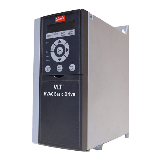
Selection ® HVAC Basic Drive FC 101 Design Guide 3 Selection Step 2 Place LCP on panel, see dimensions of hole on 3.1 Options and Accessories Illustration 3.2. 3.1.1 Local Control Panel (LCP) 62.5 + _ 0.2 Ordering no. Description... -
Page 44: Ip21/Type 1 Enclosure Kit
Selection ® HVAC Basic Drive FC 101 Design Guide 3.1.3 IP21/TYPE 1 Enclosure Kit Step 4 Connect cable to frequency converter. IP21/TYPE 1 is an optional enclosure element available for IP20 units. If the enclosure kit is used, an IP20 unit is upgraded to comply with enclosure IP21/TYPE 1. -
Page 45: Decoupling Plate
Selection ® HVAC Basic Drive FC 101 Design Guide Frame IP class Power Height Width Depth [mm] IP21 kit Type 1 kit [mm] A [mm] B ordering ordering no. 3 x 200-240 V 3 x 380-480 V 3 x 525-600 V IP20 0.25-1.5 kW... -
Page 46: How To Order
How to Order ® HVAC Basic Drive FC 101 Design Guide 4 How to Order 4.1 Configuration 4.1.1 Drive Configurator It is possible to design a frequency converter according to the application requirements by using the ordering number system. Frequency converters can be ordered as standard or with internal options by using a type code string, i.e. -
Page 47: Ordering Numbers
How to Order ® HVAC Basic Drive FC 101 Design Guide 4.1.2 Type Code String 10 11 12 13 14 15 16 17 18 19 20 28 29 38 39 Illustration 4.1 Type Code Description Pos. Possible choice Product group & FC series... - Page 48 How to Order ® HVAC Basic Drive FC 101 Design Guide 4.2.1 Ordering Numbers: Options and Accessories MG18C502 - Rev. 2013-09-06...
- Page 49 How to Order ® HVAC Basic Drive FC 101 Design Guide 4.2.2 Harmonic Filters 3x380-480 V 50 Hz 3x440-480 V 60 Hz Power Drive input Default THID Order Code Power Drive input Default THID Order Code [kW] current switching level...
- Page 50 How to Order ® HVAC Basic Drive FC 101 Design Guide 4.2.3 External RFI Filter External filters to fulfil A1 50 m/B1 20 m. Power [kW] Type L1 Torque [Nm] Weight [kg] Ordering Number Size 380-480 V 0.37-2.2 FN3258-7-45 190 40 70 160 180 20 4.5 1 10.6 M5 0.7-0.8...
-
Page 51: How To Install
How to Install ® HVAC Basic Drive FC 101 Design Guide 5 How to Install 5.1 Mechanical Dimensions 5.1.1 Frequency Converter Dimensions Enclosure Power [kW] Height [mm] Width [mm] Depth Mounting hole Max. [mm] [mm] Weight Frame 3x200-240 3x380-480 3x525-600 V... - Page 52 How to Install ® HVAC Basic Drive FC 101 Design Guide The dimensions are only for the physical units, but when installing in an application it is necessary to add space for free air passage both above and below the units. The amount of space for free air passage is listed in Table 5.2:...
-
Page 53: Shipping Dimensions
How to Install ® HVAC Basic Drive FC 101 Design Guide 5.1.2 Shipping Dimensions MG18C502 - Rev. 2013-09-06... -
Page 54: Side-By-Side Installation
How to Install ® HVAC Basic Drive FC 101 Design Guide 5.1.3 Side-by-Side Installation The frequency converter can be mounted side-by-side and requires the clearance above and below for cooling. Power [kW] Clearance above/below [mm/inch] Frame IP class 3x200-240 V... -
Page 55: Electrical Data
How to Install ® HVAC Basic Drive FC 101 Design Guide 5.2 Electrical Data 3 Phase power input Motor UDC- Not present on all power sizes UDC+ 50 (+10 V OUT) relay2 +10 V DC 0-10 V DC- 240 V AC 3 A... -
Page 56: Electrical Installation In General
How to Install ® HVAC Basic Drive FC 101 Design Guide 5.2.1 Electrical Installation in General All cabling must comply with national and local regulations on cable cross-sections and ambient temperature. Copper conductors required, (75 °C) recommended. Power [kW] Torque [Nm]... -
Page 57: Connecting To Mains And Motor
How to Install ® HVAC Basic Drive FC 101 Design Guide 5.2.2 Connecting to Mains and Motor The frequency converter is designed to operate all standard 3-phased asynchronous motors. For maximum cross-section on wires see 8.2 General Specifications. • Use a shielded/armored motor cable to comply... - Page 58 How to Install ® HVAC Basic Drive FC 101 Design Guide Illustration 5.3 H6 Frame IP20 380-480 V 30-45 kW Illustration 5.4 H7 Frame IP20 200-240 V 15-18.5 kW IP20 380-480 V 55-75 kW IP20 525-600 V 22-30 kW IP20 200-240 V 22- 30 kW...
- Page 59 How to Install ® HVAC Basic Drive FC 101 Design Guide Illustration 5.5 H8 Frame IP20 380-480 V 90 kW IP20 200-240 V 37-45 kW IP20 525-600 V 75-90 kW 1 Line 2 Relays 3 Earth 4 Motor Illustration 5.7 Mount the 2 screws in the mounting plate, slide it into place and tighten fully Table 5.11 Legend to...
- Page 60 How to Install ® HVAC Basic Drive FC 101 Design Guide Illustration 5.9 Mount mains plug and tighten wires Illustration 5.11 H10 Frame IP20 600 V 11-15 kW Illustration 5.10 Tighten support bracket on mains wires MG18C502 - Rev. 2013-09-06...
- Page 61 How to Install ® HVAC Basic Drive FC 101 Design Guide Illustration 5.13 I3 Frame IP54 380-480 V 5.5-7.5 kW 1 RS-485 Illustration 5.12 I2 Frame 2 Line in IP54 380-480 V 0.75-4.0 kW 3 Earth 4 Wire clamps 5 Motor...
- Page 62 How to Install ® HVAC Basic Drive FC 101 Design Guide Illustration 5.16 I6 Frame Illustration 5.14 I4 Frame IP54 380-480 V 22-37 kW IP54 380-480 V 0.75-4.0 kW 1 RS-485 2 Line in 3 Earth 4 Wire clamps 5 Motor...
- Page 63 How to Install ® HVAC Basic Drive FC 101 Design Guide Illustration 5.18 I6 Frame IP54 380-480 V 22-37 kW Illustration 5.19 I7, I8 Frame IP54 380-480 V 45-55 kW IP54 380-480 V 75-90 kW MG18C502 - Rev. 2013-09-06...
-
Page 64: Fuses And Circuit Breakers
Short circuit protection Danfoss recommends using the fuses and circuit breakers listed in Table 5.15 to protect service personnel or other equipment in case of an internal failure in the unit or short-circuit on DC-link. The frequency converter provides full short circuit protection in case of a short-circuit on the motor. - Page 65 How to Install ® HVAC Basic Drive FC 101 Design Guide Circuit Breaker Fuse Non UL Non UL Bussmann Bussmann Bussmann Bussmann Max fuse Power [kW] Type RK5 Type RK1 Type J Type T Type G 3x380-480 V IP20 0.37...
- Page 66 How to Install ® HVAC Basic Drive FC 101 Design Guide Circuit Breaker Fuse Non UL Non UL Bussmann Bussmann Bussmann Bussmann Max fuse Power [kW] Type RK5 Type RK1 Type J Type T Type G 3x380-480 V IP54 0.75...
- Page 67 How to Install ® HVAC Basic Drive FC 101 Design Guide 5.2.4 EMC Compliant Electrical Installation General points to be observed to ensure EMC-correct electrical installation. • Use only screened/armoured motor cables and screened/armoured control cables. • Connect the screen to earth at both ends.
- Page 68 How to Install ® HVAC Basic Drive FC 101 Design Guide Panel PLC etc. Status Quick Main Menu Menu Menu Com. Warn. Alarm Auto Hand Reset Output con- tactor etc. Earthing rail Cable insula- tion stripped Min. 16 mm Equalizing cable...
-
Page 69: Control Terminals
How to Install ® HVAC Basic Drive FC 101 Design Guide 5.2.5 Control Terminals IP20 200-240 V 0.25-11 kW and IP20 380-480 V 0.37-22 kW: Illustration 5.21 Location of Control Terminals Place a screwdriver behind the terminal cover to Illustration 5.23 IP54 400 V 0.75-7.5 kW activate snap. -
Page 70: How To Programme
How to Programme ® HVAC Basic Drive FC 101 Design Guide 6 How to Programme Parameter number and name. Parameter value. 6.1 Programming with MCT 10 Set-up Set-up number shows the active set-up and the edit set- Software up. If the same set-up acts as both active and edit set-up, only that set-up number is shown (factory setting). -
Page 71: Menus
How to Programme ® HVAC Basic Drive FC 101 Design Guide 6.3.3 Start-up Wizard for Open Loop Applications 6.3 Menus 6.3.1 Status Menu The built-in wizard menu guides the installer through the set-up of the frequency converter to an open loop application. - Page 72 How to Programme ® HVAC Basic Drive FC 101 Design Guide ... the HVAC FC 101 Wizard starts Select Regional Settings At power up the user is Power kW/50 Hz asked to choose the Setup 1 prefered laguage. Grid Type...
- Page 73 How to Programme ® HVAC Basic Drive FC 101 Design Guide Start-up Wizard for Open Loop Applications Parameter Range Default Function 0-03 Regional Settings [0] International [1] US 0-06 GridType [0] 200-240 V/50 Hz/IT-grid Size related Select operating mode for restart upon...
- Page 74 How to Programme ® HVAC Basic Drive FC 101 Design Guide Parameter Range Default Function 1-24 Motor Current 0.01-10000.00 A Size related Enter motor current from nameplate data 1-25 Motor Nominal 100.0-9999.0 RPM Size related Enter motor nominal speed from nameplate data Speed 1-26 Motor Cont.
- Page 75 How to Programme ® HVAC Basic Drive FC 101 Design Guide Parameter Range Default Function 6-11 Terminal 53 High 0-10 V 10 V Enter the voltage that corresponds to the high Voltage reference value 6-12 Terminal 53 Low 0-20 mA...
- Page 76 How to Programme ® HVAC Basic Drive FC 101 Design Guide 0-03 Regional Settings Power kW/50 Hz 0-06 Grid Type 200-240V/50Hz/Delta 1-00 Con guration Mode Closed Loop 1-10 Motor Type Asynchronous PM motor Asynchronous Motor 1-20 Motor Power 1-24 Motor Current 1.10...
- Page 77 How to Programme ® HVAC Basic Drive FC 101 Design Guide Closed Loop Set-up Wizard Parameter Range Default Function 0-03 Regional Settings [0] International [1] US 0-06 GridType [0] -[[132] see start -up wizard Size selected Select operating mode for restart upon...
- Page 78 How to Programme ® HVAC Basic Drive FC 101 Design Guide Parameter Range Default Function 1-73 Flying Start [0] Disabled Select [1] Enable to enable the frequency [1] Enabled converter to catch a spinning motor. I.e. fan applications. When PM is selected, Flying Start is enabled.
- Page 79 How to Programme ® HVAC Basic Drive FC 101 Design Guide Motor Set-up The Quick Menu Motor Set-up guides through the needed motor parameters. Parameter Range Default Function 0-03 Regional Settings [0] International [1] US 0-06 GridType [0] -[132] see start -up wizard for...
-
Page 80: Main Menu
Once the set-up of a frequency converter is complete, setting's value from another different value, the parameter Danfoss recommends to store the data in the LCP or on a will NOT be listed in Changes Made. PC via MCT 10 Set-up Software tool. - Page 81 How to Programme ® HVAC Basic Drive FC 101 Design Guide Reconnect the mains supply - the frequency converter is now reset. Except the following parameters: 8-30 Protocol 8-31 Address 8-32 Baud Rate 8-33 Parity / Stop Bits 8-35 Minimum Response Delay...
-
Page 82: Installation And Set-Up
RS-485 Installation and Set... ® HVAC Basic Drive FC 101 Design Guide 7 RS-485 Installation and Set-up 7.1 RS-485 NOTICE 7.1.1 Overview Screened, twisted-pair cables are recommended to reduce noise between conductors. RS-485 is a 2-wire bus interface compatible with multi-drop... -
Page 83: Frequency Converter Parameter Settings For Modbus Communication
RS-485 communication cable must be kept away from motor and brake resistor cables. Normally, a The address range depends on the distance of 200 mm (8 inches) is sufficient, but Danfoss protocol selected in 8-30 Protocol recommends keeping the greatest possible distance between the cables. -
Page 84: Network Configuration
RS-485 Installation and Set... ® HVAC Basic Drive FC 101 Design Guide • 7.4.2 Telegram Structure Start • Stop of the frequency converter in various ways: Each telegram has the following structure: • Coast stop • Quick stop Start character (STX)=02 Hex •... -
Page 85: The Data Field
RS-485 Installation and Set... ® HVAC Basic Drive FC 101 Design Guide 7.4.6 The Data Field The structure of data blocks depends on the type of telegram. There are 3 telegram types, and the type applies for both control telegrams (master⇒follower) and response telegrams (follower⇒master). -
Page 86: The Pke Field
RS-485 Installation and Set... ® HVAC Basic Drive FC 101 Design Guide 7.4.7 The PKE Field If the command cannot be performed, the follower sends this response: 0111 Command cannot be performed The PKE field contains 2 subfields: Parameter command... -
Page 87: Data Types Supported By The Frequency Converter
RS-485 Installation and Set... ® HVAC Basic Drive FC 101 Design Guide write the new value in the PWE block and send from the Conversion index Conversion factor master to the follower. When a follower responds to a parameter request (read command), the present parameter value in the PWE block is transferred and returned to the master. -
Page 88: Modbus Rtu Overview
RS-485 Installation and Set... ® HVAC Basic Drive FC 101 Design Guide NOTICE 7.6.2 What the User Should Already Know 4-14 Motor Speed High Limit [Hz] is a single word, and the The Modbus RTU (Remote Terminal Unit) is designed to parameter command for write in EEPROM is “E”. -
Page 89: Frequency Converter With Modbus Rtu
RS-485 Installation and Set... ® HVAC Basic Drive FC 101 Design Guide 7.6.4 Frequency Converter with Modbus 7.8 Modbus RTU Message Framing Structure The frequency converter communicates in Modbus RTU format over the built-in RS-485 interface. Modbus RTU 7.8.1 Frequency Converter with Modbus provides access to the control word and bus reference of the frequency converter. -
Page 90: Start/Stop Field
RS-485 Installation and Set... ® HVAC Basic Drive FC 101 Design Guide 7.8.3 Start/Stop Field 7.8.6 Data Field Messages start with a silent period of at least 3.5 character The data field is constructed using sets of 2 hexadecimal intervals. This is implemented as a multiple of character digits, in the range of 00 to FF hexadecimal. - Page 91 RS-485 Installation and Set... ® HVAC Basic Drive FC 101 Design Guide Coil Description Signal Coil Number Direction Control not ready Control ready 1-16 Frequency converter control word Master to Frequency converter not Frequency converter ready (see Table 7.16) follower...
-
Page 92: How To Control The Frequency Converter
RS-485 Installation and Set... ® HVAC Basic Drive FC 101 Design Guide Bus adress Bus register PLC Register Content Access Description 40001 Reserved Reserved for Legacy Drives VLT 5000 and VLT 2800 40002 Reserved Reserved for Legacy Drives VLT 5000 and VLT 2800... -
Page 93: Modbus Exception Codes
RS-485 Installation and Set... ® HVAC Basic Drive FC 101 Design Guide 7.8.11 Modbus Exception Codes Reading 3-14 Preset Relative Reference (32bit): The holding registers 3410 & 3411 holds the parameters value. A value of 11300 (Decimal), means that the parameter is set to 1113.00 S. -
Page 94: Examples
RS-485 Installation and Set... ® HVAC Basic Drive FC 101 Design Guide Non standard data types Field Name Example (HEX) Non standard data types are text strings and are stored as Follower Address 01 (frequency converter address) 4x registers (40001–4FFFF). The parameters are read using... -
Page 95: Force/Write Multiple Coils (0F Hex)
RS-485 Installation and Set... ® HVAC Basic Drive FC 101 Design Guide 7.10.3 Force/Write Multiple Coils (0F HEX) Field Name Example (HEX) Follower Address Description Function 03 (read holding registers) This function forces each coil in a sequence of coils to... -
Page 96: Preset Multiple Registers (10 Hex)
RS-485 Installation and Set... ® HVAC Basic Drive FC 101 Design Guide Response Response The normal response is an echo of the query, returned The normal response returns the follower address, function after the register contents have been passed. code, starting address, and quantity of registers preset. - Page 97 RS-485 Installation and Set... ® HVAC Basic Drive FC 101 Design Guide Make a selection in 8-53 Start Select to define how Bit 06 Programmed Parameter Ramp stop/start gates with the corresponding function on ref. value a digital input. 3-10 Preset Reference [0]...
-
Page 98: Status Word According To Fc Profile (Stw) (8-30 Protocol = Fc Profile)
RS-485 Installation and Set... ® HVAC Basic Drive FC 101 Design Guide 7.11.2 Status Word According to FC Profile Bit 04, No error/error (no trip) (STW) (8-30 Protocol = FC profile) Bit 04=’0’: The frequency converter is not in fault mode. Bit 04=“1”: The frequency converter shows an error but does... -
Page 99: Bus Speed Reference Value
RS-485 Installation and Set... ® HVAC Basic Drive FC 101 Design Guide Bit 15, Timer OK/limit exceeded Bit 15=’0’: The timers for motor thermal protection and thermal protection are not exceeded 100%. Bit 15=’1’: One of the timers exceeds 100%. -
Page 100: General Specifications And Troubleshooting
General Specifications and ... ® HVAC Basic Drive FC 101 Design Guide 8 General Specifications and Troubleshooting 8.1 Mains Supply Specifications 8.1.1 Mains Supply 3x200-240 V AC Frequency converter PK25 PK3 PK75 P1K P2K2 P3K7 P5K5 P7K5 P11K P15K P18K... -
Page 101: Mains Supply 3X380-480 V Ac
General Specifications and ... ® HVAC Basic Drive FC 101 Design Guide 8.1.2 Mains Supply 3x380-480 V AC Frequency converter PK37 PK75 P1K5 P2K2 P3K0 P4K0 P5K5 P7K5 P11K P15K Typical shaft output [kW] 0.37 0.75 11.0 15.0 Typical shaft output [hp] 10.0... - Page 102 General Specifications and ... ® HVAC Basic Drive FC 101 Design Guide Frequency converter P18K P22K P30K P37K P45K P55K P75K P90K Typical shaft output [kW] 18.5 22.0 30.0 37.0 45.0 55.0 75.0 90.0 Typical shaft output [hp] 25.0 30.0 40.0...
- Page 103 General Specifications and ... ® HVAC Basic Drive FC 101 Design Guide Frequency converter PK75 P1K5 P2K2 P3K0 P4KO P5K5 P7K5 P11K P15K P18K Typical shaft output [kW] 0.75 18.5 Typical shaft output [hp] 10.0 IP54 frame Max. cable size in terminals (mains, motor)
- Page 104 General Specifications and ... ® HVAC Basic Drive FC 101 Design Guide Frequency converter P22K P30K P37K P45K P55K P75K P90K Typical shaft output [kW] 22.0 30.0 37.0 45.0 55.0 75.0 90.0 Typical shaft output [hp] 30.0 40.0 50.0 60.0 70.0...
-
Page 105: Mains Supply 3X380-480 V Ac
General Specifications and ... ® HVAC Basic Drive FC 101 Design Guide 8.1.3 Mains Supply 3x380-480 V AC Frequency converter PK75 P1K5 P2K2 P3K0 P4KO P5K5 P7K5 P11K P15K Typical shaft output [kW] 0.75 Typical shaft output [hp] 10.0 IP54 frame... - Page 106 General Specifications and ... ® HVAC Basic Drive FC 101 Design Guide Frequency converter P18K P22K P30K P37K P45K P55K P75K P90K Typical shaft output [kW] 18.5 22.0 30.0 37.0 45.0 55.0 75.0 90.0 Typical shaft output [hp] 30.0 40.0 50.0...
-
Page 107: Mains Supply 3X525-600 V Ac
General Specifications and ... ® HVAC Basic Drive FC 101 Design Guide 8.1.4 Mains Supply 3x525-600 V AC Frequency converter P2K2 P3K0 P3K7 P5K5 P7K5 P11K P15K P18K P22K P30K P37K P45K P55K P75K P90K Typical shaft output [kW] 11.0 15.0... -
Page 108: General Specifications
General Specifications and ... ® HVAC Basic Drive FC 101 Design Guide 8.2 General Specifications Protection and features • Electronic thermal motor protection against overload. • Temperature monitoring of the heat sink ensures that the frequency converter trips in case of overtemperature •... - Page 109 General Specifications and ... ® HVAC Basic Drive FC 101 Design Guide Fault: >2.9 kΩ and no fault: <800 Ω Digital input 29 as thermistor input Digital input 29 as Pulse input Max frequency 32 kHz Push-Pull-Driven & 5 kHz (O.C.)
- Page 110 General Specifications and ... ® HVAC Basic Drive FC 101 Design Guide Control card, 10 V DC output Terminal number 10.5 V ±0.5 V Output voltage Max. load 25 mA All inputs, outputs, circuits, DC supplies and relay contacts are galvanically isolated from the supply voltage (PELV) and other high-voltage terminals.
-
Page 111: Acoustic Noise Or Vibration
General Specifications and ... ® HVAC Basic Drive FC 101 Design Guide 8.3 Acoustic Noise or Vibration If the motor or the equipment driven by the motor - e.g. a fan blade - is making noise or vibrations at certain frequencies, try the following: •... -
Page 112: Du/Dt
General Specifications and ... ® HVAC Basic Drive FC 101 Design Guide 8.4 dU/Dt Cable length [m] AC line voltage [V] Rise time [usec] [kV] dU/dt [kV/usec] peak 0,121 0,498 3.256 200 V 0.25 kW 0,182 0,615 2,706 0,258 0,540 1.666... - Page 113 General Specifications and ... ® HVAC Basic Drive FC 101 Design Guide Cable length [m] AC line voltage [V] Rise time [usec] [kV] dU/dt [kV/usec] peak 0,116 0,69 4871 400 V 11 kW 0,204 0,985 3799 0,316 1,01 2563 0,139...
-
Page 114: Derating According To Ambient Temperature And Switching Frequency
General Specifications and ... ® HVAC Basic Drive FC 101 Design Guide Cable length [m] AC line voltage [V] Rise time [usec] [kV] dU/dt [kV/usec] peak 0,192 0,972 4,083 0,356 1,32 2,949 600 V 7.5 kW 0,184 1,06 4,609 0,42... - Page 115 General Specifications and ... ® HVAC Basic Drive FC 101 Design Guide 110 % 110% 100% 100% [kHz] [kHz] Illustration 8.6 400 V IP20 H3 5.5-7.5 kW Illustration 8.9 200 V IP20 H5 11 kW 110% 110% 100% 100% [kHz] [kHz] Illustration 8.7 200 V IP20 H4 5.5-7.5 kW...
- Page 116 General Specifications and ... ® HVAC Basic Drive FC 101 Design Guide 110% 110% 100% 100% [ kHz ] [kHz] Illustration 8.12 400 V IP20 H6 30-37 kW Illustration 8.15 200 V IP20 H7 22-30 kW 110% 110% 100% 100%...
- Page 117 General Specifications and ... ® HVAC Basic Drive FC 101 Design Guide 110% 110% 100% 100% [kHz] [kHz] Illustration 8.18 200 V IP20 H8 37-45 kW Illustration 8.21 600 V IP20 H9 2.2-3 kW 110% 110 % 100% 100 %...
- Page 118 General Specifications and ... ® HVAC Basic Drive FC 101 Design Guide 110% 100% 110% 100% 45°C 50°C 55°C (kHz) [kHz] Illustration 8.27 400 V IP54 I5 11-18.5 kW Illustration 8.24 400 V IP54 I2 0.75-4.0 kW 110% 100% 110%...
- Page 119 General Specifications and ... ® HVAC Basic Drive FC 101 Design Guide 110% 100% [kHz] Illustration 8.30 400 V IP54 I7 45-55 kW 110% 100% [kHz] Illustration 8.31 400 V IP54 I8 75-90 kW MG18C502 - Rev. 2013-09-06...
-
Page 120: Index
® Index HVAC Basic Drive FC 101 Design Guide Index Dampers....................18 DANGEROUS VOLTAGE............... 9 Abbreviations..................5 Data Types Supported by the Frequency Converter... 85 Acoustic Noise..................109 DC brake....................95 Advanced Vector Control..............6 Decoupling Plate................. 43 Aggressive Environments..............11 Definitions.................... - Page 121 ® Index HVAC Basic Drive FC 101 Design Guide Menu Key....................68 Menus....................... 69 Galvanic Isolation................37 Modbus Communication................81 General Exception Codes................91 Aspects of Harmonics Emission..........35 RTU......................87 Specifications.................. 106 RTU Overview..................86 Moment of inertia................38...
- Page 122 ® Index HVAC Basic Drive FC 101 Design Guide Rated motor speed................6 Variable Air Volume..................18 RCD....................... 6, 38 control of flow and pressure............14 Read Holding Registers (03 HEX)..........93 Varying Flow over 1 Year..............14 Read-out and Programming of Indexed Parameters..78 VAV......................
- Page 123 ® Index HVAC Basic Drive FC 101 Design Guide MG18C502 - Rev. 2013-09-06...
- Page 124 130R0222 MG18C502 Rev. 2013-09-05 *MG18C502*...
Need help?
Do you have a question about the FC 101 and is the answer not in the manual?
Questions and answers