Table of Contents
Advertisement
Quick Links
Advertisement
Table of Contents

Related Manuals for Toshiba t1000


Summary of Contents for Toshiba t1000
- Page 1 UNINTERRUPTIBLE POWER SYSTEM (UPS) T1000 Series UPS INSTALLATION AND OPERATION MANUAL SINGLE PHASE - 6 KVA Rackmount Tower Configuration Configuration Part # 91074-002 July 2015 Manufactured in the USA © Copyright 2015 TOSHIBA International Corporation All rights reserved.
- Page 2 T1000 Series UPS Installation and Operation Manual – 91074-002...
-
Page 3: Qualified Personnel Only
Corporation/Social Infrastructure Systems Group/Power Electronics Division/UPS Business Unit, hereafter referred to as Toshiba UPS. The warranty contained in the contract between the parties is the sole warranty of Toshiba UPS and any statements contained herein DO NOT create new warranties or modify the existing warranty. - Page 4 Unless otherwise specified, the warranty period for a UPS battery is 24 months from the shipment date (see Toshiba International Corporation bill of lading). JOB NUMBER MODEL NUMBER SERIAL NUMBER APPLICATION SHIPMENT DATE INSTALLATION DATE INSPECTED BY T1000 Series UPS Installation and Operation Manual – 91074-002...
- Page 5 Toshiba International Corporation reserves the right, without prior notice, to update information, make product changes, or discontinue any product or service identified in this publication. Toshiba is a registered trademark of the Toshiba Corporation. All other product or trade references appearing in this manual are registered trademarks of their respective owners.
- Page 6 This page intentionally left blank. T1000 Series UPS Installation and Operation Manual – 91074-002...
-
Page 7: Table Of Contents
9.4 LCD Display - Menu/Sub-Menu Navigation ........24 9.5 LCD Display - Sub-Menu/Parameter Navigation ......25 10. UPS Operation ...................26 10.1 Initial Startup .................26 10.2 Startup (Normal) ................27 10.3 Bypass ..................27 10.4 Shutdown ..................28 T1000 Series UPS Installation and Operation Manual – 91074-002... - Page 8 16.4 System Warning Messages ............50 16.5 System Mode Messages ..............52 16.6 System Status Messages ...............53 17. Preventive Maintenance/Parts Replacement ..........54 17.1 Preventive Maintenance ..............54 17.2 LCD Display Cleaning..............54 17.3 Battery Replacement ..............54 T1000 Series UPS Installation and Operation Manual – 91074-002...
- Page 9 E.1 Optional 3-Module Tower Cap Kit - 93178 ........E-1 E.2 Optional Tower Caster Kit - 90508 ...........E-2 E.3 Optional T1000 2-Post Rack Fixed Installation Kit - 92801 ....E-5 E.4 Optional T1000 4-Post Rack Slide Installation Kit - 92800 ....E-8 E.5 Optional T1000 2-Post Rack Slide Installation Kit - 90400 ....E-11 Index ........................I-1...
- Page 10 This page intentionally left blank. T1000 Series UPS Installation and Operation Manual – 91074-002...
-
Page 11: General Safety Instructions
Electrical – Voltage & Shock Hazard Symbol indicates parts inside may cause electric shock. Explosion Hazard Symbol indicates parts may explode. Heavy Lift Hazard Symbol indicates object requires two- or more man lift, or lifting aid. T1000 Series UPS Installation and Operation Manual – 91074-002... -
Page 12: Signal Words
Notice: The FCC regulations provide that changes or modifications made to this device that are not approved by Toshiba International Corporation may void the authority granted to the user by the FCC to operate this equipment. EMC Directive Class A Note This UPS is commercial in design and not intended for use at anytime in a Residential Environment. -
Page 13: Equipment Warning Labels
TO OTHERS UNLESS PRIOR WRITTEN AUTHORIZATION IS OBTAINED. DRAWING NO.: DRAWIN 48082 T1000 Series UPS Installation and Operation Manual – 91074-002 DATE 13131 WEST LITTLE YORK ROAD, HOUSTON, TX 77041 U.S.A. 13131 WEST LITTLE YORK ROAD, HOUSTON, TX 77041 U.S.A. - Page 14 WLM 11-13 CAUTION LABEL JEE 10-14-13 WLM 4-07-14 WLM 04-14 T1000 Series UPS Installation and Operation Manual – 91074-002 THIS MATERIAL IS THE EXCLUSIVE PROPERTY OF TOSHIBA INTERNATIONAL THIS MATERIAL IS THE EXCLUSIVE PROPERTY OF TOSHIBA INTERNATIONAL PLP-FRENCH CORPORATION AND SHALL NOT BE REPRODUCED, USED, OR DISCLOSED...
-
Page 15: Important Safety Instructions
This manual contains important instructions that should be followed during the installation and maintenance of the UPS and its batteries. The T1000 Series UPS is a modular single-phase double conversion system. Each of the rackmount modules is 3U (Three Standard Rack Units) high. -
Page 16: Qualified Personnel Only
WARNING Contact with any part of a grounded battery can result in electrical shock. The likelihood of shock will be reduced if such grounds are removed prior to installation or maintenance. T1000 Series UPS Installation and Operation Manual – 91074-002... -
Page 17: Inspection/Storage/Disposal
It is illegal to dump lead-acid batteries in landfills or dispose of improperly. Please help our Earth by contacting the environmental protection agencies in your area, the battery manufacturer, or call Toshiba toll-free at (877) 867-8773 for more information about recycling. T1000 Series UPS Installation and Operation Manual – 91074-002... -
Page 18: Installation Precautions
Be approved for use as a disconnect for the country in which this equipment is installed. Be provided with a Lock Out Tag Out capability in the Off (Down) position. T1000 Series UPS Installation and Operation Manual – 91074-002... -
Page 19: Conductor Routing And Grounding
The user should provide output over-current protection for hardwired UPS systems. See “Appendix A: T1000 Specifications” on page A-1A-2 for the device rating. After ensuring that all power sources are turned off and isolated in accordance with established lockout/tagout procedures, connect the power source wiring of the correct voltage to the input terminals of the UPS. -
Page 20: Installation
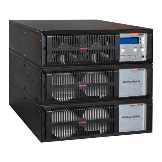
6. Installation 6.1 Module Arrangement The T1000 Series UPS consists of a Power (UPS) module, optional Battery module(s), and optional Transformer module for output other than 240/208 V. These modules can be purchased in either a rack- mount or tower configuration. -
Page 21: System Installation
6.2 System Installation The T1000 Series Power (UPS) module, optional Battery module(s), and optional Transformer module can be purchased in either a rackmount or tower configuration. All three modules are a standard 3U (3 Rack Units) tall, and fit a standard 19 in. rack. -
Page 22: Tower Installation With Cap
The Tower configuration modules are arranged side by side, and secured by a press-fit cap over the as- sembly. If the optional Caster Kit is available, see Appendix E2 for installation. 1. Unpack the T1000 modules and set them in the desired location with the faceplates at the top as shown below. -
Page 23: Rackmount Installation - Bracket Mounting Holes
Use lifting aids and proper lifting techniques when handling or installing T1000 Modules. 6.5 4-Post Rack Installation Instructions Use the 4-Post Fixed Rackmount Kit 92802 (1 kit per module) to mount the T1000 module in a 19-inch, 4-Post rack as follows. Contents - Fixed 4-Post Rack Installation Kit (92802) 1 ea.:... - Page 24 Prepare the Module(s) 4. Attach the front and rear bracket to the left and right sides of the T1000 module as shown in Fig. 6-9. Use the mounting hardware from Kit 93863 to secure the brackets to the mounting holes indicated in Fig.
- Page 25 FIGURE. 6-10: 4-POST RACK - FIXED T1000 Series UPS Installation and Operation Manual – 91074-002...
-
Page 26: Wiring The System
Block and NEMA L6-30R outlet. FIGURE 7-3: POWER MODULE WITH 6-50P LINECORD (-L1) OPTION (P/N T1P0A6000GVGL1, T1P0A6000GVGR3L1) EPO 240V Input Power Cord #10-3SO 6-50P and two each NEMA L6-30R outlets. REM. STOP T1000 Series UPS Installation and Operation Manual – 91074-002... -
Page 27: Layout - Battery Module (W/ Outlet Panel)
NEMA L6-20R, (250V 20A) L6-30R, (250V 30A) FIGURE 7-4: BATTERY MODULE OUTPUT PANEL P2 - LAYOUT 20A 30A 4.875 ASSY: 91427; PANEL: 90502 SSY: 91425; PANEL: 90500 T1000 Series UPS Installation and Operation Manual – 91074-002 10.875 10.875 0R, (125V 20A) (XFMR MODULE) BLANK PANEL... -
Page 28: Layout - Transformer Module
30 - 12 18 - 16 0.27 in 3.5 - 4.4 (0.4 - 0.5) (7 mm) Remote Switch (Plug) 30 - 12 18 - 16 3.5 - 4.4 (0.4 - 0.5) T1000 Series UPS Installation and Operation Manual – 91074-002... - Page 29 Both Factory Supplied - L6-30P twistlock to Xfmr Module keyed Module L6-30 Output to Xfmr Module Cable Anderson Connector. TB2 240V Hardwire Output User Supplied (two wire plus ground) TB1 240V Hardwire Input User Supplied (two wire plus ground) T1000 Series UPS Installation and Operation Manual – 91074-002...
- Page 30 User Selectable - Can be either a L6-30 Receptacle or a 3-Post, 3 wire terminal 240V output. Output L6-30R Receptacle Accommodates L6-30P twistlock cord (alternate output for 208/240 only). TB1 240V Hardwire Input User Supplied (two wire plus ground) T1000 Series UPS Installation and Operation Manual – 91074-002...
-
Page 31: Operating Precautions
If the UPS should emit smoke, produce an unusual odor, or make sound, turn the power off immediately. Changing/replacing the UPS Batteries should only be performed by Toshiba field service personnel. Warning signs should be placed on or near the load as a notification that the load is being powered by the UPS. -
Page 32: Control Panel
FONT: “UNINTERRUPTIBLE POWER SYSTEM”- ARIAL FONT: SMALL TEXT-ARIAL BOLD NOTE: LETTERING IS EXPLODED 9. Control Panel 4.25" 9.1 Control Panel Layout Fig. 9-1 shows the LCD display and control layout for the T1000 UPS. On-Line STATUS Input Freq: 60.0Hz Output Freq: 60.0Hz... -
Page 33: Light Emitting Diodes (Led)
When the UPS initially starts, the STATUS screen will be displayed. Use the down push button (Fig. 9-1(3)) to move the pointer down until the pointer is next to MENU. Press the Select push button (Fig. 9-1(5)). The **MENU** will open. T1000 Series UPS Installation and Operation Manual – 91074-002... -
Page 34: Lcd Display - Menu/Sub-Menu Navigation
** MENU ** Records is the last available sub-menu selection under Menu Monitor as indicated by the lack of a down arrow in the right hand column. Settings >Records FIGURE 9-2: MENU DISPLAY T1000 Series UPS Installation and Operation Manual – 91074-002... -
Page 35: Lcd Display - Sub-Menu/Parameter Navigation
(*). Success The shorthand for this operation is expressed: MENU > SETTINGS > OUTPUT > Rated Vout > Rated Vout: 200V >Rated Vout* 200V Rated Iout FIGURE 9-3: PARAMETER DISPLAY T1000 Series UPS Installation and Operation Manual – 91074-002... -
Page 36: Ups Operation
See Section 9 for control panel explanations and display navigation. Ensure no loads are connected to the UPS outlets. Apply power to the T1000 UPS System. Switch on MCCB1. The ONLINE/FAULT LED will briefly illuminate, then turn off. In Bypass, the UPS ONLINE/FAULT LED should be Off, and the AC INPUT LED a steady Green. -
Page 37: Startup (Normal)
Press and momentarily hold (~2 sec.) the RUN/STOP push button until it beeps. The ONLINE/FAULT LED will turn off. ONLINE/FAULT LED - Off AC INPUT LED - Steady Green (If the AC INPUT LED is Off, then Bypass has been disabled. See 10.3 NOTE.) T1000 Series UPS Installation and Operation Manual – 91074-002... -
Page 38: Shutdown
AC INPUT LED - Steady Green (If the AC INPUT LED is Off, then Bypass has been disabled. See 10.3 NOTE.) Remove power from the T1000 UPS System. Switch off MCCB1. The AC POWER LED will turn off. ONLINE/FAULT LED - Off... -
Page 39: System Description
This allows an orderly shutdown of critical equipment. The T1000 minimum input voltage, ViUV, is 85% of the nominal input voltage of 240V at full load. 11.3 Power Conditioning When commercial power is present, the UPS supplies conditioned power to the load while maintaining its batteries in a charged condition. -
Page 40: Operating Modes
Line Filter Inverter Power Chopper Power MOV Over- current Batteries * Switches are Protection – solid state Power Flow devices. Negative Bus FIGURE 12-2: POWER FLOW IN ONLINE MODE FOR ALL MODELS T1000 Series UPS Installation and Operation Manual – 91074-002... -
Page 41: Battery Backup (On Batteries)
Inverter Power Chopper Power MOV Over- current Batteries * Switches are Protection – solid state Power Flow devices. Negative Bus FIGURE 12-4: POWER FLOW AFTER AN EPO COMMAND FOR ALL MODELS T1000 Series UPS Installation and Operation Manual – 91074-002... -
Page 42: Cold Start (On Batteries)
NOTE: Ensure the load is disconnected before changing the CVCF parameter value. Cycle power to the UPS to save the new parameter settings. Cold Start in Frequency Conversion Mode The output frequency will be the selected output frequency CVCF Frequency. T1000 Series UPS Installation and Operation Manual – 91074-002... -
Page 43: Battery Backup Time And Discharge Process
TABLE 12-1: VOLTAGE TOLERANCES UPS Capacity 6 kVA Nominal voltage (V 216 Vdc Alarm voltage (V 194 Vdc Shutdown voltage (V 170 Vdc T1000 Series UPS Installation and Operation Manual – 91074-002... -
Page 44: Battery Recharging
The following chart shows the rated maximum and minimum battery voltages and the charge current for the UPS. TABLE 12-2: RATED BATTERY VOLTAGES Model Vmax Vmin Icharge (Float) 6 kVA 246 V 170 V 1.0 A T1000 Series UPS Installation and Operation Manual – 91074-002... -
Page 45: Battery Test
12.10 Battery Test See Fig. 9-1 for a detailed description of the LCD display layout and controls for the T1000 UPS. The T1000 allows the user to conduct automatic battery test on startup, or manual battery tests at daily, weekly, or monthly intervals. The following steps detail the battery test procedures. -
Page 46: Control Panel Menu Trees
13.1 Control Panel Navigation and Menu Access See Fig. 9.1 for a detailed description of the LCD display layout and controls for the T1000 UPS. There are four options available under the selection MENU. Only Quick Config and Settings allow the user to change parameter settings. -
Page 47: Top Menu - Sub-Menu Tree
Status Config & Ctl UPS Time Status Config & Ctl History EN Batt Test* Display & Ext Comm EN Batt Test Sup* ** RECORDS ** Fault Warning Backup Operation FIGURE 13-1: TOP MENU T1000 Series UPS Installation and Operation Manual – 91074-002... -
Page 48: Monitor Sub-Menu/Parameter Tree
Bypass Config Current State Input Current(%) Bypass Voltage EPO Status Rated InPower (W) Bypass Current Inter Comm Status Bypass Frequency Batt Test Cond Bypass Power(VA) FIGURE 13-2: MONITOR MENU AND SUB-MENUS T1000 Series UPS Installation and Operation Manual – 91074-002... -
Page 49: Setting Sub-Menu/Parameter Tree
AutoXfer Window RMTI Gateway IP Restart Mode* Batt Life Remain RMTI Status Rated Ahr RMTI Netlink No Batt (Series) No Batt (Paral) Batt Ins Date FIGURE 13.3: SETTING MENU AND SUB-MENUS T1000 Series UPS Installation and Operation Manual – 91074-002... -
Page 50: Records Sub-Menu/Parameter Tree
W3:0x0 W3:0x(Hex) OPERATION RECORD FORMAT Example: Rec No. 1139 Rec No. nn 01/12/2014 07:30:47 mm/dd/yyyy hh:mm:ss ON BATT (SEC): 19 (Message): (Duration) SOURCE: 2 SOURCE: (Source Code) FIGURE 13-5: RECORD FORMATS T1000 Series UPS Installation and Operation Manual – 91074-002... -
Page 51: Operation
Cold Start is the process of starting a UPS up in backup mode in the absence of Utility power. To cold start the T1000, perform the following steps: NOTE: If the unit is configured for frequency auto-detect (the default shipping mode), the default out- put frequency for a cold start is 60Hz. - Page 52 If the UPS is in bypass when the Remote Stop is closed, no action is taken. Detection Delay Detection Delay Closed 1-2 Sec. 1-2 Sec. Remote Status Open Switch UPS Mode Normal / Backup Mode Bypass Mode FIGURE 14-2: REMOTE STATUS SHUTDOWN TIMING T1000 Series UPS Installation and Operation Manual – 91074-002...
-
Page 53: Communication Interfaces
NO - Closed at power failure NOTE: Pin switches are shown in their inactive states. For example, if battery voltage is low, pin 7 will be connected to pin 5. FIGURE 15-1: REMOTE CONTACTS PINOUTS T1000 Series UPS Installation and Operation Manual – 91074-002... -
Page 54: Optional) Remoteye ® Network Card
15.2 (Optional) RemotEye Network Card ® The RemotEye is an optional network card for the Toshiba UPS. This card slides into a slot located on the back side (See illustration) of the UPS. The card provides a network, or LAN-based communication interface for the UPS. -
Page 55: Optional) Google Chrome
The Google Chrome browser app “Toshiba T1000 Series UPS Monitoring Program” allows any digital device running the Google Chrome browser to monitor the T1000 UPS via a cable to the USB port. The Monitoring app only allows passive monitoring of the UPS performance. -
Page 56: Optional) Emd
RJ-45 PORT FIGURE 15-4: (OPTIONAL) ENVIRONMENTAL MONITORING MODULE (EMD) - P/N RMTI-EMD-HT Smoke Detector Motion Sensor Intrusion Sensor Liquid Sensor FIGURE 15.-5: (OPTIONAL) EMD SENSORS - P/N RMTI-EMD-SENSORS T1000 Series UPS Installation and Operation Manual – 91074-002... -
Page 57: Ups Protection System
Fault relay open; Relay Contact Fault relay closed Inverter OL: Bypass relay closed Alarm Bypass relay closed Bypass OL: Bypass relay open Inverter OL: Yes if bypass is OK Auto-retransfer* Bypass OL: No T1000 Series UPS Installation and Operation Manual – 91074-002... - Page 58 Inverter OL – Transfer to bypass Audible Alarm Continuous buzzer Visible Alarm Red Fault LED on Relay Contact Fault relay closed Alarm Bypass relay closed Auto-retransfer UPS will attempt two sequential Auto-retransfers before requiring manual transfer. T1000 Series UPS Installation and Operation Manual – 91074-002...
-
Page 59: System Fault Messages
Not advisable to restart the UPS. voltage condition occurred. Call Toshiba for service. DVCOH Device Overheat – Overheating Reduce equipment load to 100% or less and try condition occurred. restarting. T1000 Series UPS Installation and Operation Manual – 91074-002... -
Page 60: System Warning Messages
Otherwise, shut down the unit and call Toshiba for service. ASYN Asynchronous mode – Input and No Action Needed. output frequency are different. Bypass is disabled. T1000 Series UPS Installation and Operation Manual – 91074-002... - Page 61 Recover without power cycle - Must Manually Disconnected Reset. • BC2 Over Temperature Reduce Load on BC, call Toshiba for Service • BC2 Lost Communications Call Toshiba for Service with UPS T1000 Series UPS Installation and Operation Manual – 91074-002...
-
Page 62: System Mode Messages
On–Line On-Line – Input converter and inverter are running (Double conversion mode). Shutdown Shutdown – No output, DC Bus is charged through Softstart Resistor. Startup Startup – UPS is starting up. T1000 Series UPS Installation and Operation Manual – 91074-002... -
Page 63: System Status Messages
TIMEDSD UPS is counting down prior to shutdown. Immediately shut down the load equipment in an orderly fashion and then press the STOP key. A warning has occurred. See Warning record. T1000 Series UPS Installation and Operation Manual – 91074-002... -
Page 64: Preventive Maintenance/Parts Replacement
The LCD display should be cleaned with a clean, damp cotton cloth to avoid scratching the coating. 17.3 Battery Replacement The T1000 comes equipped with internal backup batteries packaged in three sets of 6 batteries per bat- tery pack. NOTICE Ensure the T1000 battery packs are replaced with battery packs of the same part num- ber. -
Page 65: Shipping Weights/Dimensions
Depth Palletized Module 16.5 in. 24 in. 34 in. (491 mm) (610 mm) (864 mm) Module packaging 11 in. 23 in. 32.75 in. (without pallet) (279 mm) (584 mm) (832 mm T1000 Series UPS Installation and Operation Manual – 91074-002... - Page 66 This page intentionally left blank T1000 Series UPS Installation and Operation Manual – 91074-002...
-
Page 67: Appendix A: T1000 Specifications
4 ms (1/4 cycle) at <105% Max Load (Max load % for Retransfer) Max. Automatic Retransfer Attempts Online Transfer Time – Inverter to By- Less than 4 ms pass and Bypass to Inverter T1000 Series UPS Installation and Operation Manual – 91074-002... - Page 68 Efficiency AC-DC-AC (120V w/ 84% (Typical) Transformer Module (%) Unloaded Power Consumption 479 W Short Circuit Protection Electronic and Hardware Overload Protection Cold Start (0-100% load) Default Output Frequency 60 Hz T1000 Series UPS Installation and Operation Manual – 91074-002...
- Page 69 6 Batteries per tray, 3 trays per Battery Module Replaceable Batteries ENVIRONMENT Cooling Forced Air Operating Temperature (°F/°C) 0 - 40°C (32 - 104°F) Storage Temperature (°F/°C) -20 - 40°C (-4 - 104°F) Operating Humidity (%) 30-90% (Non-Condensing) T1000 Series UPS Installation and Operation Manual – 91074-002...
- Page 70 Standard: Terminal Block with J-Box and one (1) L6-30R receptacle Option: Mount two (2) L6-30R receptacles External Connectors EPO, USB, Remote Stop Rackmount Hardware (Standard) All Rackmount modules come standard with the 4-Post Mounting Kit, P/N 92802. T1000 Series UPS Installation and Operation Manual – 91074-002...
- Page 71 1262 1550 2065 2753 1. Typical efficiency values. Individual results may vary. T1000 BATTERY MODULE TYPICAL BACKUP TIME AT DIFFERENT LOADS Estimated* Backup time in minutes at % full load @ 0.9 PF # of T1B-6000xxx 100% 1 Battery Module >60...
- Page 72 Enclosure Enclosure of unit made from sheet metal, meets NEMA 1 and UL Type 1 Standard Construction Unit enclosure made from sheet metal meeting NEMA 1 and UL Type 1 Standard T1000 Series UPS Installation and Operation Manual – 91074-002...
- Page 73 Enclosure Enclosure of unit made from sheet metal, meets NEMA 1 and UL Type 1 Standard Construction Unit enclosure made from sheet metal meeting NEMA 1 and UL Type 1 Standard T1000 Series UPS Installation and Operation Manual – 91074-002...
- Page 74 T1000 Series UPS Installation and Operation Manual – 91074-002...
- Page 75 T1000 Series UPS Installation and Operation Manual – 91074-002...
- Page 76 T1000 Series UPS Installation and Operation Manual – 91074-002...
- Page 77 T1000 Series UPS Installation and Operation Manual – 91074-002...
- Page 78 T1000 Series UPS Installation and Operation Manual – 91074-002...
- Page 79 T1000 Series UPS Installation and Operation Manual – 91074-002...
- Page 80 T1000 Series UPS Installation and Operation Manual – 91074-002...
- Page 81 T1000 Series UPS Installation and Operation Manual – 91074-002...
- Page 82 T1000 Series UPS Installation and Operation Manual – 91074-002...
- Page 83 T1000 Series UPS Installation and Operation Manual – 91074-002...
- Page 84 T1000 Series UPS Installation and Operation Manual – 91074-002...
- Page 85 T1000 Series UPS Installation and Operation Manual – 91074-002...
- Page 86 T1000 Series UPS Installation and Operation Manual – 91074-002...
- Page 87 T1000 Series UPS Installation and Operation Manual – 91074-002...
- Page 88 T1000 Series UPS Installation and Operation Manual – 91074-002...
- Page 89 T1000 Series UPS Installation and Operation Manual – 91074-002...
- Page 90 C-10 T1000 Series UPS Installation and Operation Manual – 91074-002...
- Page 91 C-11 T1000 Series UPS Installation and Operation Manual – 91074-002...
- Page 92 C-12 T1000 Series UPS Installation and Operation Manual – 91074-002...
-
Page 93: Appendix D: T1000 Packing Lists And Kit Contents
Appendix D: T1000 Packing Lists and Kit Contents The T1000 can be ordered in many different configurations. Use the Part Number on your unit(s) to check against the packing lists below. Notify your vendor immediately of any variances. TABLE D-1: T1000 PACKAGE CONTENTS... - Page 94 T1000 Series UPS Installation and Operation Manual – 91074-002...
-
Page 95: Appendix E: T1000 Optional Installation Kit Instructions
3. Locate the front of the Tower Cap. The front of the Cap has three tabs extending beyond the skirt line. See Figure 1. 4. Fit the Tower Cap over the T1000 Modules, beginning with the front and lower the bak end over the top back of the modules. -
Page 96: Optional Tower Caster Kit - 90508
7 ea.: Screw PHP (Pan Head Phillips) 10-32 x 1/2 3. Caster Kit Installation Unpack the T1000 modules and assemble and install the casters as follows. CASTER ASSEMBLY 1. Insert each caster appliance’s threaded shafts through the Caster Bracket. (Figure 1) 2. - Page 97 8. Facing the front of the modules, arrange the modules left to right in the following order: • Transformer Module (if available) • Power Module • Battery Module with output panel(if available) • Second Battery Module without output panel (if available) T1000 Series UPS Installation and Operation Manual – 91074-002...
- Page 98 3-4 module tower systems, see T1000 Tower Cap Installation Instructions - 94037. 2. Use the leveling feet to remove weight from the casters. (Figure 5) The T1000 tower is ready for installing the interconnecting cables. See the T1000 Installation and Operation Manual - 91074.
-
Page 99: Optional T1000 2-Post Rack Fixed Installation Kit - 92801
T1000 Series UPS 2-Post Rack Fixed Kit Installation Instructions - 94035-000 1. Rackmount Fixed Installation - 2-Post Use the 2-Post Fixed Rackmount Kit 92801 (1 kit per module) to mount a T1000 module in a 2-Post 19 inch rack. 2. Contents - Fixed 2-Post Rack Installation Kit (92801) 1 ea.:... - Page 100 • Battery Panel w/o Output Panel (if present) 1. Follow the vertical arrangement of T1000 modules as indicated in the NOTE above. Secure the lowest module in the 2-Post rack to the bottom four brackets. (Figure 4) • Each Front Bracket: 2 x Phillips 10-32 x 1/2” in the center slots. (Figure 3) •...
- Page 101 FIGURE. 5: INSTALL FIRST FIGURE. 6: INSTALL REMAINING T1000 MODULE T1000 MODULES T1000 Series UPS Installation and Operation Manual – 91074-002...
-
Page 102: Optional T1000 4-Post Rack Slide Installation Kit - 92800
1. 4-Post Rack Slide Kit Use the 4-Post Rack Slide Kit 92800 (1 kit per module) to mount a T1000 module with slides in a 19-inch, 4-Post rack. The slide assemblies are non-handed, and are provided with a lock-open feature and a quick disconnect for the Inner Slide Member. - Page 103 (Figure 5). If using all four mounting slots, install all four cage nuts. 4. If more than one module is being installed for the T1000 system, install the next set of cage nuts from the other module’s 4-Post Slide Kit three (3) Rack Units (5 1/4”) above the first set of cage nuts (Figure 5).
- Page 104 3. Repeat steps 1-2 for the module slide rail set immediately above the bottom one. 4. Continue until all modules have been installed on their slide rails. 5. Go to T1000 Installation and Operation Manual - 91074 to continue installation and cabling of the T1000 System.
-
Page 105: Optional T1000 2-Post Rack Slide Installation Kit - 90400
1. 2-Post Rack Slide Kit Use the 2-Post Rack Slide Kit 90400 (1 kit per module) to mount a T1000 module with slides in a 19-inch, 2-Post rack. The slide assemblies are non-handed, and are provided with a lock-open feature and a quick disconnect for the Inner Slide Member. - Page 106 NOTE: If Rack Rail holes are threaded, use either the 1/4-20 or 10-32 bolts included in the Installation Kit. If Rack rails have square penetrations, follow instructions below.** NOTE: If installing more than one T1000 module, begin with the lowest module first. 1. Remove the cage nuts from the Slide kit.
- Page 107 6. If more than one module is being installed for the T1000 system, install the remaining mounting bracket kits as described in steps 1-5. 5. Attach Rail Assemblies to 2-Post Adapter Brackets 1. Orient the Outer Channel Body of the Slide Assembly so the open side is facing inwards, and the front is towards the rack front.
- Page 108 3. Repeat steps 1-2 for the module slide rail set immediately above the bottom one. 4. Continue until all modules have been installed on their slide rails. 5. Go to T1000 Installation and Operation Manual - 91074 to continue installation and cabling of the T1000 System.
-
Page 109: Index
59 Cold Start 47 humidity 7 Cold Start switch 28 Procedure 38 Common-mode noise 35 Input Frequency Communication interface 49 warning 27 Cooling fan 59 Input Voltage A-5 Inspection 7 T1000 Series UPS Installation and Operation Manual – 91074-002... - Page 110 MAIN tab 34 Shutdown voltage 39 maximum ambient operating temperature 5 Signal Function Mode RS-232C 49 AC Input 36 Signal Words 2 Size Normal input power supply 49 wire 24 Specifications A-1 T1000 Series UPS Installation and Operation Manual – 91074-002...
- Page 111 34 Discharge Process 37 UPS functional overview 35 UPS stop signal input 49 ventilation 27 Volume, Buzzer See Buzzer Volume warning labels 3 Warranty c Weights, shipping 60 Weights, UPS 60 T1000 Series UPS Installation and Operation Manual – 91074-002...
- Page 112 T1000 Series UPS Installation and Operation Manual – 91074-002...
- Page 114 SOCIAL INFRASTRUCTURE SYSTEMS GROUP POWER ELECTRONICS DIVISION 13131 West Little York Road, Houston, Texas 77041 Tel (713) 466-0277 Fax. (713) 896-5212 US (855) 803-7087 Canada (800) 872-2192 www.toshiba.com/tic/industrial/uninterruptible-power-systems Printed in the U.S.A.
Need help?
Do you have a question about the t1000 and is the answer not in the manual?
Questions and answers