Table of Contents

Related Manuals for Toshiba TPS0A0700AXA


Summary of Contents for Toshiba TPS0A0700AXA
- Page 1 UNINTERRUPTIBLE POWER SYSTEM (UPS) TPX Series INSTALLATION AND OPERATION MANUAL LINE INTERACTIVE 700VA/420W 120V UPS Document: 97673-000 Date: June 2017 © Copyright 2017 TOSHIBA International Corporation All rights reserved.
- Page 2 This Page Left Intentionally Blank...
- Page 3 PRODUCT USE AND WARRANTY RESTRICTION The Toshiba products listed in this document are intended for usage in general electronics applications (computer, personal equipment, office equipment, etc.). These Toshiba products are neither intended nor warranted for usage in equipment that requires extraordinarily high quality and/or reliability or where a malfunction or failure may cause loss of human life or bodily injury (Unintended Usage).
- Page 4 Unless otherwise specified, the warranty period for the UPS or UPS part is 36 months from the shipment date (see Toshiba International Corporation bill of lading). Unless otherwise specified, the warranty period for a UPS battery is 24 months from the shipment date (see Toshiba International Corporation bill of lading).
-
Page 5: Purpose And Scope Of Manual
Toshiba is a registered trademark of the Toshiba Corporation. All other product or trade references appearing in this manual are registered trademarks of their respective owners. - Page 6 TOSHIBA INTERNATIONAL CORPORATION CUSTOMER SUPPORT CENTER Toshiba International Corporation’s Customer Support Center can be contacted to obtain help in resolving any Uninterruptible Power System (UPS) problems that you may experience or to provide application information. Customer Support Center 8 a.m. to 5 p.m. (CST) – Monday through Friday USA Toll Free (877) 867-8773 –...
-
Page 7: Table Of Contents
TABLE OF CONTENTS GENERAL SAFETY INSTRUCTIONS ........1 SAFETY ALERT SYMBOL ............1 IMPORTANT SAFETY INSTRUCTIONS........4 INTRODUCTION ..............10 PRODUCT DESCRIPTION ............10 INSTALLATION ............... 10 PLACEMENT .................. 10 CONNECT COMPUTER INTERFACE (OPTIONAL) ...... 11 CONNECT TO UTILITY ..............11 CHARGE THE BATTERY ............... - Page 8 ALARMS .................. 17 BACKUP MODE ................17 LOW BATTERY ................17 OVERLOAD ..................17 SOFTWARE INSTALLATION AND USB PORT ...... 18 MONITORING SOFTWARE OVERVIEW ........18 INSTALLING SOFTWARE .............. 18 FEATURES FOR MONITORING SOFTWARE....... 18 HOW TO START MONITORING SOFTWARE ....... 19 TROUBLESHOOTING .............
-
Page 9: General Safety Instructions
1. GENERAL SAFETY INSTRUCTIONS DO NOT attempt to install, operate, maintain, or dispose of this equipment until this entire instruction manual has been read and all product warnings and user instructions are understood. 2. SAFETY ALERT SYMBOL The Safety Alert Symbol indicates that a potential personal injury hazard exists. The symbol is comprised of an equilateral triangle enclosing an exclamation mark. - Page 10 The word WARNING in capital letters preceded by the safety alert symbol indicates that a potentially hazardous situation exists that, if not avoided, could result in death or serious injury to personnel. WARNING The words CAUTION and ATTENTION in capital letters preceded by the safety alert symbol indicate a potentially hazardous situation exists which, if not avoided, may result in minor or moderate injury.
-
Page 11: Equipment Warning Labels
Explosion Hazard Symbol A symbol which indicates a hazard of injury from exploding parts. It is comprised of an equilateral triangle enclosing an explosion image. Equipment Warning Labels DO NOT attempt to install, operate, maintain, or dispose of this equipment until this entire instruction manual has been read and all product warnings and user instructions are understood. -
Page 12: Important Safety Instructions
3. IMPORTANT SAFETY INSTRUCTIONS SAVE THESE INSTRUCTIONS This manual contains important instructions that should be followed during the installation, maintenance, and operation of the UPS and its batteries to assure safe and proper operation. Qualified Personnel ONLY! Qualified Personnel refer to individuals that have the skills and knowledge relating to the construction, installation, operation, and maintenance of the electrical equipment and have received safety training on the hazards involved (Refer to the latest edition of NFPA 70E for additional safety requirements). - Page 13 WARNING Misuse of this equipment could result in injury and equipment damage. In no event will Toshiba Corporation be responsible or liable for either indirect or consequential damage or injury that may result from the misuse of this equipment. CAUTION Do not dispose of the batteries in a fire.
- Page 14 CAUTION Risk of electric shock – Refer to cautionary markings at top, or rear, or bottom of UPS. Risk of electric shock – Heat-sinks are live. Disconnect unit before servicing. (UPS has internal batteries): Risk of electric shock – Hazardous live parts inside this unit is energized from the battery supply even when the input AC power is disconnected.
- Page 15 Do not lay tools or metal parts on top of batteries. Disconnect charging source prior to connecting or disconnecting battery terminals. To reduce risk of electric shock, disconnect the UPS from the mains supply before installing a computer interface signal cable. Reconnect the power cord only after signaling interconnections have been made.
- Page 16 CAUTION The unit has a dangerous amount of voltage. If the UPS indicator is on, the unit’s outlets may have a dangerous amount of voltage even when not plugged into the wall outlet because the battery may continue to supply power. Ensure installation is indoors, free from electrically-conductive particles, temperature and humidity controlled in order to reduce the risk of electric shock.
- Page 17 Special Symbols The following are examples of symbols used on the UPS to alert nearby personnel to important information: RISK OF ELECTRIC SHOCK – Please observe the warning that a risk of electric shock is present. CAUTION: REFER TO OPERATOR’S MANUAL – Refer to the operator’s manual for additional information, such as important operating and maintenance instructions.
-
Page 18: Introduction
5. PRODUCT DESCRIPTION Toshiba’s TPX Series, line-interactive pure sine wave UPS system protects computers, servers, networking accessories and telecommunication equipment from blackouts, voltage fluctuations and transient surges. It includes 6 protected NEMA 5-15R output receptacles total, 3 of which offer surge suppression only for less critical desktop accessories. -
Page 19: Connect Computer Interface (Optional)
UPS. Note: The Toshiba UPS is designed to support electronic equipment only. The UPS will be overloaded if the total VA rating for all equipment connected through the battery backup/surge protection outlets exceeds the UPS's Output Capacity. -
Page 20: Front Panel View
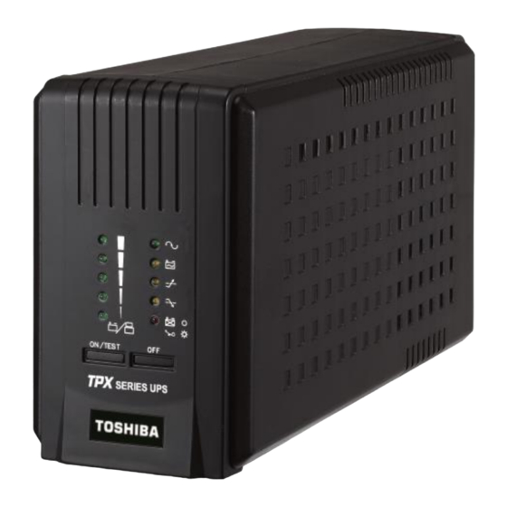
6.6 FRONT PANEL VIEW “OFF” button: Press the OFF button to turn off the UPS and the loads. “ON/TEST” button: With the UPS plugged in, press the ON/TEST button to turn on the UPS and power the loads. -
Page 21: Rear Panel View
“LINE NORMAL” indicator (GREEN LED): The LED illuminates when the utility input voltage is normal. “LOAD LEVEL / BATTERY CAPACITY” bar graph: When utility power is normal, the LED bar shows the load level. When in back up mode, it shows the battery capacity. 6.7 REAR PANEL VIEW ... - Page 22 INPUT LINE CORD/POWER CORD The input power cord needs to connect into a socket on the wall. Please notice the voltage of utility power should match with the UPS. For example, the rated voltage of the UPS is 120V so the input utility power should also be 120V. ...
-
Page 23: Operation
7. OPERATION 7.1 TURN ON While utility input is connected to the UPS, press the "ON/TEST" button for over 2 seconds to turn on the UPS. After that, connect the electrical cords of the load equipment to the outlets on the rear panel of the UPS. Do not exceed rated load of the UPS with connected equipment. -
Page 24: Load Level / Battery Capacity Bar Graph
Recharge the battery overnight and perform the self-test again. If the replace battery LED is still on, the battery will need to be replaced. 7.5 LOAD LEVEL / BATTERY CAPACITY BAR GRAPH When line voltage is normal, the 5-LED display shows the power drawn from the UPS by load. -
Page 25: Alarms
8. ALARMS 8.1 BACKUP MODE When the UPS is working under “BACKUP” mode, the UPS emits an audible alarm. The alarm stops when the UPS returns to “ONLINE” operation. The alarm can be stopped by pressing the “ON/TEST” button during backup mode. Attention: The alarm of “BACKUP”... -
Page 26: Software Installation And Usb Port
9. SOFTWARE INSTALLATION AND USB PORT 9.1 MONITORING SOFTWARE OVERVIEW The UPS comes with local monitoring software. The UPS should be connected to the computer that will be monitoring the UPS using the supplied USB cable. It can provide a graceful shutdown of the computer in the event of power failure. -
Page 27: How To Start Monitoring Software
9.4 HOW TO START MONITORING SOFTWARE After installation of the monitoring software is completed, launch the software by clicking on the icon on the system tray from the Operating System. The main menu of the monitoring software will appear. Example below: The main menu contains tools and features for monitoring UPS operation and controlling the UPS. -
Page 28: Troubleshooting
TROUBLESHOOTING PROBLEM POSSIBLE CAUSE SOLUTIONS Input power source issue Check out the power source UPS can't Keep pressing the “ON/TEST” Duration of button press too operate after short button over 2 seconds pressing “ON/TEST” Turn off UPS, take off all load to switch make sure there are no problems Output short circuit or overload... -
Page 29: Specifications
SPECIFICATIONS TPS0A0700AXA Model Number 700VA/420W Capacity Voltage 120V +/-25% of nominal at line input Input Frequency 50 or 60Hz +/-10% (auto sensing) Voltage (battery 120V +/-5% mode) Output Frequency 50 or 60Hz +/-0.5% Waveform Pure Sine Wave Surge 890 Joules, 10/1000us Fuse or Circuit breaker for overload &... - Page 30 Estimated Runtime Full Load BATT 100% 12V/9AH*1 *Runtime shown in minutes. Runtimes are approximate as battery performance is affected by many factors including age, number of discharges, depth of discharges, and ambient temperature. All rights reserved. All trademarks are property of their respective owners. Specifications subject to change without notice.
-
Page 31: Inspection/Storage/Disposal
INSPECTION/STORAGE/DISPOSAL 12.1 INSPECTION Upon receipt of the UPS, an inspection for shipping damage should be performed. Use caution when removing the unit from the box. Refer to labels or documentation attached to packing material. 12.2 UNPACKING Check the unit for loose, broken, bent or otherwise damaged parts. If damage has occurred during shipping, keep all original packing materials for return to the shipping agent. - Page 32 It is illegal to dump lead-acid batteries in landfills or dispose of improperly. Please help the environment by contacting the environmental protection agencies in your area, the battery manufacturer, or call Toshiba toll-free at (877) 867-8773 for more information about recycling.
-
Page 33: Installation Precautions
INSTALLATION PRECAUTIONS CAUTION 1. Install the unit in a well-ventilated location; allow at least 4 inches (10 cm) between the rear panel and the wall for air ventilation. 2. Install the unit in a stable, level and upright position that is free of excessive vibration. 3. -
Page 34: Operating Precautions
5. Do not insert metal objects or combustible materials in the ventilation slots of the UPS. 6. Do not place, hang, or paste any objects on the exterior surfaces of the UPS. 7. Do not attempt to disassemble, modify, or repair the UPS. Call a local Toshiba representative for repair information. -
Page 35: Maintenance
The TPX Series UPS is not designed for field-level service. All repairs will be done at the Depot-level. All Toshiba UPS Systems function with a minimal amount of maintenance. Changing the batteries at the recommended intervals will help ensure the full life of the battery and reduced chance of failure. - Page 36 WARNING! Batteries may cause electrical shock or burns from high short circuit currents. Please observe the following precautions: 1. Remove jewelry and metal objects such as watches and rings. 2. Use tools that have insulated handles. 3. Keep tools and other metal objects from contacting and away from the batteries.
-
Page 37: Replacing Batteries
15.1 REPLACING BATTERIES Before replacing batteries, ensure that the UPS has been turned off and the input power cord is unplugged. Replacing batteries (700 VA) 1) Position the unit sideways and keep it stable. 2) Remove the screw. 3) Press down the battery cover hook and push the cover upward. -
Page 38: Service And Warranty
If the unit requires service, do not return it to the dealer. Follow these steps: Review the ‘Troubleshooting’ section of the manual to resolve common problems. If the problem persists, contact Toshiba International Corporations support group for further assistance. See Contact Customer Support section for contact numbers or visit www.toshibaups.com. ... -
Page 39: Limited Warranty
16.2 LIMITED WARRANTY Toshiba International Corporation (TIC) warrants its products to be free from defects in materials and workmanship for a period of three (3) years excluding the batteries, which are warranted for two (2) years from the date of purchase. TIC’s obligation under this warranty is limited to repairing or replacing, at its own sole discretion, any such defective products. - Page 40 Replacement of defective product/unit does not include cost of removal, shipping, or any charges or cost associated with unit replacement. TIC HEREBY EXPRESSLY DISCLAIMS ALL OTHER EXPRESS, STATUTORY AND IMPLIED WARRANTIES, INCLUDING WITHOUT LIMITATION, THE IMPLIED WARRANTIES OF MERCHANTABILITY AND FITNESS FOR A PARTICULAR PURPOSE. TPX Series UPS 700VA Operational Manual –...
- Page 41 13131 West Little York Rd., Houston, TX 77041 Tel: 713/466-0277 Fax 713/466-8773 US 877/867-8773 www.toshibaups.com Printed in Taiwan...
Need help?
Do you have a question about the TPS0A0700AXA and is the answer not in the manual?
Questions and answers