Table of Contents
Advertisement
Next-Generation IGBT Technology
True On-Line, Double-Conversion UPS
Parallel up to Four Units
Input Power Factor > 0.99
Input Current THD < 3%
Output Power Factor 0.9
100% Unbalanced Load Capability
Wide Input Voltage Range +15%, -20% (Without Utilizing Batteries)
High Efficiency for Lower Operational Cost
Smallest Footprint and Highest Power Density in Industry
Electronic Battery Isolation for Battery Longevity
Generator-Friendly Design and Compatibility
Complete Front-Access for Installation, Operation, and Service
Handles Leading Power Factor Loads (Without Derating)
SNMP/Web-Based Monitoring
Three-Year Warranty for Lower Cost of Ownership
UNINTERRUPTIBLE POWER SYSTEMS
96.5%
Efficiency
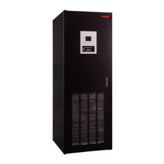
G9000 Series
Extended
80/100/160/225 KVA UPS
Extended
Extended
Warranty
Available
Extended
Available
Extended
Warranty
Available
Advertisement
Chapters
Table of Contents

Related Manuals for Toshiba T90S3S08KS6XSN


Summary of Contents for Toshiba T90S3S08KS6XSN
- Page 1 UNINTERRUPTIBLE POWER SYSTEMS G9000 Series Extended 80/100/160/225 KVA UPS 96.5% Efficiency Extended Extended Next-Generation IGBT Technology Warranty Available True On-Line, Double-Conversion UPS Parallel up to Four Units Extended Warranty Input Power Factor > 0.99 Available Input Current THD < 3% ...
- Page 2 UL 1778, CUL, ISO9001, ISO14001, ANSI C62.41 (IEEE 587), FCC Class A, Article 47, Part 15.B Warranty Three Years Onsite (Optional Two Year Extended Warranty) See Toshiba Warranty Policy for Full Details Service 24-Hour, 365-Day Technical Support 1-877-867-8773 Two G9000 UPS Modules in...
- Page 3 CORPORATE OFFICE 13131 WEST LITTLE YORK ROAD HOUSTON, TX 77041 PHONE: (713) 466-0277 (800) 231-1412 FACSIMILE: (713) 896-5226 TOSHIBA G9000 80/100/160/225 kVA GUIDE SPECIFICATION THREE PHASE UNINTERRUPTIBLE POWER SUPPLY 61963-000 March 2009...
- Page 4 Guide Specification – 3-Phase Static Uninterruptible Power Supply This Page Intentionally Left Blank March 2009...
-
Page 5: Table Of Contents
COMMUNICATIONS (OPTIONAL) ..........................15 II N ............................15 EMOT ETWORK DAPTER 9.1.1 SNMP Ability ..............................15 9.1.2 HTTP Familiarity ..............................15 9.1.3 Shutdown Capability ............................15 (RSAP)..........................16 EMOTE TATUS LARM ANEL TOSHIBA DISTRIBUTION CABINET (TDC) (OPTION) ....................16 March 2009... - Page 6 Guide Specification – 3-Phase Static Uninterruptible Power Supply MAINTENANCE BYPASS PANEL (OPTION) ........................16 11.1 ............................... 16 NSTALLATION 11.2 ............................16 LECTRICAL ONFIGURATION 11.3 .............................. 16 ECHANICAL NTERLOCK 11.4 : ..........................16 XTERNAL AINTENANCE YPASS AUXILIARY TRANSFORMER CABINETS (OPTION) ....................... 17 POWER DISTRIBUTION UNITS (OPTION) ........................
-
Page 7: Scope
** The following components shall be optional: 1. Battery Cabinet with DC Breaker 2. Toshiba Distribution Cabinet (TDC) 3. Toshiba Tie Cabinet for parallel operation 4. Maintenance Bypass Panel (Circuit Breaker) 5. RemotEye II UPS remote communications and web-based monitor card 6. -
Page 8: System Operation
Guide Specification – 3-Phase Static Uninterruptible Power Supply 2.3 System Operation: The UPS shall operate as a fully automatic on-line system in the following modes: 2.3.1 Normal IGBT Rectifier converts AC input power to DC power for the inverter and for charging the batteries. -
Page 9: Clearances For Installation
Guide Specification – 3-Phase Static Uninterruptible Power Supply 3.2.3 Clearances for installation Ceiling Level : 20” minimum from top of UPS to ceiling Front : 40” minimum for maintenance (Local and regional codes may apply) Bottom : Knockouts for power cable access Rear : Zero clearance required Sides... - Page 10 Guide Specification – 3-Phase Static Uninterruptible Power Supply Input Power Factor : Greater than 0.99 lagging at 25%-115% load Current THD : 3% maximum THD at 60%–100% load 6% maximum THD at 25%–59% load (No input harmonic filter required) 4.1.3 Charging Function: DC Nominal Voltage : 480 V AC Ripple on DC Bus...
-
Page 11: Functional Description
Guide Specification – 3-Phase Static Uninterruptible Power Supply Rated Load Power Factor : 0.9 PF lagging Overload Capacity : 125% for 2 min., 150% for 1 min. Harmonic Voltage Distortion : 2% maximum THD (100% Linear Load) : 5% maximum THD (100% Non-linear Load) Phase Displacement : 1°... -
Page 12: Igbt Inverter
Guide Specification – 3-Phase Static Uninterruptible Power Supply The Converter logic shall provide DC for controlled battery charging. The battery current sensing shall be independent of the Converter DC Output current sensing to provide precise battery recharging control. The DC/DC Charging Converter shall include a circuit to regulate the battery charging current to between 100% and 125% of maximum battery charging current.. -
Page 13: Static Bypass Circuit
Guide Specification – 3-Phase Static Uninterruptible Power Supply 5.3.4 Output Control The Inverter can be manually started and stopped using the LCD touch screen controls. 5.3.5 Overload Capacity: The Inverter output shall be capable of providing an overload current of 125% for 2 min. and 150% for 1 min. -
Page 14: Metering, Monitoring, Alarms, And Controls
Guide Specification – 3-Phase Static Uninterruptible Power Supply Transfer Type Operating Mode Transfer mode Synchronized Unsynchronized Inverter to Bypass Automatic Uninterrupted Interrupted (Overload, Internal Fault) “BYPASS” Interrupted Inverter to Bypass Uninterrupted switch operated (forced transfer) Bypass to Inverter Automatic Uninterrupted Transfer inhibited (Auto-Retransfer Mode) “UPS”... - Page 15 Guide Specification – 3-Phase Static Uninterruptible Power Supply 5.5.3 Liquid Crystal Display (LCD) Touch Panel The Front Panel shall include a LCD touch panel that shall provide performance data, statistics, and operating conditions. The following metering will be displayed on LCD touch panel: AC Input Voltage AC Input Frequency...
-
Page 16: Mechanical Design
The back-up batteries shall come with a ten-year warranty: three years full, then prorated over the remaining seven years.. Parts, labor, and travel are included during warranty period. Optional extended warranties shall be available. See Toshiba warranties at www.toshiba.com/ind 7.3 Warranty Support Availability Warranty and technical support shall be available 24/7/365. -
Page 17: Communications (Optional)
Toshiba UPS communication protocol SNMP over UDP/IP : HTTP over TCP/IP:ARP, RARP, TFTP and ICMP MIB_II : Toshiba v1.2_MIB :JEM MIB : RFC 1628 Traffic LED for network : Status LED for status : Power LED for Power 2 digit (default setting is Switches 1 and 2 off) Temperature Range: 0 –... -
Page 18: Remote Status Alarm Panel (Rsap)
Low Battery, AC Fail New alarm annunciation Battery backup for the RSAP monitor. TOSHIBA DISTRIBUTION CABINET (TDC) (OPTION) The manufacturer can optionally provide a matching TDC for the UPS. The TDC can include a step-down, 480/208/120 V transformer in a matching NEMA1 cabinet. -
Page 19: Power Distribution Units (Option)
Guide Specification – 3-Phase Static Uninterruptible Power Supply AUXILIARY TRANSFORMER CABINETS (OPTION) The UPS manufacturer can provide optional Auxiliary Transformer Cabinets (ATC) for stepping the UPS output voltage down to service load voltages. POWER DISTRIBUTION UNITS (OPTION) The UPS manufacturer shall provide optional PDUs (Power Distribution Units) for stepping the UPS output voltage down to service load voltages. - Page 20 INTERNATIONAL CORPORATION Approved by 480V Single Input, 480V Output Houston Texas, USA THIS MATERIAL IS THE EXCLUSIVE PROPERTY OF TOSHIBA INTERNATIONAL CORPORTION AND SHALL NOT DRAWING NO. REV. BE REPRODUCED, USED, OR DISCLOSED TO OTHERS T90S3S08KS6XSN UNLESS PRIOR WRITTEN AUTHORIZATION IS OBTAINED.
- Page 22 INTERNATIONAL CORPORATION Approved by 480V Single Input, 480V Output Houston Texas, USA THIS MATERIAL IS THE EXCLUSIVE PROPERTY OF TOSHIBA INTERNATIONAL CORPORTION AND SHALL NOT DRAWING NO. REV. BE REPRODUCED, USED, OR DISCLOSED TO OTHERS T90S3S10KS6XSN UNLESS PRIOR WRITTEN AUTHORIZATION IS OBTAINED.
- Page 24 INTERNATIONAL CORPORATION Approved by 480V Single Input, 480V Output Houston Texas, USA THIS MATERIAL IS THE EXCLUSIVE PROPERTY OF TOSHIBA INTERNATIONAL CORPORTION AND SHALL NOT DRAWING NO. REV. BE REPRODUCED, USED, OR DISCLOSED TO OTHERS T90S3S16KS6XSN UNLESS PRIOR WRITTEN AUTHORIZATION IS OBTAINED.
- Page 26 INTERNATIONAL CORPORATION Approved by 480V Single Input, 480V Output Houston Texas, USA THIS MATERIAL IS THE EXCLUSIVE PROPERTY OF TOSHIBA INTERNATIONAL CORPORTION AND SHALL NOT DRAWING NO. REV. BE REPRODUCED, USED, OR DISCLOSED TO OTHERS T90S3S22KS6XSN UNLESS PRIOR WRITTEN AUTHORIZATION IS OBTAINED.
- Page 28 UNINTERRUPTIBLE POWER SYSTEM (UPS) G9000 SERIES INSTALLATION AND OPERATION MANUAL 480/480 V 80/100/160/225 kVA Document: GBH0016 Rev. 0.21 P/N 61480-000 April 2009...
- Page 29 G9000 Installation and Operation Manual...
- Page 30 G9000 SERIES INSTALLATION AND OPERATION MANUAL 480/480 V 80/100/160/225 kVA Document No. GBH0016 Rev. 0.21 P/N 61480-000 April 2009 G9000 Installation and Operation Manual...
- Page 31 G9000 Installation and Operation Manual...
-
Page 32: Important Notice
The sales contract contains the entire obligation of TOSHIBA INTERNATIONAL CORPORATION. The warranty contained in the contract between the parties is the sole warranty of TOSHIBA, and any statements contained herein do not create new warranties or modify the existing warranty. -
Page 33: Purpose And Scope Of Manual
TOSHIBA shall not be liable for technical or editorial omissions or mistakes in this manual. Nor shall it be liable for incidental or consequential damages resulting from the use of information contained in this manual. - Page 34 Table of Contents List of Tables ............................ii List of Figures ............................iii How to use this Manual ........................1 INTRODUCTION ......................... 2 SAFETY PRECAUTIONS ....................... 3 GENERAL ..........................6 DEFINITIONS.......................... 7 OPERATION OVERVIEW ....................... 8 SPECIFICATIONS ........................ 15 OPERATOR CONTROLS AND INDICATORS ................. 20 LED DISPLAY ........................
-
Page 35: List Of Tables
List of Tables Table 1.1 UPS Installation Environment ................... 4 Table 1.2 Rating of Bypass Input Circuit Breaker ..............5 Table 1.3 Power Specifications ....................15 Table 1.4 UPS Module Information ..................16 Table 1.5.a Detail of Specifications ..................... 16 Table 1.5.b Efficiency at Various Loads .................. - Page 36 List of Figures Single Line Diagram – Normal Operation..............8 Figure 1.1 Single Line Diagram – Bypass Operation ..............9 Figure 1.2 Single Line Diagram – Battery Operation ..............10 Figure 1.3 Figure 1.4.1 UPS Parts Location (80,100kVA) ................12 Figure 1.4.2 UPS Parts Location (160,225kVA) ................
- Page 37 Figure 3.3 Diag. of Power wire & Control wire Inter-connect between UPS and Battery ..44 Figure 3.4 Diag. of Power wire Connect (Parallel Connection) ..........45 Figure 3.5 Diag. of Power and Control wire Connect (Parallel Connection) ......46 Figure 3.6 LCD Screen (MMS Operation) .................
-
Page 38: How To Use This Manual
Prohibit: A prohibit symbol shows the act the user or the service personnel should NEVER perform during the UPS installation, operation or service work. PROHIBIT Safety Recommendations: If any problems are encountered while following this manual, Toshiba field service group assistance and correspondence is recommended. G9000 Installation and Operation Manual... -
Page 39: Introduction
INTRODUCTION The Toshiba Uninterruptible Power Supply System (UPS) is designed to provide many years of reliable protection from power failure, brown-outs, line noise, and voltage transients. To ensure optimum performance of the equipment, follow the manufacturer's instructions. This manual contains descriptions required to operate the UPS. Please read this manual carefully and retain it for future reference. -
Page 40: Safety Precautions
WARNING 2 CAUTION In no event will TOSHIBA be responsible or liable for either indirect or consequential damage or injury that may come from the use of this equipment. Don’t modify the UPS entirely or partially. Any modifications without authorization by TOSHIBA could result in personal injuries, death or destruction of the UPS. -
Page 41: Table 1.1 Ups Installation Environment
WARNING 3 NOTE The UPS is to be installed in a controlled environment. Improper storage and installation environment may deteriorate insulation, shorten component life and cause malfunctions. Keep the installation environment per standard described as follows: TABLE 1.1 UPS Installation Environment Item Environment standard Installation... -
Page 42: Table 1.2 Rating Of Bypass Input Circuit Breaker
WARNING 4 NOTE This UPS does not include a Bypass input circuit breaker (MCCB) to protect the bypass circuit. The Bypass input circuit breaker (MCCB) is to be field supplied and installed. Recommended Breaker (MCCB)'s Specifications are as follows: TABLE 1.2 Rating of Bypass Input Circuit Breaker Capacity (kVA) Bypass Voltage (Vac) Bypass Rating (Aac) Breaker (A) -
Page 43: General
GENERAL The Toshiba G9000 UPS is designed to provide continuous and clean electrical power to a critical load. Additionally the UPS monitors power conditions affecting the load. In the event of an input power failure, the UPS will supply power to the critical load for the specified battery time. -
Page 44: Definitions
DEFINITIONS UNINTERRUPTIBLE POWER SUPPLY SYSTEM (UPS) - All components within the UPS Module Cabinet and associated batteries that function as a system to provide continuous, conditioned AC power to a load. This is sometimes referred to as the "System". UPS MODULE CABINET - The metal enclosure which contains the Converter / Charger, Inverter, Static Transfer Switch, Internal Bypass line, operator controls, and internal control systems required to provide specified AC power to a load. -
Page 45: Operation Overview
OPERATION OVERVIEW The UPS provides two power paths between the utility source and the critical load. Figure 1.1 shows the path for normal operation, with the load powered by the inverter. Figure 1.2 shows the path for bypass operation, with the load supplied through the static bypass line. -
Page 46: Figure 1.2 Single Line Diagram - Bypass Operation
In the event of a UPS module failure during Parallel Operation, the critical load power will be continually supplied and shared by all other UPS. The Bypass Input breaker and cables are to be supplied and installed by the user or the constructor. -
Page 47: Figure 1.3 Single Line Diagram - Battery Operation
In the event of a load overcurrent, the UPS transfers to bypass without interruption to the critical load. In the case of the Parallel Operation, all UPS will transfer to bypass without interruption to the critical load. The internal control system determines the operation of the two paths, with the load powered from the inverter being the normal operation. - Page 48 When power is restored after a low battery shutdown, the UPS converter(s) automatically restarts operation, the charger(s) recharges the batteries and the Inverter(s) is automatically restarted without operator intervention. Load is automatically assumed by the inverter without operator intervention. (s)* : In the case of the Parallel Operation The power drawn by the load is equally shared between all UPS regardless of the presence or absence of the UPS that is (are) in battery operation or not whenever the system is in the Parallel Operation.
-
Page 49: Figure 1.4.1 Ups Parts Location (80,100Kva)
FIGURE 1.4.1 UPS Parts Location (80,100kVA) UPS module Front View 8. Parallel I/F PCB CPMS IFAU-08 CPMC Inverter, Converter, Charger Unit 5. Relay PCB 1. LCD touch panel RYAU-09 monitor display 2. Display PCB 4. Main PCB DPAU-81 UPGR-M 6. External Communication Connector 7. -
Page 50: Figure 1.5 Display Pcb Dpau-81
FIGURE 1.5 Display PCB DPAU-81 CNV. SW. switch 13. SW6 START STOP 11. SW1 12. SW5 MAINTENANCE button button RESET switch TEST switch button FIGURE 1.6 External I/F PCB IOAU-09 External contact signal terminal block IOAU-0 FIGURE 1.7 Parallel I/F PCB IFAU-08 IFAU-0 TLIN TLOUT... -
Page 51: Figure 1.8 Main Pcb Upgr-Ma
FIGURE 1.8 MAIN PCB UPGR-MA 15. SW3 52L S/W switch UPGR-M 14. SW2 11. SW1 BOOT switch RESET switch Description of Figures 1.4 to 1.8: LCD Touch Panel Monitor Display The Liquid Crystal Display (LCD) Touch Panel Monitor Display indicates power flow, measured values and fault and error messages via user selectable display screens. -
Page 52: Specifications
- (15) SW3 (52L S/W switch) Relay PCB RYAU-09 External Communication Connector RS232C connector on DPAU-81 board : FOR SERVICE PERSONNEL ONLY Refer to FIGURE 2.18 for details. Parallel control PCB TLCR-C For use in Parallel Operation system application : Option Parallel I/F PCB IFAU-08 For use in Parallel Operation system application : Option (Figure 1.7): Refer to FIGURE 3.5 for details. -
Page 53: Table 1.4 Ups Module Information
TABLE 1.4 UPS Module Information a) Cabinet Dimension Width Depth Height Net Weight Heating Cable [kVA] [in.] [in.] [in.] [lbs.] [BTU/h] Knockout (mm) (mm) (mm) (kg) 27.6 32.8 80.6 10,771 BOTTOM (700) (832) (2,047) (388) 27.6 32.8 80.6 13,463 BOTTOM (700) (832) (2,047) - Page 54 STATIC BYPASS INPUT Configuration 3 phase, 3 wire ±10% Voltage 480 V 60 Hz ±5% Frequency Bypass Overload 1000% for 1 Cycle BATTERY Type Lead Acid Ride Through Application Specific Nominal Voltage 480 Vdc Minimum Voltage 400 Vdc Float Voltage Up to 545 Vdc DC Ripple Current 9 Adc...
-
Page 55: Table 1.5.B Efficiency At Various Loads
Operating Temperature 32 F to 104 F ( 0 C to 40 C). Recommended : 68゚F to 86゚F ( 20 C to 30 C) 5% – 95% Non Condensing Relative Humidity Altitude 0 to 7380 feet No Derating at 40゚C Location Indoor (free from corrosive gases and dust) Paint Color... - Page 56 TABLE 1.6 Rating of Contactors, Breaker and Fuses OUTPUT CAPACITY OF EQUIPMENT 80kVA 100kVA 160kVA 225kVA NUMBER APPLICATION 72kW 90kW 144kW 202.5kW AC input contactor 135A 135A 200A 285A STS contactor 135A 150A Inverter output 135A 135A 200A 285A contactor Bypass contactor 135A 135A...
-
Page 57: Operator Controls And Indicators
OPERATOR CONTROLS AND INDICATORS The G9000 Series operator controls and indicators are located as follows (Door exterior) : FIGURE 2.1 Operation/Display Panel (Front panel) G9000 Installation and Operation Manual... -
Page 58: Led Display
LED DISPLAY 1) Load on inverter [ LOAD ON INVERTER ](green) Illuminates when power is supplied from inverter to the critical load. (Indicates the state of inverter transfer switch "52C".) 2) Battery operation [ BATTERY OP. ](orange) Illuminates when power is supplied from batteries following a power failure. 3) Load on bypass [ LOAD ON BYPASS ](orange) Illuminates when power is supplied to load devices by static bypass. -
Page 59: Liquid Crystal Display (8)
LIQUID CRYSTAL DISPLAY (8) The Liquid Crystal Display (LCD) touch panel indicates power flow, measured values, operational guidance, data records and error messages. The LCD panel has a back-light which facilitates viewing in different ambient lighting conditions. The LCD will automatically clear and turn off, if the screen is not activated within 3 minute period. -
Page 60: Figure 2.3.1 Startup/Shutdown Screen
FIGURE 2.3.1 Startup/Shutdown Guidance FIGURE 2.3.2 Startup guidance FIGURE 2.3.3 Shutdown guidance Follow Startup/Shutdown guidance accordingly. MEASUREMENT MENU (FIGURE 2.4) This screen shows details of measured values. Input and Output values are displayed. During Battery operation, Remaining battery power and Run time are also displayed. FIGURE 2.4.1 Input values G9000 Installation and Operation Manual... -
Page 61: Figure 2.4.2 Output Values
FIGURE 2.4.2 Output values FIGURE 2.4.3 Values in Battery operation C) OPERATION MENU (FIGURE 2.5) This screen prompts the user to select: (a) whether the start & stop operation will be performed by local or remote operation; (b) date & time adjustment; (c) battery equalizing charge. The battery equalizing charge operation key will appear when battery equalizing charge is set up (Setup is based on battery type). -
Page 62: Figure 2.6.1 Log Menu
D) LOG MENU (FIGURE 2.6) This LOG MENU displays two Touch icons in EVENT LOG and BATTERY LOG. Pressing the EVENT LOG icon, up to 50 condition/operation records will be displayed. Press ▲ or ▼ button for page turning. Pressing the BATTERY LOG icon, Number of battery operations and Summed battery operation time are displayed. -
Page 63: Input Power Failure
2.3.2 Input Power Failure During an Input Power Failure, the UPS inverter will be powered by the UPS batteries. The following will be displayed on the main and measurement screen (Indication of battery operation and remaining battery time). FIGURE 2.7.1 Main screen FIGURE 2.7.2 Measurement screen (Battery operation) (Battery operation) -
Page 64: Figure 2.9 Message Screen
1) MESSAGE The display shows a fault code, the description of the fault and a guidance of what action is to be taken by the user. A maximum of 10 faults are displayed at one time. If an input power failure occurs during a fault condition, the fault indication and input power failure announcement are alternatively displayed at 5 second intervals. -
Page 65: External Signal Terminal Block
EXTERNAL SIGNAL TERMINAL BLOCK The UPS is equipped with a series of input/output terminals for external annunciation of alarms and for remote access of certain UPS functions. The layout of terminals is shown in Figure 2.10.1 and 2.10.2 with a functional description of the input/output port presented. OUT1 to OUT8 are user programmable, but factory default settings are shown in Figure 2.10.1. -
Page 66: Figure 2.10.2 External Signal Terminal Block (Tn1)
FIGURE 2.10.2 External Signal Terminal Block (NEC Class2) CB2 UVT Battery Breaker CB2 AX Panel Load Circuit Switch 52L AX IN1: REMOTE INVERTER START (User supplied dry IN2: REMOTE INVERTER STOP contact) IN3: BATTERY TEMP. HIGH IN4: POWER DEMAND REMOTE EPO G9000 Installation and Operation Manual... -
Page 67: Figure 2.11 Control Wiring For External Contacts
A) Output Contacts (for external alarm annunciation) Output contacts consist of form “A” dry type contacts. Rated capacity of all output contacts is NEC Class2 (30Vdc/1Adc). All dry contacts should be operated at their rated values or lower. Figure 2.11 illustrates a typical installation. -
Page 68: Figure 2.12 Remote "Start" Contact Connections
The UPS is equipped with a selectable output contact feature. The above alarms are the default settings. Contact Toshiba International Corporation for setup information. NOTE B) Input Contacts (for remote access of UPS) External contacts are provided by the user of the UPS system. Terminal voltage at the UPS is 24Vdc. - Page 69 The UPS is equipped with a selectable input contact item. The above items are the default settings. Contact Toshiba International Corporation for setup information. NOTE In all cases, a switch having a protective cover is recommended in order to reduce the possibility of accidental operation.
-
Page 70: Remoteyeii Introduction
FIGURE 2.13 configuration of the RemotEyeII (overview) Back of the front door PSAU-60 (PS1) Cable2 Cable3 (provided) RemotEyeII DPAU-81 Cable1 (SW1) (provided) “ ” * Consult Toshiba International Corporation for details on RemotEyeII monitoring software and its capabilities. G9000 Installation and Operation Manual... -
Page 71: Figure 2.14 Connection Between Display Control Pcb (Sw1) And Remoteyeii Module
The Power Supply PCB (PSAU-60, designated as PS1) and the Cable1 (designated as 3BBA0083P001) are equipped with G9000 UPS units. The Cable2 (D-sub 9pin) and the Cable3 (12V power cable) are included in the RemotEyeII package. The Power Supply PCB (PS1) provides connectivity between the Display Control PCB (DPAU-81, designated as SW1) and the RemotEyeII module in G9000 UPS units. -
Page 72: Table 2.1 Parts List For Ups Monitoring
The parts (included RemotEyeII) for UPS monitoring are listed below. TABLE 2-1 Parts list for UPS monitoring Qt’y Parts No. Part name PSAU-60* :Power supply PCB (PS1) 3BBA0083P001 :Cable1 RemotEyeII module D-sub 9-pin to RJ45 Cable:Cable2 12V Power Cable:Cable3 * – PCB revision suffix may be applied. FIGURE 2.15 PSAU-60 PCB (PS1) D-sub connector CN1 Connector CN44... -
Page 73: Figure 2.18 The Connector (Cn1) Of Psau-60 (Ps1)
2.6 CONNECTOR DEFINITION FIGURE 2.18 The connector (CN1) of PSAU-60 (PS1) Description Pin 1 Not used Pin 2 Receive data Pin 3 Transmit data Pin 4 Not used Pin 5 Signal ground Pin 6 Not used Pin 7 Not used Pin 8 Not used D-SUB 9Pin (male) -
Page 74: Installation And Operation
INSTALLATION AND OPERATION TRANSPORTATION AND INSTALLATION TABLE 3.1 How to transport and install the system Transportation Installation Transport unit with forklift. Using the pre-drilled four holes in the UPS If carry by overhead crane, use four M12 channel base, anchor the unit using eyebolts. -
Page 75: Procedure For Cable Connections
D) External Battery Supply Please refer to the following when installing and maintaining batteries: 1. The customer shall refer to the battery manufacturer's installation manual for battery installation and maintenance instructions. 2. The maximum permitted fault current from the remote battery supply, and the DC voltage rating of the battery supply over-current protective device are shown in Table 3.3. - Page 76 After the completion of the input power cables connection: With a phase rotation meter, check that the phase rotation of the AC Input power terminals A, B and C as well as the Bypass Input power terminals A40, B40 and C40 →...
- Page 77 (3) Connect the external signal terminal block as desired. Refer to section 2.4 and Figure 2.10 for functional description. 2mm , or less, shielded conductor is recommended. 1. Confirm that all UPS internal contactors (breakers) "CB1", "CB2", and "CB3" are open before energizing UPS. 2.
-
Page 78: Table 3.4 Recommended Cable Sizes
TABLE 3.4 Recommended Cable Sizes Input Side Output Side Bypass Side DC Input Side Input Output Cable Torque Cable Torque Cable Torque Cable Torque Capacity Voltage Voltage Size in. lbs Size in. lbs Size in. lbs Size in. lbs 1 AWG – 1 AWG –... -
Page 79: Table 3.5 Crimp Type Compression Lug
TABLE 3.5 Crimp Type Compression Lug WIRE WIRE RECOMMENDATION CRIMP TOOL REQUIRED SIZE STRAND BURNDY TYPE Y35 OR Y46 (CODE) CLASS VENDOR CAT. NO. COLOR KEY DIE INDEX BURNDY YA1C GREEN 11 / 375 ILSCO CRA-1L GREEN 11 / 375 BURNDY YA25-LB 1019... -
Page 80: Figure 3.2 Diagram Of Input/Output Bus Bars And Terminal Blocks
FIGURE 3.2 Diagram of input/output bus bars and terminal blocks Location of bus bars and terminal blocks (Bottom entry) Detailed Power Terminals H=80.6” (2047mm) D=32.8” (832mm) For power terminals, use 1/2” (12mm) Diameter bolts. 160kVA to 225kVA : 35.4” (900mm) 80kVA to 100kVA : 27.6”... - Page 81 FIGURE 3.3 Diagram of Power Wire & Control Wire Inter-Connect between UPS and Battery G9000 Installation and Operation Manual...
- Page 82 FIGURE 3.4 Diagram of Power Wire Connect ( Parallel Operation system connection ) Cabinet UPS- Maintenance Bypass Bypass Bypass Breaker input Converter /Charger Inverter input output 52L1 Battery Breaker UPS- Bypass Bypas Output input Breaker Converter /Charger Inverter input output 52L2 Breaker Battery...
- Page 83 FIGURE 3.5 Diagram of Power Wire & Control Wire Connect ( Parallel Operation system connection ) Critical Load Cabinet UPS-1 UPS-2 UPS-n IOAU-09 IOAU-09 IOAU-09 52L1-AX IFAU-08 IFAU-08 IFAU-08 CBIN CAIN TLIN TLOUT CBIN CAIN TLIN TLOUT TLIN TLOUT CBIN CAIN 52L2-AX CBOUT CAOUT...
-
Page 84: Operating Procedures
OPERATING PROCEDURES For Parallel Operation system, refer to section “D) MMS Start-up Procedure”. (Parallel Operation system is herein after MMS [Multi Module System]) Start-up Procedure Before the UPS startup, the internal Bypass line starts to supply the unconditioned bypass input power to the load if the External input (or Bypass) Circuit Breaker is closed. - Page 85 B) Shut-down Procedure If a total UPS shutdown is required, verify that the critical load is OFF. a.) Press the "START/STOP" icon from the Main Menu or the Operation Menu on the LCD. b.) On the LCD panel, press “START/STOP” icon, and then select “SHUTDOWN GUIDANCE” icon.
- Page 86 Bypass Operation Procedure ** Transfer from Inverter to Bypass 1. Check for “SYNC” on the LCD. 2. Press the "START/STOP” icon on the LCD. 3. Follow the “SHUTDOWN GUIDANCE” and Press the "STOP" icon on the LCD. ** Transfer from bypass to inverter. 1.
- Page 87 MMS Start-up Procedure External Circuit Check (Ensure System is in Maintenance Bypass) Verify that Tie cabinet Maintenance bypass breaker SMB is closed. Verify that Tie cabinet Output breaker 52L is open. Verify that Tie cabinet UPS breakers 52L1, 52L2…and 52Ln are closed. Start-up from UPS-1 to UPS-n Start-up each UPS in accordance with “A) Start-up Procedure”.
-
Page 88: Response To Ups Failure
Refer to the list of fault codes in section 6.0 for error Recording of Fault description. Take necessary action according to display guidance. Primary Action When faults happen, contact the Authorized Toshiba Service Information to Service Representatives or call Toshiba International Corporation at Center 1-800-231-1412. -
Page 89: Parts Replacement
PARTS REPLACEMENT Contact Toshiba International Corporation or its authorized service representatives on all issues regarding the replacement of parts. A) Battery Battery lifetime may vary according to the frequency of use and the average ambient operating temperature. The end of battery life is defined as the state of charge resulting in an ampere-hour capacity less than, or equal to, 80% of nominal capacity. -
Page 90: Fault Codes
A) Verify and record the occurrence of the alarm. Note details of alarm message displayed on the LCD display panel. Contact Toshiba International Corporation at 1-800-231-1412. B) If a circuit breaker (MCCB) has tripped, depress the toggle to reset the breaker before closing it again. -
Page 91: Table 6.1 Fault Code
Failure Code List Table 6.1 Fault Code Note 3 Note 1 Note 2 External Code Failure Status message Meaning Guidance Buzzer relay indication lamp contact AC INPUT CHECK INPUT Alarm Input line voltage is out of the specified Intermittent UA801 VOLTAGE OUT OF POWER AC input... - Page 92 Note 3 Note 1 Note 2 External Code Failure Status message Meaning Guidance Buzzer relay indication lamp contact Intermittent UA824 CB2 OPEN The battery circuit breaker (CB2) is open. TURN ON CB2 Alarm sound 52C OPEN The interlock for the inverter output Intermittent UA827 Alarm...
- Page 93 Note 3 Note 1 Note 2 External Code Failure Status message Meaning Guidance Buzzer relay indication lamp contact Major unbalance of the neutral point CALL SERVICE Continuous UF109 DC UNBALANCED Major Lit on voltage. ENGINEER sound ZERO PHASE Detection of converter zero-sequence CALL SERVICE Continuous UF110...
- Page 94 Note 3 Note 1 Note 2 External Code Failure Status message Meaning Guidance Buzzer relay indication lamp contact INVERTER CALL SERVICE Continuous UF201 Detection of output overvoltage. Major Lit on OVERVOLTAGE ENGINEER sound INVERTER CALL SERVICE Continuous UF202 Output voltage dropped.below specs. Major Lit on UNDERVOLTAGE...
- Page 95 Note 3 Note 1 Note 2 External Code Failure Status message Meaning Guidance Buzzer relay indication lamp contact UPS CONTROL CALL SERVICE Continuous UF301 AD reference has an abnormal value. Major Lit on CIRCUIT ERROR ENGINEER sound UPS CONTROL Detection of an external interruption CALL SERVICE Continuous UF302...
- Page 96 Note 3 Note 1 Note 2 External Code Failure Status message Meaning Guidance Buzzer relay indication lamp contact CALL SERVICE Continuous UF401 52S ABNORMAL Error to close the contactor 52S. Major Lit on ENGINEER sound CALL SERVICE Continuous UF402 52S ABNORMAL Error to open the contactor 52S.
-
Page 97: Daily Inspection
Please perform the daily inspection while the UPS is running. The daily inspection items are shown in Table 7.1. The customers can only inspect exterior or environment of cabinet. When the customers want to perform the detailed inspection, contact the Authorized Toshiba Service Representatives... -
Page 98: Appendix A Installation Planning Guides (Ipg)
APPENDIX A Installation Planning Guides (IPG) G9000 Installation and Operation Manual... - Page 99 G9000 Installation and Operation Manual...
- Page 100 G9000 Installation and Operation Manual...
- Page 101 G9000 Installation and Operation Manual...
- Page 103 INDUSTRIAL DIVISION 13131 West Little York Rd., Houston, TX 77041 Tel: 713/466-0277 Fax 713/466-8773 US 877/867-8773 Canada 800/872-2192 Mexico 01/800/527-1204 www.toshiba.com/ind Printed in Japan...
- Page 132 TDC (Toshiba Distribution Center) Approved by Houston Texas, USA Generic Oneline THIS MATERIAL IS THE EXCLUSIVE PROPERTY OF TOSHIBA INTERNATIONAL CORPORTION AND SHALL NOT DRAWING NO. REV. BE REPRODUCED, USED, OR DISCLOSED TO OTHERS TDC Generic Oneline UNLESS PRIOR WRITTEN AUTHORIZATION IS OBTAINED.
- Page 133 Outline Drawing is not responsible for any errors or omissions. THIS MATERIAL IS THE EXCLUSIVE PROPERTY OF 2) Drawing not to scale. TOSHIBA INTERNATIONAL CORPORATION AND SHALL NOT DRAWING NO. REV. BE REPRODUCED, USED, OR DISCLOSED TO OTHERS TDC Outline 80 100 160 kva...
- Page 134 Outline Drawing is not responsible for any errors or omissions. THIS MATERIAL IS THE EXCLUSIVE PROPERTY OF 2) Drawing not to scale. TOSHIBA INTERNATIONAL CORPORATION AND SHALL NOT DRAWING NO. REV. BE REPRODUCED, USED, OR DISCLOSED TO OTHERS TDC Outline 225 kva...
-
Page 135: Static Transfer Switch
Inverter operation. The Toshiba Hybrid Transfer Switch needs no cooling fans because the SCR device only conducts the load for the short time needed for the magnetic contactor to change contact states. The SCR has ample short-time current and heating rating for this duty. - Page 136 CORPORATE OFFICE 13131 WEST LITTLE YORK ROAD HOUSTON, TX 77041 PHONE: (713) 466-0277 (800) 231-1412 FACSIMILE: (713) 896-5212 Transferring from UPS to Bypass: 1. Under normal operation, power flows from the Inverter, through the contactor 83MC1, to the output (Route 1). The control relays R1 and R2, and contactor coil 83MC2 is not energized. 2.
- Page 137 CORPORATE OFFICE 13131 WEST LITTLE YORK ROAD HOUSTON, TX 77041 PHONE: (713) 466-0277 (800) 231-1412 FACSIMILE: (713) 896-5212 Transferring from Bypass to UPS: 5. Power flows from the Bypass supply, through the contactor 83MC2, to the output (Route 3). The control relays R1 and R2, and contactor coil 83MC1 is not energized.
- Page 138 CORPORATE OFFICE 13131 WEST LITTLE YORK ROAD, HOUSTON, TX 77041 PHONE: (713) 466-0277 (800) 231-1412 FACSIMILE: (713) 896-5226 G9000 Uninterruptible Power Supply Multi-level PWM IGBT Technology White Paper UPSG 9000WP081201 /toshiba02/User2/UPSMKT/GENERAL/UPS/3 Phase Systems/White Papers/G9000 White Paper - multi-level converter.doc...
- Page 139 © 2008 TOSHIBA INTERNATIONAL CORPORATION – INDUSTRIAL DIVISION UPSG9000WP081201 /toshiba02/User2/UPSMKT/GENERAL/UPS/3 Phase Systems/White Papers/G9000 White Paper - multi-level converter.doc...
- Page 140 © 2008 TOSHIBA INTERNATIONAL CORPORATION – INDUSTRIAL DIVISION UPSG9000WP081201 /toshiba02/User2/UPSMKT/GENERAL/UPS/3 Phase Systems/White Papers/G9000 White Paper - multi-level converter.doc...
- Page 141 US Environmental Protection Agency Report to Congress on Server and Data Center Energy Efficiency (2007). The Uptime Institute. © 2008 TOSHIBA INTERNATIONAL CORPORATION – INDUSTRIAL DIVISION Page 1 UPSG9000WP081201 /toshiba02/User2/UPSMKT/GENERAL/UPS/3 Phase Systems/White Papers/G9000 White Paper - multi-level converter.doc...
- Page 142 Volts and –E/2 Volts. Thus, the voltage variation (dv/dt) at the terminal is equal to E Volts. FIGURE 2 A conventional 2-level 3-phase inverte r circuit © 2008 TOSHIBA INTERNATIONAL CORPORATION – INDUSTRIAL DIVISION Page 2 UPSG9000WP081201 /toshiba02/User2/UPSMKT/GENERAL/UPS/3 Phase Systems/White Papers/G9000 White Paper - multi-level converter.doc...
- Page 143 Voltage (U - V) line-to-line output voltage for a 2-level inverter FIGURE 4 Line-to-line voltage in a conventional 2-level inverter © 2008 TOSHIBA INTERNATIONAL CORPORATION – INDUSTRIAL DIVISION Page 3 UPSG9000WP081201 /toshiba02/User2/UPSMKT/GENERAL/UPS/3 Phase Systems/White Papers/G9000 White Paper - multi-level converter.doc...
- Page 144 The term multilevel was firstly coined in the paper: A. Nabae, I. Takahashi, and H. Akagi, “A new neutral-point-clamped PWM inverter”, IEEE Trans. Ind. Applicat. Vol. IA-17, No. 5 (1981). © 2008 TOSHIBA INTERNATIONAL CORPORATION – INDUSTRIAL DIVISION Page 4 UPSG9000WP081201 /toshiba02/User2/UPSMKT/GENERAL/UPS/3 Phase Systems/White Papers/G9000 White Paper - multi-level converter.doc...
- Page 145 TABLE 2 Line-to- Terminal Terminal Line Pattern of the Voltage line-to-line output (U - V) voltage for a 3-level inverter © 2008 TOSHIBA INTERNATIONAL CORPORATION – INDUSTRIAL DIVISION Page 5 UPSG9000WP081201 /toshiba02/User2/UPSMKT/GENERAL/UPS/3 Phase Systems/White Papers/G9000 White Paper - multi-level converter.doc...
- Page 146 2-level with a 10% Inverter Current Harmonic Spectrum reactor (red). 1 x fs 2 x fs 3 x fs 4 x fs © 2008 TOSHIBA INTERNATIONAL CORPORATION – INDUSTRIAL DIVISION Page 6 UPSG9000WP081201 /toshiba02/User2/UPSMKT/GENERAL/UPS/3 Phase Systems/White Papers/G9000 White Paper - multi-level converter.doc...
- Page 147 However, in terms of switching losses, the three-level topology shows off © 2008 TOSHIBA INTERNATIONAL CORPORATION – INDUSTRIAL DIVISION Page 7 UPSG9000WP081201...
- Page 148 UPS with lower thermal stresses on power semiconductors. FIGURE 10 Typical semiconductor losses distribution in an UPS system. Numbers for 3-level are referred to 2-level topology. © 2008 TOSHIBA INTERNATIONAL CORPORATION – INDUSTRIAL DIVISION Page 8 UPSG9000WP081201 /toshiba02/User2/UPSMKT/GENERAL/UPS/3 Phase Systems/White Papers/G9000 White Paper - multi-level converter.doc...
- Page 149 Therefore power semiconductors inside this package experience lower stresses caused by switching surge voltage. © 2008 TOSHIBA INTERNATIONAL CORPORATION – INDUSTRIAL DIVISION Page 9 UPSG9000WP081201 /toshiba02/User2/UPSMKT/GENERAL/UPS/3 Phase Systems/White Papers/G9000 White Paper - multi-level converter.doc...
- Page 150 © 2008 TOSHIBA INTERNATIONAL CORPORATION – INDUSTRIAL DIVISION Page 10 UPSG9000WP081201 /toshiba02/User2/UPSMKT/GENERAL/UPS/3 Phase Systems/White Papers/G9000 White Paper - multi-level converter.doc...
- Page 151 G9000 UPS Benefits As the world’s first three-level uninterruptible power supply, the G9000 UPS is the wise response from Toshiba to the growing demand for high reliability and efficient power solution for mission-critical applications. Its innovative three-level circuit concept and exclusive power module delivers...
- Page 152 Price of Electricity to Ultimate Customers by End-Use Sector” (2007) US national average from: Energy Information Administration, “Updated state-level greenhouse gas emission coefficients for electricity generation 1998-2000” (2002). © 2008 TOSHIBA INTERNATIONAL CORPORATION – INDUSTRIAL DIVISION Page 12 UPSG9000WP081201 /toshiba02/User2/UPSMKT/GENERAL/UPS/3 Phase Systems/White Papers/G9000 White Paper - multi-level converter.doc...
- Page 153 The G9000 UPS is a 480V 60Hz UPS available in 80, 100, 160, and 225kVA capacities. To find out more about the G9000 UPS, visit www.toshiba.com/ind. © 2008 TOSHIBA INTERNATIONAL CORPORATION – INDUSTRIAL DIVISION Page 13 UPSG9000WP081201 /toshiba02/User2/UPSMKT/GENERAL/UPS/3 Phase Systems/White Papers/G9000 White Paper - multi-level converter.doc...
Need help?
Do you have a question about the T90S3S08KS6XSN and is the answer not in the manual?
Questions and answers