Mitsubishi Electric FX2N-10PG User Manual
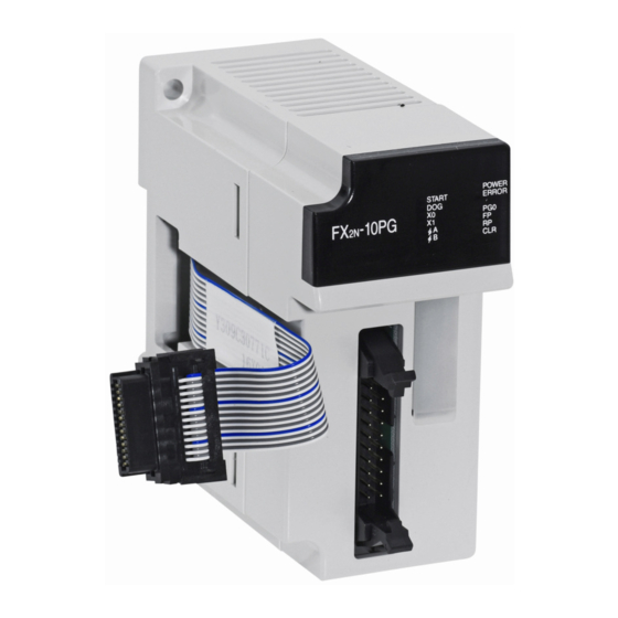
Pulse output block
Hide thumbs
Also See for FX2N-10PG:
- Hardware manual (154 pages) ,
- Hardware manual (140 pages) ,
- Training manual (284 pages)
Table of Contents
Advertisement
Quick Links
Advertisement
Table of Contents

Related Manuals for Mitsubishi Electric FX2N-10PG


Summary of Contents for Mitsubishi Electric FX2N-10PG
- Page 1 USER’S MANUAL -10PG...
- Page 2 Model FX2N-10PG Pulse Output Block Foreword • This manual contains text, diagrams and explanations which will guide the reader in the correct installation and operation of the FX -10PG Pulse Output Block. It should be read and understood before attempting to install or use the unit.
- Page 3 This manual confers no industrial property rights or any rights of any other kind, nor does it confer any patent licenses. Mitsubishi Electric Corporation cannot be held responsible for any problems involving industrial property rights which may occur as a result of using the contents noted in this manual.
- Page 4 Model FX2N-10PG Pulse Output Block...
- Page 5 Model FX2N-10PG Pulse Output Block Guidelines for the Safety of the User and Protection of the FX -10PG Pulse Output Block This manual provides information for the use of the FX -10PG Pulse Output Block. The manual has been written to be used by trained and competent personnel. The definition of such a person or persons is as follows;...
- Page 6 Model FX2N-10PG Pulse Output Block • Under no circumstances will Mitsubishi Electric be liable or responsible for any consequential damage that may arise as a result of the installation or use of this equipment. • All examples and diagrams shown in this manual are intended only as an aid to understanding the text, not to guarantee operation.
- Page 7 Model FX2N-10PG Pulse Output Block Associated Manuals This manual describes the handling and operation of MELSEC-FX Series FX -10PG Pulse Output Block. For the configuration and commands of the system, also refer to the manuals of the following PLC. Before operation, read this manual and the manuals of the PLC thoroughly and be sure you sufficiently understand their specifications for proper operation.
- Page 8 Model FX2N-10PG Pulse Output Block...
-
Page 9: Table Of Contents
Model FX2N-10PG Pulse Output Block Contents 1. Introduction ..................1-1 Product outline ....................1-1 2. Outside dimensions and component names ........2-1 Outside dimensions ..................2-1 LED display...................... 2-2 Pin layout and assignment................2-3 2.3.1 Applicable connector and cable size ..............2-4 3. - Page 10 Model FX2N-10PG Pulse Output Block Contents 7.2.14 BFM#21 Override setting ................... 7-7 7.2.15 BFM#23, #22 Operation speed current value ............ 7-7 7.2.16 BFM#25, #24 Current address ................7-8 7.2.17 BFM#26 Operation commands ................7-8 7.2.18 BFM#27 Operation pattern................7-11 7.2.19 BFM#28 Status information................
- Page 11 Model FX2N-10PG Pulse Output Block Contents Interrupt 1st-speed positioning operation............8-14 8.5.1 Outline of interrupt 1st-speed positioning operation.......... 8-14 8.5.2 Operation speed....................8-14 8.5.3 Address instruction.................... 8-14 8.5.4 Rotation direction ....................8-14 8.5.5 Positioning complete flag .................. 8-15 8.5.6 STOP command....................8-15 2nd-speed positioning operation..............
- Page 12 Model FX2N-10PG Pulse Output Block Contents Multi-speed operation (table operation) ............9-9 9.3.1 Operation explanation ..................9-10 9.3.2 Device assignment (PLC).................. 9-13 9.3.3 Sequence program.................... 9-15 10. Diagnostics..................10-1 10.1 Diagnostics LED .................... 10-1 10.2 Diagnostics (BFM#37) ................... 10-3 10.3 Diagnostics PLC .................... 10-4...
-
Page 13: Introduction
Model FX2N-10PG Pulse Output Block Introduction 1 Introduction Product outline -10PG Pulse Output Block (hereafter abbreviated as FX -10PG, Pulse Output Block or PGU) is a special block to output a maximum 1MHz pulse array and drive a single-axis stepping motor or servo motor. - Page 14 Model FX2N-10PG Pulse Output Block Introduction 1 MEMO...
-
Page 15: Outside Dimensions And Component Names
Model FX2N-10PG Pulse Output Block Outside dimensions and component names 2 Outside dimensions and component names Outside dimensions Unit: mm (inches) 8 7 ( 3 . 4 3 " ) 4 3 ( 1 . 6 9 " ) 4 ( 0 . 1 6 " ) -
Page 16: Led Display
Model FX2N-10PG Pulse Output Block Outside dimensions and component names 2 LED display LED name State Display content 5V DC is not supplied through the extension cable from the Unlit PLC. POWER 5V DC is supplied through the extension cable from the PLC. -
Page 17: Pin Layout And Assignment
Model FX2N-10PG Pulse Output Block Outside dimensions and component names 2 Pin layout and assignment • The following pin layout is seen when looking at the I/O port in the FX -10PG from the front face. When an I/O cable and connector is prepared by the user, the pin number mark and ▲... -
Page 18: Applicable Connector And Cable Size
Model FX2N-10PG Pulse Output Block Outside dimensions and component names 2 2.3.1 Applicable connector and cable size The connectors for the multi-wire cables are prepared as a set to allow the customer to produce the input/output cables. The cables and crimp tool should be prepared by the customer. -
Page 19: Installation
Model FX2N-10PG Pulse Output Block Installation 3 Installation Install FX -10PG on the right side of the basic unit, extension unit or other extension block of and FX Series PLC. For installation, install the block with DIN rail (DIN46277, 35mm (1.38inches) wide) or directly with M4 screws. - Page 20 Model FX2N-10PG Pulse Output Block Installation 3 Cautions regarding installation 1) Use the block under the environmental conditions specified in the manual. Do not use the unit in a location surrounded by dust, oil fumes, conductive dust, corrosive gas or combustible gas, exposed to high temperature, condensation, wind or rain, or subject to vibration or impact.
-
Page 21: System Configuration
Model FX2N-10PG Pulse Output Block System configuration 4 System configuration Connection with PLC The PLC is connected to FX -10PG with the extension cable. -10PG is handled as a special unit of the PLC and is sequentially given the special unit number of 0 to 7 from the unit which is the nearest to PLC. -
Page 22: Applicable Plc
Model FX2N-10PG Pulse Output Block System configuration 4 Applicable PLC Series name Applicable version Series All versions Series All versions Series All versions Series All versions When connected to an FX Series PLC, the FX -CNV-IF is required. -1PS-5V When connected to an FX... -
Page 23: Specifications
Model FX2N-10PG Pulse Output Block Specifications 5 Specifications General specifications Item Specifications Withstand voltage 500V AC One minute (between all external terminals and ground terminal) The same as the general specifications of the connected PLC Other items (Refer to the PLC manual.) -
Page 24: Input Specifications
Model FX2N-10PG Pulse Output Block Specifications 5 Input specifications φA, φB Item START, DOG, X1 Number of input Three control input points (START, DOG, PG0), two interrupt input points (X0, X1) 2-phase pulse input point (φA, φB) points Input signal 24V DC ±... -
Page 25: Wiring
Model FX2N-10PG Pulse Output Block Wiring 6 Wiring Input output circuit 5 to 24V DC Input terminal -10PG Output terminal Servo amplifier drive unit 7mA/24V DC START 3.3kΩ VIN+ 7mA/24V DC 3.3kΩ VIN- 7mA/24V DC 3.3kΩ 7mA/24V DC 3.3kΩ 24V DC... - Page 26 Model FX2N-10PG Pulse Output Block Wiring 6 • Install a safety circuit outside the FX -10PG so that the entire system conservatively operates even if an abnormality occurs in the external power supply or a failure occurs in the FX -10PG.
- Page 27 Model FX2N-10PG Pulse Output Block Wiring 6 CE EMC Conformity For compliance to CE EMC regulation it is necessary to add a Ferrite filter on the I/O cable of the FX -10PG. The filter should be attached below with the filter surrounding the I/O cable.
-
Page 28: Input Wiring
Model FX2N-10PG Pulse Output Block Wiring 6 Input wiring 6.2.1 START, DOG, X0, X1, S/S External power supply (24V DC) is required for terminals START, DOG, X0, X1 and S/S. Contact output type and open collector transistor output (NPN, PNP) types of external devices are applicable. -
Page 29: A-Phase +, A-Phase -, B-Phase +, B-Phase
Model FX2N-10PG Pulse Output Block Wiring 6 6.2.2 A-phase +, A-phase -, B-phase +, B-phase - The differential line driver or the open collector transistor output type manual pulse generator is applicable to the terminals φA+, φA-, φB+ and φB-. -
Page 30: Pg0
Model FX2N-10PG Pulse Output Block Wiring 6 6.2.3 PG0+, PG0- External power supply (5V DC) is required for the terminals PG0+ and PG0-. The external device of the differential line driver output type or open collector transistor output (NPN/PNP) type is applicable. -
Page 31: Output Wiring
Model FX2N-10PG Pulse Output Block Wiring 6 Output wiring 6.3.1 VIN+, VIN-, FP+, FP-, RP+, RP- The terminals VIN+, VIN-, FP+, FP-, RP+ and RP- are connected to the servo amplifier and motor driver. 5 to 24V DC is supplied to the terminals VIN+ and VIN- from the external power supply or servo amplifier. -
Page 32: Clr+, Clr
Model FX2N-10PG Pulse Output Block Wiring 6 6.3.2 CLR+, CLR- The terminals CLR+ and CLR- are connected to the servo amplifier. 5 to 24V DC is supplied to the terminals CLR+ and CLR- from the external power supply or servo amplifier. -
Page 33: Connection With Stepping Motor
Model FX2N-10PG Pulse Output Block Wiring 6 Connection with stepping motor Power supply DC power type is also available on the PLC. Class D 24V DC ground . Pin layout of port in FX -10PG VIN+ VIN- 3.3kΩ X*** STOP 3.3kΩ... -
Page 34: Connection With Model Mr-C Servo Amplifier
Model FX2N-10PG Pulse Output Block Wiring 6 Connection with Model MR-C Servo Amplifier Power supply DC power type is also available on the PLC. Class D 24V DC ground . Pin layout of port in FX -10PG VIN+ VIN- 3.3kΩ... -
Page 35: Connection With Model Mr-J Servo Amplifier
Model FX2N-10PG Pulse Output Block Wiring 6 Connection with Model MR-J Servo Amplifier Power supply DC power type is also available on the PLC. Class D 24V DC ground . Pin layout of port in FX -10PG VIN+ VIN- 3.3kΩ... -
Page 36: Connection With Model Mr-J2 (-Jr, -Super) Servo Amplifier
Model FX2N-10PG Pulse Output Block Wiring 6 Connection with Model MR-J2 (-Jr, -Super) Servo Amplifier Power supply DC power type is also available on the PLC. Class D 24V DC ground . Pin layout of port in FX -10PG VIN+ VIN- 3.3kΩ... -
Page 37: Connection With Model Mr-H Servo Amplifier
Model FX2N-10PG Pulse Output Block Wiring 6 Connection with Model MR-H Servo Amplifier Power supply DC power type is also available on the PLC. Class D 24V DC ground . Pin layout of port in FX -10PG VIN+ VIN- 3.3kΩ... -
Page 38: Connection With Model Mr-J3 Servo Amplifier
Model FX2N-10PG Pulse Output Block Wiring 6 Connection with Model MR-J3 Servo Amplifier Power supply DC power type is also available on the PLC. Class D 24V DC ground . Pin layout of port in FX -10PG VIN+ VIN- 3.3kΩ... -
Page 39: Connection With Model Mr-Jn Servo Amplifier
Model FX2N-10PG Pulse Output Block Wiring 6 6.10 Connection with Model MR-JN Servo Amplifier Power supply DC power type is also available on the PLC. Class D ground . Pin layout of port in FX -10PG VIN+ VIN- STOP X***... -
Page 40: Connection With Model Mr-J4 Servo Amplifier
Model FX2N-10PG Pulse Output Block Wiring 6 6.11 Connection with Model MR-J4 Servo Amplifier Power supply DC power type is also available on the PLC. . Pin layout of port in FX -10PG Class D ground VIN+ VIN- PG0+ PG0-... -
Page 41: Buffer Memory (Bfm)
Model FX2N-10PG Pulse Output Block Buffer memory (BFM) 7 Buffer memory (BFM) BFM list Initial BFM No. Name Content and setting range Unit Attribute value 1 to 2,147,483,647 User 500,000 Max. speed (The pulse-converted value of unit 1 to 1,000,000Hz) - Page 42 Model FX2N-10PG Pulse Output Block Buffer memory (BFM) 7 Initial BFM No. Name Content and setting range Unit Attribute value ⎯ Status information Refer to 7.2.19 During M code ON : 0 to 32,767 ⎯ M code During M code OFF : -1 ⎯...
- Page 43 Model FX2N-10PG Pulse Output Block Buffer memory (BFM) 7 Initial BFM No. Name Content and setting range Unit Attribute value -2,147,483,648 to 2,147,483,647 Speed information User #103 #102 (The pulse-converted value of (Table No. 0) unit 1 to 1,000,000Hz) m code information ⎯...
- Page 44 Model FX2N-10PG Pulse Output Block Buffer memory (BFM) 7 • A single buffer memory No. is used for 16-bit data, and that of a serial buffer memory No. is used for 32-bit data. Use the 16-bit command (FROM/TO) for the buffer memory of 16-bit data.
-
Page 45: Details Of Bfm
Model FX2N-10PG Pulse Output Block Buffer memory (BFM) 7 Details of BFM 7.2.1 BFM#1, #0 Maximum speed The upper limit of the speed in each operation mode. Set the bias speed (BFM#2), jog speed (BFM#4, #3), zero return speed (high speed) (BFM#6, #5), zero return speed (creep) (BFM#7), operation speed Ι... -
Page 46: Bfm#10, #9 Zero-Point Address
Model FX2N-10PG Pulse Output Block Buffer memory (BFM) 7 7.2.7 BFM#10, #9 Zero-point address The address of the current value at the completion time of zero return operation is set. When the zero return operation is completed, the value is written at the current address (BFM#40, #39). -
Page 47: Bfm#21 Override Setting
Model FX2N-10PG Pulse Output Block Buffer memory (BFM) 7 BFM#18, #17 Target address ΙΙ 7.2.12 The target position (absolute address) or travel distance (relative address) in the 2nd-speed positioning operation is set. When the absolute address is used, the positioning operation is done to the target position specified referring to the current address (BFM#40, #39). -
Page 48: Bfm#25, #24 Current Address
Model FX2N-10PG Pulse Output Block Buffer memory (BFM) 7 7.2.16 BFM#25, #24 Current address The current address data is stored. The stored address data is always the absolute address. Here, the user unit (BFM#36) is selected, and the value which also includes the magnification (BFM#36) of the position data is selected. - Page 49 Model FX2N-10PG Pulse Output Block Buffer memory (BFM) 7 • Detection timing Level detection : Effective while each bit is ON or OFF. Edge detection : The change of OFF or ON is detected to start the operation. • Priority sequence of start flag and stop flag In each operation mode, the STOP command during operation is always valid, and is prior to forward jog, reverse jog and start.
- Page 50 Model FX2N-10PG Pulse Output Block Buffer memory (BFM) 7 • Transfer method of operation command X000 Error reset X001 STOP (N/O contact) X002 Forward limit (N/C contact) X003 Reverse limit X004 Forward jog X005 Reverse jog X006 Zero point return...
-
Page 51: Bfm#27 Operation Pattern
Model FX2N-10PG Pulse Output Block Buffer memory (BFM) 7 7.2.18 BFM#27 Operation pattern The operation pattern executed by FX -10PG is assigned to each bit. TO commands from the PLC select an operation pattern in which it is operated by turning ON/ OFF each bit. -
Page 52: Bfm#28 Status Information
Model FX2N-10PG Pulse Output Block Buffer memory (BFM) 7 • Be sure to produce the program of PLC to make the operation pattern selection earlier than START input or START flag (BFM#26 b9) ON. • When all bits of BFM#27 are OFF or plural bits are ON, the positioning operation will not be started even though START input or START flag (BFM#26 b9) is turned ON. -
Page 53: Bfm#33, #32 Pulse Rate
Model FX2N-10PG Pulse Output Block Buffer memory (BFM) 7 7.2.22 BFM#33, #32 pulse rate Sets how many pulses per motor revolution are given to the drive unit. If any electronic gearing is present in the servo amplifier, it is necessary to consider its magnification. - Page 54 Model FX2N-10PG Pulse Output Block Buffer memory (BFM) 7 • b1, b0 system unit Units handled for the position and speed are set. Bit status Item Details Motor system Controls the position based on “PLS” (pulse). unit Mechanical Controls the position based on “µm, mdeg, 10 inch, etc”.
- Page 55 Model FX2N-10PG Pulse Output Block Buffer memory (BFM) 7 Concept of mechanical system unit When the unit system is set in BFM#36 b1, b2 as machine or compound system, different from the motor system [(b1, b0) = (0, 0)], data is processed in the mechanical system units of mm, deg, or inch.
- Page 56 Model FX2N-10PG Pulse Output Block Buffer memory (BFM) 7 3) When inch is used for setting The following pulses are output for the positioning operation of travel 100 [ × 10 inch] and operation speed of 6 [inch/min]. × Pulse rate...
- Page 57 Model FX2N-10PG Pulse Output Block Buffer memory (BFM) 7 • b8 Pulse output format b8=0: Forward pulses (FP) / reverse pulses (RP) b8=1: Pulses (FP) / direction DIR (RP) Forward Reverse • b9 Rotation direction b9=0: The current value is increased by the forward pulses.
-
Page 58: Bfm#37 Error Code
Model FX2N-10PG Pulse Output Block Buffer memory (BFM) 7 7.2.25 BFM#37 Error code If an error occurs, the error code will be stored in BFM#37. Error code Details No error Not defined. The value setting range is faulty. A value outside the range is set at each BFM. -
Page 59: Bfm#42, #41 Manual Pulse Generator Input Current Value
Model FX2N-10PG Pulse Output Block Buffer memory (BFM) 7 7.2.28 BFM#42, #41 Manual pulse generator input current value Pulses input from the manual pulse generator are stored. Forward increases and reverse decreases the stored value. Here, the stored data does not includes the magnification of the manual pulse generator input electronic gearing (BFM#45, #46). -
Page 60: Bfm#51 Jog Operation Wait Period (In Version 1.70 Or Later)
Model FX2N-10PG Pulse Output Block Buffer memory (BFM) 7 7.2.34 BFM#51 JOG operation WAIT period (in Version 1.70 or later) The waiting period from the time pulse output of one address is started till the continuous pulse output started is written. (Default value: 300ms) BFM#50 must be 1 in order to make the value in BFM#51 valid. -
Page 61: Operation Pattern
Model FX2N-10PG Pulse Output Block Operation pattern 8 Operation pattern General items for positioning operation 8.1.1 Outline of positioning operation Speed Acceleration time Deceleration time (BFM#11) (BFM#12) Maximum speed (BFM#1,#0) Approximate S-shaped control (BFM#36 b11 ON) Operation speed (BFM#16,#15) Trapezoidal control... -
Page 62: Stop Command Process
Model FX2N-10PG Pulse Output Block Operation pattern 8 Item BFM No. Details Maximum speed BFM#1,#0 Upper limit of speed in each operation mode Bias speed BFM#2 The start speed. Operation speed Ι BFM#16,#15 Actual operation speed in each operation mode Actual operation speed during 2nd-speed positioning Operation speed ΙΙ... -
Page 63: Overlapped Command Of Operation Modes
Model FX2N-10PG Pulse Output Block Operation pattern 8 8.1.3 Overlapped command of operation modes Positioning operations are not started even if START is input or START command (BFM#26 b9) is turned ON when plural operation patterns are selected with BFM#27, or the manual pulse generator input operation is selected (plural bits are on). - Page 64 Model FX2N-10PG Pulse Output Block Operation pattern 8 2nd-speed positioning operation 1) When 1st-speed travel is small Deceleration Acceleration time time Approx. S-shaped control (BFM#36 b11 ON) Trapezoidal control (BFM#36 b11 OFF) Operation speed Ι (BFM#16,#15) Operation speed ΙΙ Bias speed...
-
Page 65: Forward/Reverse Limits
Model FX2N-10PG Pulse Output Block Operation pattern 8 8.1.5 Forward/reverse limits -10PG does not name inputs for the forward/reverse limit switches. The switches should be connected to the PLC, the bits b2 (forward limit) and b3 (reverse limit) of BFM#26 are turned ON or OFF with these inputs. -
Page 66: Cautions For Use Of Mechanical System/Compound System Units
Model FX2N-10PG Pulse Output Block Operation pattern 8 8.1.6 Cautions for use of mechanical system/compound system units • Error of output pulse amount When the pulse rate (BFM#33, #32), feed rate (BFM#35, #34) and relative travel distance are designated A, B and C respectively, C × (A/B) expresses the pulse amount which is output from FX -10PG. -
Page 67: Jog Operation
Model FX2N-10PG Pulse Output Block Operation pattern 8 Jog operation 8.2.1 Outline of jog operation Acceleration time Deceleration time (BFM11) (BFM#12) Maximum speed (BFM#1,#0) Jog speed (BFM#4,#3) Bias speed (BFM#2) Time Jog operation input 300ms • Forward pulses are output for forward jog. -
Page 68: Speed Change During Jog Operation
Model FX2N-10PG Pulse Output Block Operation pattern 8 8.2.2 Speed change during jog operation Change with Jog speed setting 10000Hz 7000Hz Time Jog input Jog speed 10000Hz 7000Hz (BFM#4,#3) • When speed change disable (BFM#26 b10) during operation is ON, the change of jog speed (BFM#4, #3) is not permitted. -
Page 69: Machine Zero Return
Model FX2N-10PG Pulse Output Block Operation pattern 8 Machine zero return 8.3.1 Outline of zero return Deceleration time Acceleration time (BFM#12) (BFM#11) Maximum speed (BFM#1,#0) Zero point address (BFM#10, #9) Zero return speed (maximum speed) (BFM#6,#5) Zero return speed (creep) -
Page 70: Zero Return Speed
Model FX2N-10PG Pulse Output Block Operation pattern 8 8.3.5 Zero return speed • Zero return speed (high speed) Set Bias speed (BFM#2) ≤ Zero return speed (high speed) (BFM#6, #5) ≤ Maximum (BFM#1, #0). If Bias speed > Zero return speed (high speed), operation is executed at the bias speed. -
Page 71: Dog Search Function
Model FX2N-10PG Pulse Output Block Operation pattern 8 8.3.9 Dog search function When the forward/reverse limits (BFM#26 b2, b3) are provided, zero return which uses the dog search function can be executed. Zero return direction Reverse limit Forward limit (BFM#26 b3) -
Page 72: 1St-Speed Positioning Operation
Model FX2N-10PG Pulse Output Block Operation pattern 8 1st-speed positioning operation 8.4.1 Outline of 1st-speed positioning operation Deceleration time Deceleration speed (BFM#11) (BFM#12) Maximum speed (BFM#1,#0) Operation speed Ι (BFM#16,#15) Target address Ι (BFM#14,#13) Bias speed (BFM#2) Time START • Positioning operation... -
Page 73: Positioning Complete Flag
Model FX2N-10PG Pulse Output Block Operation pattern 8 8.4.5 Positioning complete flag The positioning complete flag (BFM#28 b6) is reset with START input, START command (BFM#26 b9), forward jog (BFM#26 b4), reverse jog (BFM#26 b5), zero return (BFM#26 b6), data set type zero return (BFM#26 b7), variable-speed operation, manual pulse generator input operation or power shutdown, and is turned ON when the target address is reached. -
Page 74: Interrupt 1St-Speed Positioning Operation
Model FX2N-10PG Pulse Output Block Operation pattern 8 Interrupt 1st-speed positioning operation 8.5.1 Outline of interrupt 1st-speed positioning operation Deceleration time Deceleration speed (BFM#11) (BFM#12) Maximum speed (BFM#1,#0) Operation speed Ι (BFM#16,#15) Target address I (BFM#14,#13) Bias speed (BFM#2) Time... -
Page 75: Positioning Complete Flag
Model FX2N-10PG Pulse Output Block Operation pattern 8 8.5.5 Positioning complete flag The positioning complete flag (BFM#28 b6) is reset with START input, START command (BFM#26 b9), forward jog (BFM#26 b4), reverse jog (BFM#26 b5), zero return (BFM#26 b6), data set type zero return (BFM#26 b7), variable-speed operation, manual pulse generator input operation or power shutdown, and is turned ON when the target address is reached. -
Page 76: 2Nd-Speed Positioning Operation
Model FX2N-10PG Pulse Output Block Operation pattern 8 2nd-speed positioning operation 8.6.1 Outline of 2nd-speed positioning operation Deceleration time Deceleration speed (BFM#11) (BFM#12) Maximum speed (BFM#1,#0) Operation speed Ι (BFM#16,#15) Operation speed ΙΙ (BFM#20,#19) Target address ΙΙ Target address I... -
Page 77: Rotation Direction
Model FX2N-10PG Pulse Output Block Operation pattern 8 8.6.4 Rotation direction Absolute address mode : The rotation direction is determined depending on the large/small relationship between the current address (BFM#25, #24) and target address Ι (BFM#14, #13). Relative address mode : The rotation direction is determined depending on the symbol (positive/negative) of target address Ι... -
Page 78: Speed Switching
Model FX2N-10PG Pulse Output Block Operation pattern 8 8.6.7 Speed switching Speed switching is classified into "standard switching" and "front-load switching". In the FX -10PG, the speed is switched by standard switching. (Refer to the figure below.) <Operation by standard switching>... -
Page 79: Interrupt 2Nd-Speed Positioning Operation
Model FX2N-10PG Pulse Output Block Operation pattern 8 Interrupt 2nd-speed positioning operation 8.7.1 Outline of interrupt 2nd-speed positioning operation Deceleration time Deceleration speed (BFM#11) (BFM#12) Maximum speed (BFM#1,#0) Operation speed ΙΙ Target address I (BFM#20,#19) (BFM#14,#13) Operation speed Ι (BFM#16,#15) -
Page 80: Rotation Direction
Model FX2N-10PG Pulse Output Block Operation pattern 8 8.7.4 Rotation direction Absolute address mode : The rotation direction is determined depending on the large/small relationship between the current address (BFM#25, #24) and target address Ι (BFM#14, #13). Relative address mode : The rotation direction is determined depending on the symbol (positive/negative) of target address Ι. -
Page 81: Interrupt Stop Operation
Model FX2N-10PG Pulse Output Block Operation pattern 8 Interrupt stop operation 8.8.1 Outline of interrupt stop operation Deceleration time Deceleration speed (BFM#11) (BFM#12) Maximum speed (BFM#1,#0) Target address I (BFM#14,#13) Operation speed Ι (BFM#16,#15) Bias speed (BFM#2) Time START Interrupt input (X0) •... -
Page 82: Positioning Complete Flag
Model FX2N-10PG Pulse Output Block Operation pattern 8 8.8.5 Positioning complete flag The positioning complete flag (BFM#28 b6) is reset with START input, START command (BFM#26 b9), forward jog (BFM#26 b4), reverse jog (BFM#26 b5), zero return (BFM#26 b6), data set type zero return (BFM#26 b7), variable-speed operation, manual pulse generator input operation or power shutdown, and is turned ON when the target address is reached. -
Page 83: Outline Of Table Operation
Model FX2N-10PG Pulse Output Block Operation pattern 8 Table operation 8.9.1 Outline of table operation In FX -10PG, the program of positioning control can be produced with a table. When the table operation is used, continuous operation (multi-speed operation) and position- to-speed operation (the work is de-/accelerated to stop at a desired position) become possible. - Page 84 Model FX2N-10PG Pulse Output Block Operation pattern 8 - Operation information Refer to the following table. Setting Name Details value Step-advance When START signal is turned ON, positioning is executed table by operation table. The speed information can be changed during operation.
-
Page 85: Assignment Of Tables And Bfm Nos
Model FX2N-10PG Pulse Output Block Operation pattern 8 8.9.2 Assignment of tables and BFM Nos. Table Position Speed m code Operation information information information information BFM#101, #100 BFM#103, #102 BFM#104 BFM#105 BFM#107, #106 BFM#109, #108 BFM#110 BFM#111 BFM#113, #112 BFM#115, #114... -
Page 86: Operation Example 2 (Position-To-Speed Operation)
Model FX2N-10PG Pulse Output Block Operation pattern 8 • Speed switching Speed switching is classified into "standard switching" and "front-load switching". In the FX -10PG, the speed is switched by standard switching. (Refer to the figure below.) <Operation by standard switching>... -
Page 87: Operation Example 3 (Step-Advance Operation)
Model FX2N-10PG Pulse Output Block Operation pattern 8 8.9.5 Operation example 3 (step-advance operation) When the absolute address assignment and table start No. are 0, the current address at the time of START is 0. Deceleration time Deceleration speed (BFM#11) -
Page 88: Variable-Speed Operation
Model FX2N-10PG Pulse Output Block Operation pattern 8 8.10 Variable-speed operation 8.10.1 Outline of variable-speed operation Deceleration time Deceleration speed (BFM#11) (BFM#12) Maximum speed (BFM#1,#0) Operation speed Ι (BFM#16,#15) Bias speed (BFM#2) Time Operation speed Ι 1400 1000 (BFM#16,#15) • Positioning operation When the variable-speed operation (BFM#27 b6) operation pattern is selected, the work is accelerated to operation speed Ι... -
Page 89: Rotation Direction
Model FX2N-10PG Pulse Output Block Operation pattern 8 8.10.3 Rotation direction The rotation direction is determined depending on whether the operation speed Ι (BFM#16, #15) is positive or negative. When operation speed Ι is positive, the current value is increased. -
Page 90: Manual Pulse Generator Input Operation
Model FX2N-10PG Pulse Output Block Operation pattern 8 8.11 Manual pulse generator input operation 8.11.1 Outline of manual pulse generator input operation • When the manual pulse generator input operation (BFM#27 b7) operation pattern is ON, operation with the manual pulse generator input is possible. -
Page 91: Pulse Output Valid Range
Model FX2N-10PG Pulse Output Block Operation pattern 8 The output pulse (frequency and pulse amount) of FX -10PG is gained as follows: Input pulse (frequency and pulse amount) from the manual pulse generator × manual pulse generator input electronic gearing (BFM#45 / BFM#46) If the value of the manual pulse generator input electronic gearing is less than 1/1, one pulse is output for plural input pulses. - Page 92 Model FX2N-10PG Pulse Output Block Operation pattern 8 MEMO 8-32...
-
Page 93: Program Example
Model FX2N-10PG Pulse Output Block Program example 9 Program example Outline of FROM/TO commands -10PG reads and writes the travel, operation speed and operation pattern with FROM/TO commands of PLC. FROM/TO commands are outlined as follows. D • FNC78 X010 BFM#26 to #27 of special unit No. -
Page 94: Length Feed Operation (1St-Speed Positioning)
Model FX2N-10PG Pulse Output Block Program example 9 Length feed operation (1st-speed positioning) The program example of the length feed operation (1st-speed positioning) is described. Moreover, also in this example, the forward/reverse operation and zero return operation are possible in the jog operation mode. -
Page 95: Operation Explanation
Model FX2N-10PG Pulse Output Block Program example 9 9.2.1 Operation explanation • Zero return operation 1) When X006 in the PLC is turned ON, the zero return operation is started in the decreasing direction of the current value. 2) When the dog input is turned ON, the work is decelerated to the creep speed. - Page 96 Model FX2N-10PG Pulse Output Block Program example 9 • Jog operation 1) When X004 in the PLC is turned ON, jog operation is executed in the forward direction. When X005 is turned ON, jog operation is executed in the reverse direction.
- Page 97 Model FX2N-10PG Pulse Output Block Program example 9 • Length feed (1st-speed positioning) 1) When X007 in the PLC is turned ON, the work moves a specified distance in the forward direction, and is decelerated and stopped. If X007 is turned ON again, the work will move the same distance. (Relative position...
-
Page 98: Device Assignment (Plc)
Model FX2N-10PG Pulse Output Block Program example 9 9.2.2 Device assignment (PLC) Element Element No. Assignment X000 Error reset X001 Stop X002 Forward limit (The external wiring is the N/C contact.) X003 Reverse limit (The external wiring is the N/C contact.) -
Page 99: Sequence Program
Model FX2N-10PG Pulse Output Block Program example 9 9.2.3 Sequence program Example using the FROM and TO commands (Initial pulse) M8002 Maximum speed (500,000Hz) K500000 Bias speed (0Hz) Jog speed (10,000Hz) K10000 Zero return speed (high speed) K100000 (100,000Hz) Creep speed (1,000Hz) - Page 100 Model FX2N-10PG Pulse Output Block Program example 9 (Initial pulse) M8002 Target address setting DMOV K100000 (100,000 pulses) Operation speed setting DMOV K30000 (30,000Hz) (RUN monitor) M8000 Target address Ι Operation speed Ι (Error reset input) X000 Error reset (STOP input)
-
Page 101: Multi-Speed Operation (Table Operation)
Model FX2N-10PG Pulse Output Block Program example 9 Multi-speed operation (table operation) A program example for multi-speed operation (table operation) is described. Moreover, also in this example, the forward/reverse operation and zero return operation are possible in the jog operation mode. -
Page 102: Operation Explanation
Model FX2N-10PG Pulse Output Block Program example 9 9.3.1 Operation explanation • Zero return operation 1) When X006 in the PLC is turned ON, the zero return operation is stared in the decreasing direction of the current value. (Only when m code is OFF, the zero return operation can be started.) 2) When the jog input is turned ON, the work is decelerated to the creep speed. - Page 103 Model FX2N-10PG Pulse Output Block Program example 9 • Jog operation 1) When X004 in the PLC is turned ON, jog operation is executed in the forward direction. When X005 is turned ON, jog operation is executed in the reverse direction.
- Page 104 Model FX2N-10PG Pulse Output Block Program example 9 • Multi-speed operation (table operation) 1) When X007 in the PLC is turned ON, the multi-speed operation is started in the forward direction. 2) The operation speed has three steps, and an m code is turned ON according to each step.
-
Page 105: Device Assignment (Plc)
Model FX2N-10PG Pulse Output Block Program example 9 9.3.2 Device assignment (PLC) Element Element No. Assignment X000 Error reset X001 STOP X002 Forward limit (External wiring is the N/C contact.) X003 Reverse limit (External wiring is the N/C contact.) Input... - Page 106 Model FX2N-10PG Pulse Output Block Program example 9 Element Element No. Assignment D23,D22 Output frequency D25,D24 Current address (user unit) Status Error code Terminal information D40,D39 Current address (Pulse-converted value) D101,D100 Position information of table No. 0 D103,D102 Speed information of table No. 0 D104 m code information of table No.
-
Page 107: Sequence Program
Model FX2N-10PG Pulse Output Block Program example 9 9.3.3 Sequence program Example using the FROM and TO commands M8002 (Initial pulse) K500000 Maximum speed (500,000Hz) Bias speed (0Hz) K10000 Jog speed (10,000Hz) Zero return speed (high speed) K1000000 (100,000Hz) K1000... - Page 108 Model FX2N-10PG Pulse Output Block Program example 9 (Initial pulse) M8002 Position information of table DMOV K500 D100 No. 0 (500 pulses) Speed information of table DMOV K500 D102 No. 0 (500Hz) m code information of table K1200 D104 No. 0 (m1200)
- Page 109 Model FX2N-10PG Pulse Output Block Program example 9 (Error reset input) X000 Error reset (STOP input) X001 STOP (Forward rotation limit input) X002 Forward limit (Reverse rotation limit input) X003 Reverse limit (Forward jog input) (Reverse jog) X004 Forward jog...
- Page 110 Model FX2N-10PG Pulse Output Block Program example 9 MEMO 9-18...
-
Page 111: Diagnostics
Model FX2N-10PG Pulse Output Block Diagnostics 10 Diagnostics If any trouble occurs, first check for loose terminal screws on the power supply unit, PLC and I/ O devices, and for poor contacts on FX -10PG, and the connectors of the motor drivers and servo amplifier. - Page 112 Model FX2N-10PG Pulse Output Block Diagnostics 10 Status Display details Countermeasure name • If LED is not lit when dog input is turned on, check the input wiring. The external power Unlit. Dog input OFF supply (24V DC) is necessary for START, DOG, X0 and X1 input of FX -10PG.
-
Page 113: Diagnostics (Bfm#37)
Model FX2N-10PG Pulse Output Block Diagnostics 10 10.2 Diagnostics (BFM#37) If an error occurs, the error code will be stored into BFM#37. Error code Details Countermeasure ⎯ No error ⎯ Not defined. Value setting range defect Change the setting value of the relevant A value outside the settable value range is buffer memory to within the setting range. -
Page 114: Diagnostics Plc
Model FX2N-10PG Pulse Output Block Diagnostics 10 10.3 Diagnostics PLC If any trouble occurs in the PLC connected to FX -10PG, FX -10PG will not properly operate since FROM/TO commands may not the provided. Some errors which can be checked with PLC are partially described as follows: For details of the wiring, special auxiliary relay and special data registers, refer to the PLC instruction manual. - Page 116 USER’S MANUAL -10PG HEAD OFFICE: TOKYO BUILDING, 2-7-3 MARUNOUCHI, CHIYODA-KU, TOKYO 100-8310, JAPAN FX2N-10PG-U-E MODEL 09R611 MODEL CODE JY992D93401L Effective August 2016 (MEE) Specifications are subject to change without notice.
Need help?
Do you have a question about the FX2N-10PG and is the answer not in the manual?
Questions and answers