Dell PowerEdge M830 Owner's Manual
Blade server
Hide thumbs
Also See for PowerEdge M830:
- Owner's manual (131 pages) ,
- Owner's manual (133 pages) ,
- Getting started (2 pages)
Table of Contents
Advertisement
Quick Links
Advertisement
Table of Contents
Troubleshooting

Related Manuals for Dell PowerEdge M830


Summary of Contents for Dell PowerEdge M830
- Page 1 Dell PowerEdge M830 Owner's Manual Regulatory Model: FHB Regulatory Type: FHB008...
- Page 2 © 2016 Dell Inc. All rights reserved. This product is protected by U.S. and international copyright and intellectual property laws. Dell and the Dell logo are trademarks of Dell Inc. in the United States and/or other jurisdictions. All other marks and names mentioned herein may be trademarks of their respective companies.
-
Page 3: Table Of Contents
Contents 1 Dell PowerEdge M830 system overview............8 ..............8 Supported configurations for the PowerEdge M830 system .............................9 Front panel ..............10 Front panel view—2.5-inch hard drive or SSD system ..................11 Front panel view—1.8-inch SSD system ..................11 Using USB diskette or USB DVD or CD drives ....................12... - Page 4 System Setup details ..........................29 System BIOS ........................51 iDRAC Settings utility ..........................52 Device Settings ........................52 Dell Lifecycle Controller ....................52 Embedded systems management ............................53 Boot Manager ........................53 Viewing Boot Manager ......................53 Boot Manager main menu ..............................
- Page 5 ......................78 Installing a mezzanine card ......................79 Mezzanine card support bracket ................79 Removing the mezzanine card support bracket ................81 Installing the mezzanine card support bracket ....................82 Internal dual SD module (optional) ........................82 Replacing an SD card ..........................
- Page 6 ....................155 Initializing the TPM for TXT users 7 Using system diagnostics................156 ........................156 Dell Online Diagnostics ....................156 Dell Embedded System Diagnostics ..............156 When to use the Embedded System Diagnostics ................157 Running the Embedded System Diagnostics ....................... 157 System diagnostics controls 8 Jumpers and connectors................
- Page 7 Troubleshooting the blade system board .................. 166 Troubleshooting the NVRAM backup battery ..........................167 System messages ........................167 Warning messages ........................167 Diagnostic messages ..........................167 Alert messages 10 Getting help.....................168 ..........................168 Contacting Dell ...................168 Accessing system information by using QRL ......................168 Quick Resource Locator...
-
Page 8: Dell Poweredge M830 System Overview
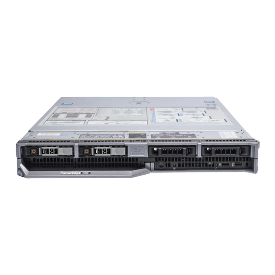
Dell PowerEdge M830 system overview The Dell PowerEdge M830 system is a full-height blade that is configured for the PowerEdge M1000e enclosure. The Dell PowerEdge M830 system supports up to: • Four Intel Xeon E5-4600 v4 or v3 processors •... -
Page 9: Front Panel
Figure 1. Supported configurations for the Dell PowerEdge M830 system Front panel The front panel provides access to the features available on the front of the server, such as the power button, status indicator, management indicator, and USB ports. The diagnostic LEDs or the LCD panel is... -
Page 10: Front Panel View-2.5-Inch Hard Drive Or Ssd System
Direct port Direct features. For more information about iDRAC, see the iDRAC Guide at Dell.com/idracmanuals. Management indicator The management indicator glows when the iDRAC controls the USB connector for management functions. -
Page 11: Front Panel View-1.8-Inch Ssd System
Direct port Direct features. For more information about iDRAC, see the iDRAC Guide at Dell.com/idracmanuals. Management indicator The management indicator glows when the iDRAC controls the USB connector for management functions. -
Page 12: Diagnostic Indicators On The Front Panel
Restart the system Enter System Setup Set the drive as first in the boot sequence The USB device is displayed in the Boot Order Setup screen only if it is attached to the system before you run the System Setup. You can also select the boot device by pressing F11 during system start-up and selecting a boot device for the current boot sequence. -
Page 13: Idrac Direct Led Indicator Codes
Drive-status indicator pattern Condition NOTE: The drive status indicator remains off until all hard drives are initialized after the system is turned on. Drives are not ready for insertion or removal during this time. Flashes green, amber, and turns off Predicted drive failure Flashes amber four times per second Drive failed... -
Page 14: Locating Service Tag Of Your System
Code and Service Tag are found on the front of the system by pulling out the information tag. Alternatively, the information may be on a sticker on the chassis of the system. This information is used by Dell to route support calls to the appropriate personnel. -
Page 15: Documentation Resources
For information about iDRAC features, Dell.com/idracmanuals system configuring and logging in to iDRAC, and managing your system remotely, see the Integrated Dell Remote Access Controller User's Guide. For information about installing the Dell.com/operatingsystemmanuals operating system, see the operating system documentation. - Page 16 OpenManage Essentials, see the Dell OpenManage Essentials User’s Guide. For information about installing and Dell.com/DSET using Dell System E-Support Tool (DSET), see the Dell System E-Support Tool (DSET) User's Guide. For information about installing and Dell.com/asmdocs using Active System Manager (ASM), see the Active System Manager User’s...
- Page 17 Task Document Location the Dell Event and Error Messages Reference Guide.
-
Page 18: Technical Specifications
Chassis weight Maximum chassis weight of the PowerEdge M830 system is 14.5 kg (31.9 lb). Processor specification The PowerEdge M830 system supports up to four Intel Xeon E5-4600 v3 or v4 product family processors. System battery specification The PowerEdge M830 system supports CR 2032 3.0-V lithium coin cell system battery. -
Page 19: Raid Controller Specifications
NOTE: One SD card is dedicated for future vFlash support. Mezzanine card specification The PowerEdge M830 system supports four PCIe x8 Gen 3 slots mezzanine card supporting dual-port 10 Gb Ethernet, quad port 1 Gb, FC8 Fiber Channel, FC16 Fiber Channel, or Infiniband mezzanine cards. -
Page 20: Video Specifications
Video specifications The PowerEdge M830 system supports Matrox G200 VGA controller integrated with iDRAC and 2 GB video memory is shared with iDRAC application memory. Environmental specifications NOTE: For additional information about environmental measurements for specific system configurations, see Dell.com/environmental_datasheets. -
Page 21: Particulate And Gaseous Contamination Specifications
Table 13. Maximum altitude specifications Maximum altitude Specifications Operating 3048 m (10,000 ft) Storage 12,000 m (39,370 ft) Table 14. Operating temperature de-rating specification Operating temperature de-rating Specifications Up to 35°C (95°F) Maximum temperature is reduced by 1°C/300 m (1°F/547 ft), above 950 m (3,117 ft). -
Page 22: Expanded Operating Temperature
Table 16. Gaseous contamination specifications Gaseous contamination Specifications Copper Coupon Corrosion <300 Å/month per Class G1 as defined by ANSI/ ISA71.04-1985. Silver Coupon Corrosion <200 Å/month as defined by AHSRAE TC9.9. NOTE: Maximum corrosive contaminant levels measured at ≤50% relative humidity. Expanded operating temperature Table 17. - Page 23 LRDIMMs 130 W or 120 W all core processors Non Dell-qualified peripheral cards and/or peripheral cards greater than 25 W...
-
Page 24: Initial System Setup And Configuration
Log in to iDRAC iDRAC configuration The Integrated Dell Remote Access Controller (iDRAC) is designed to make system administrators more productive and improve the overall availability of Dell systems. iDRAC alerts administrators to system issues, helps them perform remote system management, and reduces the need for physical access to the system. -
Page 25: Options To Install The Operating System
Smart Card. NOTE: You must have iDRAC credentials to log in to iDRAC. For more information about logging in to iDRAC and iDRAC licenses, see the Integrated Dell Remote Access Controller User's Guide at Dell.com/idracmanuals. Options to install the operating system... -
Page 26: Methods To Download Firmware And Drivers
Using Dell OpenManage Deployment Toolkit (DTK) Dell.com/openmanagemanuals Downloading the drivers and firmware Dell recommends that you download and install the latest BIOS, drivers, and systems management firmware on your system. Prerequisites Ensure that you clear the web browser cache before downloading the drivers and firmware. -
Page 27: Pre-Operating System Management Applications
Options to manage the pre-operating system applications Your system has the following options to manage the pre-operating system applications: • System Setup • Boot Manager • Dell Lifecycle Controller • Preboot Execution Environment (PXE) Related Links System Setup Boot Manager Dell Lifecycle Controller PXE boot... -
Page 28: Viewing System Setup
UEFI (Unified Extensible Firmware Interface). You can enable or disable various iDRAC parameters by using the iDRAC settings utility. For more information about this utility, see Integrated Dell Remote Access Controller User’s Guide at Dell.com/idracmanuals. Device Settings Enables you to configure device settings. -
Page 29: System Bios
System BIOS You can use the System BIOS screen to edit specific functions such as boot order, system password, setup password, set the RAID mode, and enable or disable USB ports. Related Links System BIOS Settings details Boot Settings Network Settings System Security System Information Memory Settings... - Page 30 Option Description Boot Settings Specifies options to specify the boot mode (BIOS or UEFI). Enables you to modify UEFI and BIOS boot settings. Network Settings Specifies options to change the network settings. Integrated Specifies options to manage integrated device controllers and ports and specify Devices related features and options.
- Page 31 Boot Settings details The Boot Settings screen details are explained as follows: Option Description Boot Mode Enables you to set the boot mode of the system. CAUTION: Switching the boot mode may prevent the system from booting if the operating system is not installed in the same boot mode. If the operating system supports UEFI, you can set this option to UEFI.
- Page 32 NOTE: For the latest information about supported operating systems, go to Dell.com/ossupport. Related Links Boot Settings Boot Settings details Viewing Boot Settings Changing the boot order You may have to change the boot order if you want to boot from a USB key or an optical drive. The following instructions may vary if you have selected BIOS for Boot Mode.
- Page 33 Network Settings screen details The Network Settings screen details are explained as follows: Option Description PXE Device n (n = Enables or disables the device. When enabled, a UEFI boot option is created for the 1 to 4) device. PXE Device n Enables you to control the configuration of the PXE device.
- Page 34 Related Links UEFI iSCSI Settings Viewing UEFI iSCSI Settings System Security You can use the System Security screen to perform specific functions such as setting the system password, setup password and disabling the power button. Related Links System Security Settings details Operating with a setup password enabled System BIOS Viewing System Security...
- Page 35 Option Description TXT fields if the TPM Status field is set to either On with Pre-boot Measurements or On without Pre-boot Measurements. TPM Information Changes the operational state of the TPM. This option is set to No Change by default. TPM Status Specifies the TPM status.
- Page 36 In the System Password field, type your system password, and press Enter or Tab. Use the following guidelines to assign the system password: • A password can have up to 32 characters. • The password can contain the numbers 0 through 9. •...
- Page 37 In the Setup Password field, alter or delete the existing setup password, and then press Enter or Tab. If you change the system and setup password, a message prompts you to reenter the new password. If you delete the system and setup password, a message prompts you to confirm the deletion. Press Esc to return to the System BIOS screen.
- Page 38 Option Description Key Exchange Key Enables you to import, export, delete, or restore entries in the Key Exchange Key Database (KEK) Database. Authorized Imports, exports, deletes, or restores entries in the Authorized Signature Database Signature (db). Database Forbidden Imports, exports, deletes, or restores entries in the Forbidden Signature Database Signature (dbx).
- Page 39 Option Description System Specifies the name of the system manufacturer. Manufacturer System Specifies the contact information of the system manufacturer. Manufacturer Contact Information System CPLD Specifies the current version of the system complex programmable logic device Version (CPLD) firmware. UEFI Compliance Specifies the UEFI compliance level of the system firmware.
- Page 40 Operating Mode Advanced ECC Mode, Mirror Mode, Spare Mode, Spare with Advanced ECC Mode, Dell Fault Resilient Mode and Dell NUMA Fault Resilient Mode. This option is set to Optimizer Mode by default. NOTE: The Memory Operating Mode option can have different default and available options based on the memory configuration of your system.
- Page 41 On the System BIOS screen, click Processor Settings. Related Links Processor Settings Processor Settings details Processor Settings details The Processor Settings screen details are explained as follows: Option Description Logical Processor Enables or disables the logical processors and displays the number of logical processors.
- Page 42 Option Description Dell Controlled Controls the turbo engagement. Enable this option only when System Profile is set Turbo to Performance. NOTE: Depending on the number of installed CPUs, there may be up to four processor listings. Number of Cores Controls the number of enabled cores in each processor. This option is set to All per Processor by default.
- Page 43 On the System Setup Main Menu screen, click System BIOS. On the System BIOS screen, click SATA Settings. Related Links SATA Settings SATA Settings details SATA Settings details The SATA Settings screen details are explained as follows: Option Description Embedded SATA Enables the embedded SATA option to be set to Off, ATA, AHCI, or RAID modes.
- Page 44 Option Description Option Description Model Specifies the drive model of the selected device. Drive Type Specifies the type of drive attached to the SATA port. Capacity Specifies the total capacity of the hard drive. This field is undefined for removable media devices such as optical drives.
- Page 45 Option Description Port G Sets the drive type of the selected device. For Embedded SATA settings in ATA mode, set this field to Auto to enable BIOS support. Set it to OFF to turn off BIOS support. For AHCI or RAID mode, BIOS support is always enabled. Option Description Model...
- Page 46 Option Description Option Description Capacity Specifies the total capacity of the hard drive. This field is undefined for removable media devices such as optical drives. Related Links SATA Settings Viewing SATA Settings Integrated Devices You can use the Integrated Devices screen to view and configure the settings of all integrated devices including the video controller, integrated RAID controller, and the USB ports.
- Page 47 Option Description Internal USB Port Enables or disables the internal USB port. This option is set to Enabled by default. Integrated RAID Enables or disables the integrated RAID controller. This option is set to Enabled by Controller default. Integrated Enables or disables the integrated network card. Network Card 1 I/OAT DMA Engine Enables or disables the I/OAT option.
- Page 48 On the System BIOS screen, click Serial Communication. Related Links Serial Communication Serial Communication details Serial Communication details The Serial Communication screen details are explained as follows: Option Description Serial Enables the COM port or Console Redirection options. This option is set to Off by Communication default.
- Page 49 Custom, the BIOS automatically sets the rest of the options. You can only change the rest of the options if the mode is set to Custom. This option is set to Performance Per Watt Optimized (DAPC) by default. DAPC is Dell Active Power Controller.
- Page 50 Option Description either save power or optimize performance is influenced by the setting of the Energy Efficiency Policy option. Energy Efficient Enables you to select the Energy Efficient Policy option. Policy The CPU uses the setting to manipulate the internal behavior of the processor and determines whether to target higher performance or better power savings.
-
Page 51: Idrac Settings Utility
NOTE: Accessing some of the features on the iDRAC settings utility needs the iDRAC Enterprise License upgrade. For more information about using iDRAC, see Dell Integrated Dell Remote Access Controller User's Guide at Dell.com/idracmanuals. Related Links... -
Page 52: Device Settings
The Dell Lifecycle Controller provides advanced embedded systems management throughout the system’s lifecycle. The Dell Lifecycle Controller can be started during the boot sequence and can function independently of the operating system. NOTE: Certain platform configurations may not support the full set of features provided by the Dell Lifecycle Controller. -
Page 53: Boot Manager
For more information about setting up the Dell Lifecycle Controller, configuring hardware and firmware, and deploying the operating system, see the Dell Lifecycle Controller documentation at Dell.com/ idracmanuals. Related Links Dell Lifecycle Controller Boot Manager The Boot Manager screen enables you to select boot options and diagnostic utilities. -
Page 54: Pxe Boot
One-shot BIOS boot menu One-shot BIOS boot menu enables you to select a boot device to boot from. Related Links Boot Manager System Utilities System Utilities contains the following utilities that can be launched: • Launch Diagnostics • BIOS Update File Explorer •... -
Page 55: Installing And Removing Blade Components
Damage due to servicing that is not authorized by Dell is not covered by your warranty. Read and follow the safety instructions that are shipped with your product. -
Page 56: Recommended Tools
Damage due to servicing that is not authorized by Dell is not covered by your warranty. Read and follow the safety instructions that are shipped with your product. -
Page 57: Installing A Blade
Damage due to servicing that is not authorized by Dell is not covered by your warranty. Read and follow the safety instructions that came with the product. - Page 58 Steps If you are installing a new blade, remove the plastic cover from the I/O connector(s) and save for future use. Orient the blade so that the handle is on the left side of the blade. If you are installing the full-height blade in bays 3 or 4, rotate the LCD module to the horizontal storage position to prevent accidental damage to the LCD screen.
-
Page 59: System Cover
Damage due to servicing that is not authorized by Dell is not covered by your warranty. Read and follow the safety instructions that came with the product. -
Page 60: Installing The System Cover
Damage due to servicing that is not authorized by Dell is not covered by your warranty. Read and follow the safety instructions that came with the product. - Page 61 NOTE: You must remove the system cover to service other components inside the system. Ensure that no tools or parts are left inside the blade. Steps Align the alignment guide on the system cover with the alignment guide on the chassis. Lower the cover onto the chassis.
-
Page 62: Inside The Blade
Related Links Safety instructions Before working inside your system Removing the system cover Installing a blade After working inside your system Inside the blade Figure 10. Inside the blade mezzanine card connectors for card 1 and card restore Serial Peripheral Interface (rSPI) card mezzanine card connectors for card 3 and Network Daughter Card (NDC) card 4... -
Page 63: Cooling Shroud
Damage due to servicing that is not authorized by Dell is not covered by your warranty. Read and follow the safety instructions that are shipped with your product. -
Page 64: Installing The Cooling Shroud
Damage due to servicing that is not authorized by Dell is not covered by your warranty. Read and follow the safety instructions that came with the product. -
Page 65: System Memory
Related Links Safety instructions Before working inside your system Removing the cooling shroud After working inside your system System memory Your system supports DDR4 registered DIMMs (RDIMMs) and load reduced DIMMs (LRDIMMs). It supports DDR4 voltage specifications. NOTE: MT/s indicates DIMM speed in MegaTransfers per second. Memory bus operating frequency can be either 2400 MT/s, 2133 MT/s, and 1866 MT/s depending on the: •... - Page 66 Figure 13. Memory socket locations Memory channels are organized as follows: Processor 1 channel 0: memory sockets A1, A5, and A9 channel 1: memory sockets A2, A6, and A10 channel 2: memory sockets A3, A7, and A11 channel 3: memory sockets A4, A8, and A12 Processor 2 channel 0: memory sockets B1, B5, and B9 channel 1: memory sockets B2, B6, and B10...
-
Page 67: General Memory Module Installation Guidelines
channel 3: memory sockets B4, B8, and B12 Processor 3 channel 0: memory sockets C1, C5, and C9 channel 1: memory sockets C2, C6, and C10 channel 2: memory sockets C3, C7, and C11 channel 3: memory sockets C4, C8, and C12 Processor 4 channel 0: memory sockets D1, D5, and D9 channel 1: memory sockets D2, D6, and D10... -
Page 68: Mode-Specific Guidelines
• Populate the sockets by highest capacity DIMM in the following order - first in sockets with white release levers and then black. For example, if you want to mix 16 GB and 8 GB DIMMs, populate 16 GB DIMMs in the sockets with white release tabs and 8 GB DIMMs in the sockets with black release tabs. •... -
Page 69: Sample Memory Configurations
Memory sparing NOTE: To use memory sparing, this feature must be enabled in System Setup. In this mode, one rank per channel is reserved as a spare. If persistent correctable errors are detected on a rank, the data from this rank is copied to the spare rank, and the failed rank is disabled. With memory sparing enabled, the system memory available to the operating system is reduced by one rank per channel. - Page 70 System capacity DIMM size (in Number of Organization and DIMM slot population (in GB) DIMMs speed 1R x8, 2400 MT/s A1, A2, A3, A4, B1, B2, B3, 2R x8, 2133 MT/s A1, A2, A3, A4, B1, B2, B3, 1R x8, 2133 MT/s A1, A2, A3, A4, A5, A6, A7, A8, A9, A10, A11, A12, B1, B2, B3, B4, B5, B6, B7, B8,...
- Page 71 System capacity DIMM size (in Number of Organization and DIMM slot population (in GB) DIMMs speed B2, B3, B4, B5, B6, B7, B8, B9, B10, B11, B12 2R, x4, 2400 MT/s A1, A2, A3, A4, A5, A6, A7, A8, B1, B2, B3, B4, B5, B6, B7, B8 4R, x4, 2133 MT/s A1, A2, A3, A4, A5, A6, A7,...
- Page 72 System capacity DIMM size (in Number of Organization and DIMM slot population (in GB) DIMMs speed B9, B10, B11, B12, C1, C2, C3, C4, C5, C6, C7, C8, C9, C10, C11, C12, D1, D2, D3, D4, D5, D6, D7, D8, D9, D10, D11, D12 2R x8, 2400 MT/s A1, A2, A3, A4, A5, A6, B1,...
-
Page 73: Removing Memory Modules
Damage due to servicing that is not authorized by Dell is not covered by your warranty. Read and follow the safety instructions that are shipped with your product. -
Page 74: Installing Memory Modules
Figure 14. Removing the memory module memory module memory module socket memory module socket ejector (2) Next steps Install the memory module. NOTE: If you are removing the memory module permanently, install a memory module blank. Install the cooling shroud. Follow the procedure listed in the After working inside your system section. - Page 75 Damage due to servicing that is not authorized by Dell is not covered by your warranty. Read and follow the safety instructions that are shipped with your product.
-
Page 76: I/O Module Mezzanine Cards
I/O module(s). For more information on I/O modules, see "Guidelines for Installing I/O Modules" in the M1000e Enclosure Owner's Manual at dell.com/support/home. Mezzanine card installation guidelines The blade supports up to four mezzanine cards:... -
Page 77: Removing A Mezzanine Card
Damage due to servicing that is not authorized by Dell is not covered by your warranty. Read and follow the safety instructions that are shipped with your product. -
Page 78: Installing A Mezzanine Card
Damage due to servicing that is not authorized by Dell is not covered by your warranty. Read and follow the safety instructions that are shipped with your product. -
Page 79: Mezzanine Card Support Bracket
Damage due to servicing that is not authorized by Dell is not covered by your warranty. Read and follow the safety instructions that came with the product. - Page 80 Steps Remove the screw that secures the mezzanine card support bracket to the system board. Orient the mezzanine card support bracket upward and slide it until the tabs on the mezzanine card support bracket disengage from the slots on the system. Lift the mezzanine card support bracket away from the system.
-
Page 81: Installing The Mezzanine Card Support Bracket
Damage due to servicing that is not authorized by Dell is not covered by your warranty. Read and follow the safety instructions that came with the product. -
Page 82: Internal Dual Sd Module (Optional)
Damage due to servicing that is not authorized by Dell is not covered by your warranty. Read and follow the safety instructions that are shipped with your product. -
Page 83: Internal Usb Key
Steps Locate the SD card slot on the internal dual SD module (IDSDM) card. Press inward on the card to release it from the slot, and remove the card. Figure 20. Replacing an SD card IDSDM card SD card upper card slot (SD 2) lower card slot (SD 1) Next steps Follow the procedure listed in the After working inside your system section. - Page 84 Damage due to servicing that is not authorized by Dell is not covered by your warranty. Read and follow the safety instructions that are shipped with your product.
-
Page 85: Removing The Idsdm Card
Damage due to servicing that is not authorized by Dell is not covered by your warranty. Read and follow the safety instructions that came with the product. -
Page 86: Installing The Idsdm Card
Damage due to servicing that is not authorized by Dell is not covered by your warranty. Read and follow the safety instructions that came with the product. - Page 87 Follow the safety guidelines listed in the Safety instructions section. Follow the procedure listed in the Before working inside your system section. Keep the #2 Phillips screwdriver ready. Remove the IDSDM card. CAUTION: To prevent damage to the IDSDM card, hold the card only by its edges. NOTE: You must remove the IDSDM card to replace a faulty IDSDM card or service other components inside the system.
-
Page 88: Rspi Card (Optional)
Damage due to servicing that is not authorized by Dell is not covered by your warranty. Read and follow the safety instructions that came with the product. -
Page 89: Installing The Optional Rspi Card
Damage due to servicing that is not authorized by Dell is not covered by your warranty. Read and follow the safety instructions that came with the product. -
Page 90: Sd Vflash Card
A vFlash SD card is a Secure Digital (SD) card that plugs into the vFlash SD card slot in the system. It provides persistent on-demand local storage and a custom deployment environment that allows automation of server configuration, scripts, and imaging. It emulates USB devices. For more information, see the Integrated Dell Remote Access Controller User’s Guide at Dell.com/idracmanuals. -
Page 91: Replacing The Sd Vflash Card
Damage due to servicing that is not authorized by Dell is not covered by your warranty. Read and follow the safety instructions that came with the product. -
Page 92: Network Daughter Card
Damage due to servicing that is not authorized by Dell is not covered by your warranty. Read and follow the safety instructions that came with the product. - Page 93 NOTE: You must remove the NDC to replace a faulty NDC or service other components inside the system. Follow the safety guidelines listed in the Safety instructions section. Follow the procedure listed in the Before working inside your system section. Keep the #2 Phillips screwdriver ready.
-
Page 94: Installing The Ndc
Damage due to servicing that is not authorized by Dell is not covered by your warranty. Read and follow the safety instructions that came with the product. -
Page 95: Processor Blank And Dimm Blank
Figure 30. Installing the NDC slot on the NDC screw (2) standoff (2) connector tab projections Next steps Install the mezzanine card. Follow the procedure listed in the After working inside your system section. Related Links Safety instructions Before working inside your system Removing the NDC Installing a mezzanine card Installing the system cover... -
Page 96: Removing A Processor Blank And Dimm Blank
Damage due to servicing that is not authorized by Dell is not covered by your warranty. Read and follow the safety instructions that came with the product. -
Page 97: Installing A Processor Blank And Dimm Blank
Damage due to servicing that is not authorized by Dell is not covered by your warranty. Read and follow the safety instructions that came with the product. -
Page 98: Removing A Heat Sink
Damage due to servicing that is not authorized by Dell is not covered by your warranty. Read and follow the safety instructions that came with the product. -
Page 99: Removing A Processor
Damage due to servicing that is not authorized by Dell is not covered by your warranty. Read and follow the safety instructions that are shipped with your product. - Page 100 If you are upgrading your system (from a single processor system to a dual processor system or a processor with a higher processor bin), download the latest system BIOS version from Dell.com/ support and follow the instructions included in the compressed download file to install the update on your system.
- Page 101 Figure 33. Processor shield opening and closing lever sequence socket-release lever 1 processor socket-release lever 2 Hold the tab on the processor shield and rotate the shield upward and out of the way. Lift the processor out of the socket and leave the release lever up so that the socket is ready for the new processor.
- Page 102 Figure 34. Removing a processor socket-release lever 1 pin–1 corner of the processor processor slot (4) processor shield socket-release lever 2 processor socket tab (4) Next steps If you are removing the processor permanently, install the processor blank. If you are removing the processor permanently, install the processor/DIMM blank. If you are installing a new processor, see the Installing a processor section.
-
Page 103: Installing A Processor
Damage due to servicing that is not authorized by Dell is not covered by your warranty. Read and follow the safety instructions that are shipped with your product. -
Page 104: Installing A Heat Sink
Damage due to servicing that is not authorized by Dell is not covered by your warranty. Read and follow the safety instructions that are shipped with your product. - Page 105 Figure 35. Applying thermal grease on the top of the processor processor thermal grease thermal grease syringe Place the heat sink onto the processor. Tighten one of the four screws to secure the heat sink to the system board. Tighten the screw diagonally opposite to the first screw you have tightened. NOTE: Do not over-tighten the heat sink retention screws when installing the heat sink.
-
Page 106: Hard Drives Or Ssds
Figure 36. Installing the heat sink retention screw (4) heat sink processor socket retention screw slot (4) Next steps Follow the procedure listed in the After working inside your system section. While booting, press F2 to enter System Setup and verify that the processor information matches the new system configuration. -
Page 107: Hard Drive Or Ssd Bay Numbering
Hard drive or SSD bay numbering Figure 37. Hard drive or SSD bay numbering—2.5 inch hard drive or SSD system Figure 38. Hard drive or SSD and PCIe SSD bay numbering—2.5 inch hard drive or SSD and PCIe SSD system hard-drive or SSD bay numbering PCIe SSD bay numbering Figure 39. -
Page 108: Removing A Hard Drive Or Ssd
Damage due to servicing that is not authorized by Dell is not covered by your warranty. Read and follow the safety instructions that came with the product. -
Page 109: Installing A Hard Drive Or Ssd
Figure 41. Removing a SSD release button SSD carrier handle Next steps If you are removing a hard drive or SSD permanently, install the hard drive or SSD blank. If you are installing a new hard drive or SSD, see the Installing the hard drive or SSD section. Follow the procedure listed in the After working inside your system section. - Page 110 Steps Press the release button to open the hard drive or SSD carrier handle. Slide the hard drive or SSD carrier into the drive bay. Carefully align the channel on the hard drive or SSD carrier with the appropriate drive slot on the blade. Push the drive carrier into the slot until the handle makes contact with the blade.
-
Page 111: Removing A Hard Drive Or Ssd Blank
Damage due to servicing that is not authorized by Dell is not covered by your warranty. Read and follow the safety instructions that came with the product. -
Page 112: Installing A Hard Drive Or Ssd Blank
Figure 45. Removing a 1.8-inch SSD blank SSD blank release latch Next steps Install the hard drive or SSD. Follow the procedure listed in the After working inside your system section. Related Links Safety instructions Before working inside your system Installing a hard drive or SSD blank After working inside your system Installing a hard drive or SSD blank... - Page 113 Figure 46. Installing a 2.5-inch hard-drive blank hard drive or SSD blank release latch Figure 47. Installing a 1.8-inch SSD blank SSD blank release latch Next steps Follow the procedure listed in the After working inside your system section. Related Links Safety instructions Before working inside your system Removing a hard drive or SSD blank...
-
Page 114: Shutdown Procedure For Servicing A Hard Drive Or Ssd
Damage due to servicing that is not authorized by Dell is not covered by your warranty. Read and follow the safety instructions that came with the product. -
Page 115: Installing A 2.5-Inch Hard Drive Or Ssd In A 2.5-Inch Hard-Drive Or Ssd Carrier
Damage due to servicing that is not authorized by Dell is not covered by your warranty. Read and follow the safety instructions that came with the product. -
Page 116: Removing A 1.8-Inch Ssd From A 1.8-Inch Ssd Carrier
Damage due to servicing that is not authorized by Dell is not covered by your warranty. Read and follow the safety instructions that came with the product. -
Page 117: Installing A 1.8-Inch Ssd In A 1.8-Inch Ssd Carrier
Damage due to servicing that is not authorized by Dell is not covered by your warranty. Read and follow the safety instructions that came with the product. -
Page 118: Hard-Drive Or Ssd Cage
Damage due to servicing that is not authorized by Dell is not covered by your warranty. Read and follow the safety instructions that came with the product. -
Page 119: Installing A Hard-Drive Or Ssd Cage
Damage due to servicing that is not authorized by Dell is not covered by your warranty. Read and follow the safety instructions that came with the product. - Page 120 Follow the safety guidelines listed in the Safety instructions section. Follow the procedure listed in the Before working inside your system section. Keep the #1 Phillips screwdriver ready. Remove the hard-drive or SSD cage. NOTE: alignment pin (2) You must remove the hard-drive or SSD cage to replace a faulty hard- drive or SSD cage or service other components inside the system.
-
Page 121: Hard-Drive Or Ssd Backplane
Related Links Safety instructions Before working inside your system Removing a hard-drive or SSD cage Installing the system cover Installing a blade After working inside your system Hard-drive or SSD backplane Table 25. Hard-drive or SSD backplane configurations Backplane Configuration 2.5-inch (x4) SAS A full-length SAS hard drive/SSD backplane with a backplane... -
Page 122: Removing A 2.5-Inch (X4) Sas Hard-Drive Or Ssd Backplane
Damage due to servicing that is not authorized by Dell is not covered by your warranty. Read and follow the safety instructions that came with the product. - Page 123 Figure 54. Removing a 2.5-inch (x4) SAS hard-drive or SSD backplane hard-drive or SSD backplane release latch (2) guide pin (5) retention screw on the hard-drive or SSD backplane cable connector connector hard-drive or SSD backplane cable Next steps Install the hard-drive or SSD backplane. Follow the procedure listed in the After working inside your system section.
-
Page 124: Installing A 2.5-Inch (X4) Sas Hard-Drive Or Ssd Backplane
Damage due to servicing that is not authorized by Dell is not covered by your warranty. Read and follow the safety instructions that came with the product. -
Page 125: Removing A 2.5-Inch (X4) Sata Hard-Drive Or Ssd Backplane
Damage due to servicing that is not authorized by Dell is not covered by your warranty. Read and follow the safety instructions that came with the product. - Page 126 Follow the safety guidelines listed in the Safety instructions section. Follow the procedure listed in the Before working inside your system section. Keep the #2 Phillips screwdriver ready. CAUTION: To prevent damage to the hard drive or SSD and the hard-drive or SSD backplane, you must remove the hard drive or SSD from the blade before removing the hard-drive or SSD backplane.
-
Page 127: Installing A 2.5-Inch (X4) Sata Hard-Drive Or Ssd Backplane
Damage due to servicing that is not authorized by Dell is not covered by your warranty. Read and follow the safety instructions that came with the product. - Page 128 Figure 57. Installing a 2.5-inch (x4) SATA hard-drive or SSD backplane hard-drive or SSD backplane release latch (2) guide pin (5) hard-drive or SSD backplane cable retention screw on the hard-drive or SSD connector backplane cable connector (2) Next steps Install the hard drives or SSDs in their original locations.
-
Page 129: Removing A 2.5-Inch (X2) Sata Hard Drive Or Ssd Plus 2.5-Inch (X2) Pcie Ssd Backplane
Damage due to servicing that is not authorized by Dell is not covered by your warranty. Read and follow the safety instructions that came with the product. - Page 130 Figure 58. Removing a 2.5-inch (x2) SATA hard drive or SSD plus 2.5-inch (x2) PCIe SSD backplane hard-drive or SSD backplane release latch (2) guide pin (5) connector on the system board (SATA_BP) hard-drive or SSD backplane cable connector on the system board connector (J_PERC) PCIe SSD backplane cable connector...
-
Page 131: Installing A 2.5-Inch (X2) Sata Hard Drive Or Ssd Plus 2.5-Inch (X2) Pcie Ssd Backplane
Damage due to servicing that is not authorized by Dell is not covered by your warranty. Read and follow the safety instructions that came with the product. - Page 132 Figure 59. Installing a 2.5-inch (x2) SATA hard drive or SSD plus 2.5-inch (x2) PCIe SSD backplane hard-drive or SSD backplane release latch (2) guide pin (5) connector on the system board (SATA_BP) hard-drive or SSD backplane cable connector on the system board connector (J_PERC) PCIe SSD backplane cable connector...
-
Page 133: Removing A 1.8-Inch (X12) Sas Ssd Backplane
Damage due to servicing that is not authorized by Dell is not covered by your warranty. Read and follow the safety instructions that came with the product. - Page 134 Figure 60. Removing a 1.8-inch (x12) SAS SSD backplane SSD backplane release latch (2) guide pin (6) backplane cable (2) backplane cable connector that connects connector on the system board to the connector on the system board (SATA_BP) connector on the expander card (EXP) backplane cable connector that connects to the connector on the expander card...
-
Page 135: Installing A 1.8-Inch (X12) Sas Ssd Backplane
Damage due to servicing that is not authorized by Dell is not covered by your warranty. Read and follow the safety instructions that came with the product. - Page 136 Figure 61. Installing a 1.8-inch (x12) SAS SSD backplane SSD backplane release latch (2) guide pin (6) backplane cable (2) backplane cable connector that connects connector on the system board to the connector on the system board (SATA_BP) connector on the expander card (EXP) backplane cable connector that connects to the connector on the expander card...
-
Page 137: System Battery
Damage due to servicing that is not authorized by Dell is not covered by your warranty. Read and follow the safety instructions that are shipped with your product. - Page 138 Figure 62. Removing the NVRAM backup battery negative side of battery connector positive side of battery To install a new system battery, hold the battery with the negative side of battery facing the negative side of the battery connector. Figure 63. Installing the NVRAM backup battery negative side of battery connector positive side of battery Place the battery into the connector and push the positive side of the battery until the battery snaps...
-
Page 139: Storage Controller Card
Damage due to servicing that is not authorized by Dell is not covered by your warranty. Read and follow the safety instructions that are shipped with your product. - Page 140 Figure 64. Removing the storage controller card retention screw (2) slot on the storage controller card tab on the storage controller card support standoff (2) bracket Next steps Install the storage controller card. Follow the procedure listed in the After working inside your system section. Related Links Safety instructions Before working inside your system...
-
Page 141: Installing The Storage Controller Card
Damage due to servicing that is not authorized by Dell is not covered by your warranty. Read and follow the safety instructions that came with the product. - Page 142 Figure 65. Installing the storage controller card retention screw (2) slot on the PCIe extender or storage controller card tab on the PCIe extender or storage standoff (2) controller card support bracket Next steps Install the following: hard drives or SSDs hard-drive backplane or SSD backplane hard-drive cage or SSD cage Follow the procedure listed in the After working inside your system section.
-
Page 143: Expander Card
Damage due to servicing that is not authorized by Dell is not covered by your warranty. Read and follow the safety instructions that are shipped with your product. - Page 144 Figure 66. Removing an expander card screw (3) expander-card cable connector that connects to the connector on the system board (J_PERC) expander card cable expander card guide pin (2) Next steps Install the expander card. Follow the procedure listed in the After working inside your system section.
-
Page 145: Installing An Expander Card
Damage due to servicing that is not authorized by Dell is not covered by your warranty. Read and follow the safety instructions that came with the product. - Page 146 Figure 67. Installing an expander card screw (3) expander-card cable connector that connects to the connector on the system board (J_PERC) expander card cable expander card guide pin (2) Next steps Install the following: hard drives or SSDs hard-drive backplane or SSD backplane hard-drive cage or SSD cage Follow the procedure listed in the After working inside your system section.
-
Page 147: System Board
Damage due to servicing that is not authorized by Dell is not covered by your warranty. Read and follow the safety instructions that came with the product. - Page 148 PCIe mezzanine cards IDSDM card or rSPI card SD vFlash card m. internal USB key Install an I/O connector cover on the I/O connector(s) at the back of the board. CAUTION: Do not lift the system board by holding a memory module, processor, or other components.
- Page 149 Figure 68. Different type of screws on the system board Table 27. Different type of screws Item Icon Description #2 Phillips round screw (7) #2 Phillips hex screw (6) Hex bolt screw—5 mm (2) Hex nut screw—6 mm (4)
-
Page 150: Installing The System Board
Damage due to servicing that is not authorized by Dell is not covered by your warranty. Read and follow the safety instructions that came with the product. - Page 151 Keep the 5 mm and 6 mm Hex nut drivers, #2 Phillips screwdriver, and #2 Phillips round screwdriver ready. Remove the system board. CAUTION: Do not lift the system board by holding a memory module, processor, or other components. CAUTION: Take care not to damage the system identification button while placing the system board into the chassis.
- Page 152 Follow the procedure listed in the After working inside your system section. Import your new or existing iDRAC Enterprise license. For more information, see the iDRAC8 User's Guide at Dell.com/idracmanuals. Ensure that you: Use the Easy Restore feature to restore the Service Tag. For more information, see the Restoring the Service Tag by using Easy Restore section.
-
Page 153: Restoring The Service Tag By Using The Easy Restore Feature
Service Tag. After the Service Tag is entered, it cannot be updated or changed. Click Ok. Import your new or existing iDRAC Enterprise license. For more information, see the Integrated Dell Remote Access Controller User's Guide at Dell.com/ idracmanuals. Restoring the Service Tag by using the Easy Restore feature The Easy Restore feature enables you to restore your system’s Service Tag, license, UEFI configuration,... -
Page 154: Trusted Platform Module
Damage due to servicing that is not authorized by Dell is not covered by your warranty. Read and follow the safety instructions that are shipped with your product. -
Page 155: Initializing The Tpm For Bitlocker Users
Figure 71. Installing the TPM rivet slot on the system board plastic rivet TPM connector Next steps Install the system board. Follow the procedure listed in the After working inside your system section. Initializing the TPM for BitLocker users Initialize the TPM. For more information about initializing the TPM, see http://technet.microsoft.com/en-us/library/ cc753140.aspx. -
Page 156: Using System Diagnostics
Using system diagnostics If you experience a problem with your system, run the system diagnostics before contacting Dell for technical assistance. The purpose of running system diagnostics is to test your system hardware without requiring additional equipment or risking data loss. If you are unable to fix the problem yourself, service and support personnel can use the diagnostics results to help you solve the problem. -
Page 157: Running The Embedded System Diagnostics
Steps As the system boots, press F11. Use the up and down arrow keys to select System Utilities → Launch Dell Diagnostics. The ePSA Pre-boot System Assessment window is displayed, listing all devices detected in the system. The diagnostics starts running the tests on all the detected devices. -
Page 158: Jumpers And Connectors
Damage due to servicing that is not authorized by Dell is not covered by your warranty. Read and follow the safety instructions that came with the product. -
Page 159: System Board Connectors
System board connectors Figure 72. System board connectors Table 29. System board connectors Item Connector Description MEZZ1_FAB_C1 mezzanine card connector for the expansion bus MEZZ2_FAB_B1 mezzanine card connector for the expansion bus VFLASH SD vFlash card connector bNDC Network daughter card connector IDSDM/rSPI IDSDM/rSPI card connector MEZZ3_FAB_C2... -
Page 160: Disabling A Forgotten Password
Damage due to servicing that is not authorized by Dell is not covered by your warranty. Read and follow the safety instructions that came with the product. - Page 161 The existing passwords are not disabled (erased) until the system boots with the password jumper on pins 2 and 3. However, before you assign a new system and/or setup password, you must reinstall the password jumper back to pins 1 and 2. NOTE: If you assign a new system and/or setup password with the jumper on pins 1 and 2, the system disables the new password(s) the next time it boots.
-
Page 162: Troubleshooting Your System
Damage due to servicing that is not authorized by Dell is not covered by your warranty. Read and follow the safety instructions that came with the product. -
Page 163: Troubleshooting Hard Drives
Damage due to servicing that is not authorized by Dell is not covered by your warranty. Read and follow the safety instructions that are shipped with your product. -
Page 164: Troubleshooting Usb Devices
Damage due to servicing that is not authorized by Dell is not covered by your warranty. Read and follow the safety instructions that are shipped with your product. -
Page 165: Troubleshooting An Internal Sd Card
Damage due to servicing that is not authorized by Dell is not covered by your warranty. Read and follow the safety instructions that are shipped with your product. -
Page 166: Troubleshooting The Blade System Board
Damage due to servicing that is not authorized by Dell is not covered by your warranty. Read and follow the safety instructions that are shipped with your product. -
Page 167: System Messages
Getting help System messages For a list of event and error messages generated by the system firmware and agents that monitor system components, see the Dell Event and Error Messages Reference Guide at Dell.com/openmanagemanuals > OpenManage software. Warning messages A warning message alerts you to a possible problem and prompts you to respond before the system continues a task. -
Page 168: Getting Help
About this task Dell provides several online and telephone-based support and service options. Availability varies by country and product, and some services may not be available in your area. To contact Dell for sales, technical support, or customer service issues: Go to Dell.com/contactdell. - Page 169 Figure 73. QRL code...
Need help?
Do you have a question about the PowerEdge M830 and is the answer not in the manual?
Questions and answers