Dell PowerEdge M830 Owner's Manual
Hide thumbs
Also See for PowerEdge M830:
- Owner's manual (133 pages) ,
- Owner's manual (169 pages) ,
- Getting started (2 pages)
Table of Contents
Advertisement
Quick Links
Download this manual
See also:
Owner's Manual
Advertisement
Table of Contents
Troubleshooting

Related Manuals for Dell PowerEdge M830


Summary of Contents for Dell PowerEdge M830
- Page 1 Dell PowerEdge M830 (For Dell PowerEdge VRTX Enclosure) Owner's Manual Regulatory Model: FHB Regulatory Type: FHB008...
- Page 2 WARNING: A WARNING indicates a potential for property damage, personal injury, or death. Copyright © 2015 Dell Inc. All rights reserved. This product is protected by U.S. and international copyright and intellectual property laws. Dell and the Dell logo are trademarks of Dell Inc.
-
Page 3: Table Of Contents
Contents 1 About your Dell PowerEdge M830 (for PowerEdge VRTX)......8 ....... 8 Front panel features and indicators—PowerEdge M830 (for PowerEdge VRTX) ..................10 Using USB diskette or USB DVD/CD drives ..................... 10 Hard-drive/SSD indicator patterns ...................... 11 iDRAC Direct LED indicator codes ........................ - Page 4 Embedded systems management .......................... 34 iDRAC Settings utility ....................35 Entering the iDRAC Settings utility 4 Installing server module components............36 ......36 Customer and field replaceable units—PowerEdge M830 (for PowerEdge VRTX) ..........................36 Safety instructions ...........................37 Recommended tools ....................37 Before working inside your system ......................37...
- Page 5 ..........................61 Internal USB key ......................63 Removing the IDSDM card ......................64 Installing the IDSDM card ..........................65 rSPI card (optional) .........................65 Removing the rSPI card ........................66 Installing the rSPI card ............................. 67 SD vFlash card ......................67 Replacing the SD vFlash card ........................
- Page 6 When to use the Embedded System Diagnostics ................120 Running the Embedded System Diagnostics ......................121 System diagnostics controls 7 Jumpers and connectors................122 ......................122 System board jumper settings .........................123 System board connectors ......................124 Disabling a forgotten password 8 Technical specifications—PowerEdge M830 (for PowerEdge VRTX)..126...
-
Page 7: Getting Help
9 Getting help....................... 131 ..........................131 Contacting Dell ......................... 131 Documentation feedback ......................131 Locating your system service tag... -
Page 8: About Your Dell Poweredge M830 (For Poweredge Vrtx)
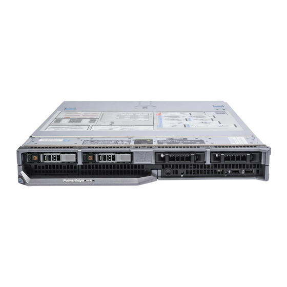
About your Dell PowerEdge M830 (for PowerEdge VRTX) The Dell PowerEdge M830 is a full-height server module that is configured for the PowerEdge VRTX enclosure. It supports up to four processors based on the Intel Xeon E5-4600 v3 family, up to 48 DIMMs, up to four hard drives/SSDs and twelve SSDs. - Page 9 The USB management port can function USB port as a regular USB port or provide access to the iDRAC features. For more information, see the iDRAC User’s Guide at dell.com/ esmmanuals. Management indicator The management indicator lights when the iDRAC controls the USB1 port for management functions.
-
Page 10: Using Usb Diskette Or Usb Dvd/Cd Drives
Using USB diskette or USB DVD/CD drives The server module has USB ports on the front which allow you to connect a USB diskette drive, USB flash drive, USB DVD/CD drive, keyboard, or mouse. The USB drives can be used to configure the server module. -
Page 11: Idrac Direct Led Indicator Codes
Drive-Status Indicator Pattern Condition Identifying drive or preparing for removal Blinks green two times per second Drive ready for insertion or removal NOTE: The drive status indicator remains off until all drives are initialized after system power is applied. Drives are not ready for insertion or removal during this time. -
Page 12: Documentation Matrix
Getting Started With Your System specifications Install the operating system Operating system documentation at dell.com/ operatingsystemmanuals Get an overview of the Dell Systems Management Dell OpenManage Systems Management Overview offerings Guide at dell.com/openmanagemanuals Configure and log in to iDRAC, set up managed... -
Page 13: Quick Resource Locator
Use the Quick Resource Locator (QRL) to get immediate access to system information and how-to videos. This can be done by visiting dell.com/QRL or by using your smartphone and a model specific Quick Resource (QR) code located on your Dell PowerEdge system. To try out the QR code, scan the following image. -
Page 14: Performing Initial System Configuration
• The enclosure Chassis Management Controller (CMC), after the server module iDRAC is configured on the CMC. For more information, see the CMC User’s Guide at dell.com/ esmmanuals. Setting up and configuring the iDRAC IP address You can set up the iDRAC IP address using one of the following interfaces: •... -
Page 15: Logging In To Idrac
Web browsers. For more information, see the iDRAC User’s Guide at dell.com/esmmanuals. You can also remotely monitor and manage the server modules from a single workstation, using the Dell OpenManage Server Administrator (OMSA) software and OpenManage Essentials (OME) systems management console. - Page 16 NOTE: If you do not have the Service Tag, select Automatically detect my Service Tag for me to allow the system to automatically detect your Service Tag, or select Choose from a list of all Dell products to select your product from the Product Selection page. Click Get drivers and downloads.
-
Page 17: Pre-Operating System Management Applications
Your system has the following pre-operating system management applications: • System Setup • Boot Manager • Dell Lifecycle Controller Navigation keys The navigation keys can help you quickly access the pre-operating system management applications. Description <Page Up> Moves to the previous screen. -
Page 18: Entering System Setup
The iDRAC Settings utility is an interface to set up and configure the iDRAC parameters by using UEFI. You can enable or disable various iDRAC parameters by using the iDRAC Settings utility. For more information about this utility, see the Integrated Dell Remote Access Controller User’s Guide at dell.com/esmmanuals. Device Settings Enables you to configure device settings. -
Page 19: System Information Screen
Menu Item Description Integrated Devices Displays options to enable or disable integrated device controllers and ports and specify related features and options. Serial Communication Displays options to enable or disable the serial ports and specify related features and options. System Profile Settings Displays options to change the processor power management settings, memory frequency, and so on. -
Page 20: Processor Settings Screen
Specifies the memory operating mode. The options available are Optimizer Mode, Advanced ECC Mode, Mirror Mode, Spare Mode, Spare with Advanced ECC Mode, and Dell Fault Resilient Mode. By default, the Memory Operating Mode option is set to Optimizer Mode. -
Page 21: Sata Settings Screen
X2Apic Mode Enables or disables the X2Apic mode. Dell Controlled Turbo NOTE: Depending on the number of installed CPUs, there may be up to four processor listings. Controls the turbo engagement. Enable this option only when System Profile is set to Performance. - Page 22 Menu Item Description Embedded SATA Enables the embedded SATA to be set to Off, ATA, AHCI, or RAID modes. By default, the Embedded SATA option is set to AHCI. Security Freeze Lock Sends Security Freeze Lock command to the Embedded SATA drives during POST.
- Page 23 Menu Item Description Port E Sets the drive type of the selected device. For Embedded SATA settings in ATA mode, set this field to Auto to enable BIOS support. Set it to OFF to turn off BIOS support. For AHCI mode or RAID mode, BIOS always enables support. Model Displays the drive model of the selected device.
-
Page 24: Boot Settings Screen
Menu Item Description Capacity Displays the total capacity of the hard drive. The field is undefined for removable media devices such as optical drives. Port J Sets the drive type of the selected device. For Embedded SATA settings in ATA mode, set this field to Auto to enable BIOS support. Set it to OFF to turn off BIOS support. -
Page 25: Integrated Devices Screen
Menu Item Description PXE Device n (n = 1 to 4) Enables or disables the device. When enabled, a UEFI boot option is created for the device. PXE Device n Settings (n = 1 Allows you to control the configuration of the PXE device. to 4) Integrated Devices screen Integrated Devices screen allows you to view and configure the settings of all integrated devices... -
Page 26: Serial Communication Screen
Menu Item Description Memory Mapped I/O above Allows you to enable support for PCIe devices that require large amounts of memory. By default, the option is set to Enabled. Slot Disablement Allows you to enable or disable available PCIe slots on your system. The Slot Disablement feature controls the configuration of PCIe cards installed in the specified slot. -
Page 27: System Profile Settings Screen
You can only change the rest of the options if the mode is set to Custom. By default, the System Profile option is set to Performance Per Watt Optimized (DAPC). DAPC is Dell Active Power Controller. NOTE: The following parameters are available only when the System Profile is set to Custom. -
Page 28: System Security Settings Screen
Menu Item Description Energy Efficient Policy Enables you to select the Energy Efficient Policy. The CPU uses the setting to manipulate the internal behavior of the processor and determines whether to target higher performance or better power savings. Number of Turbo Boot NOTE: If there are two processors installed in the system, you see an Enabled Cores for Processor entry for Number of Turbo Boost Enabled Cores for Processor 2. - Page 29 Menu Item Description TPM Command CAUTION: Clearing the TPM results in the loss of all keys in the TPM. The loss of TPM keys may affect booting to the operating system. Allows you to clear all the contents of the TPM. By default, the TPM Clear option is set to No.
-
Page 30: Miscellaneous Settings Screen
Miscellaneous Settings screen You can use the Miscellaneous Settings screen to perform specific functions such as updating the asset tag, and changing the system date and time. To view the Miscellaneous Settings screen, click System Setup Main Menu → System BIOS → Miscellaneous Settings. -
Page 31: About Boot Manager
Diagnostics and UEFI shell. About Dell Lifecycle Controller Dell Lifecycle Controller allows you to perform tasks such as configuring BIOS and hardware settings, deploying an operating system, updating drivers, changing RAID settings, and saving hardware profiles. For more information about Dell Lifecycle Controller, see the documentation at dell.com/esmmanuals. -
Page 32: Choosing The System Boot Mode
NOTE: Operating systems must be UEFI-compatible to be installed from the UEFI boot mode. DOS and 32-bit operating systems do not support UEFI and can only be installed from the BIOS boot mode. NOTE: For the latest information on supported operating systems, go to dell.com/ossupport. Assigning a system or setup password Prerequisites NOTE: The password jumper enables or disables the System Password and Setup Password features. -
Page 33: Using Your System Password To Secure Your System
• The password can contain the numbers 0 through 9. • Only the following special characters are allowed: space, (”), (+), (,), (-), (.), (/), (;), ([), (\), (]), (`). A message prompts you to re-enter the system password. Re-enter the system password and click OK. Select Setup Password, enter your system password and press Enter or Tab. -
Page 34: Operating With A Setup Password Enabled
NIC • Enable or disable IPMI over LAN • Enable a LAN Platform Event Trap (PET) destination • Attach or detach the Virtual Media devices For more information on using iDRAC, see the iDRAC User's Guide, at dell.com/esmmanuals. -
Page 35: Entering The Idrac Settings Utility
Entering the iDRAC Settings utility Turn on or restart the managed system. Press <F2> during Power-on Self-test (POST). In the System Setup Main Menu page, click iDRAC Settings. The iDRAC Settings page is displayed. -
Page 36: Installing Server Module Components
Damage due to servicing that is not authorized by Dell is not covered by your warranty. Read and follow the safety instructions that came with the product. -
Page 37: Recommended Tools
Damage due to servicing that is not authorized by Dell is not covered by your warranty. Read and follow the safety instructions that came with the product. - Page 38 Ensure that you read the Safety instructions. If installed, remove the front bezel from the PowerEdge VRTX enclosure. Turn off the server module using the operating system commands or the CMC, and ensure that the server module is powered off. When a server module is powered off, its front-panel power indicator is off.
-
Page 39: Installing A Server Module
Damage due to servicing that is not authorized by Dell is not covered by your warranty. Read and follow the safety instructions that came with the product. - Page 40 Steps Press the release buttons and slide the cover toward the back of the server module. Lift the cover away from the server module. Figure 6. Removing and installing the system cover system cover release button (2) I/O connector cover (2) alignment guides on the system cover and the chassis Next steps...
-
Page 41: Installing The System Cover
Damage due to servicing that is not authorized by Dell is not covered by your warranty. Read and follow the safety instructions that came with the product. -
Page 42: Inside The Server Module
Inside the server module Figure 7. Inside the server module PCIe mezzanine card connectors for card 1 restore Serial Peripheral Interface (rSPI) card and card 2 PCIe mezzanine card connectors for card 3 Network Daughter Card (NDC) and card 4 memory module (42) processor 2 cooling shroud... -
Page 43: Cooling Shroud
Damage due to servicing that is not authorized by Dell is not covered by your warranty. Read and follow the safety instructions that came with the product. -
Page 44: Installing The Cooling Shroud
Damage due to servicing that is not authorized by Dell is not covered by your warranty. Read and follow the safety instructions that came with the product. -
Page 45: Installing A Processor Blank And Dimm Blank
Damage due to servicing that is not authorized by Dell is not covered by your warranty. Read and follow the safety instructions that came with the product. -
Page 46: System Memory
Steps Align the standoffs on the processor blank and DIMM blank with the heat sink retention sockets on the processor socket. Lower the processor blank and DIMM blank onto the system until the standoffs on the processor blank and DIMM blank engage with the heat sink retention sockets. Next steps Follow the procedure listed in After working inside your... - Page 47 Figure 10. Memory socket locations Memory channels are organized as follows: Processor 1 channel 0: memory sockets A1, A5, and A9 channel 1: memory sockets A2, A6, and A10 channel 2: memory sockets A3, A7, and A11 channel 3: memory sockets A4, A8, and A12 Processor 2 channel 0: memory sockets B1, B5, and B9 channel 1: memory sockets B2, B6, and B10...
-
Page 48: General Memory Module Installation Guidelines
channel 3: memory sockets B4, B8, and B12 Processor 3 channel 0: memory sockets C1, C5, and C9 channel 1: memory sockets C2, C6, and C10 channel 2: memory sockets C3, C7, and C11 channel 3: memory sockets C4, C8, and C12 Processor 4 channel 0: memory sockets D1, D5, and D9 channel 1: memory sockets D2, D6, and D10... -
Page 49: Mode-Specific Guidelines
dual-rank DIMMs in the sockets with white release tabs and single-rank DIMMs in the sockets with black release tabs. • In a dual- or four-processor configuration, the memory configuration for each processor must be identical. For example, if you populate socket A1 for processor 1, then you must populate socket B1 for processor 2, and so on. -
Page 50: Removing Memory Modules
Damage due to servicing that is not authorized by Dell is not covered by your warranty. Read and follow the safety instructions that came with the product. -
Page 51: Installing Memory Modules
Damage due to servicing that is not authorized by Dell is not covered by your warranty. Read and follow the safety instructions that came with the product. -
Page 52: Sample Memory Configurations
NOTE: You must remove a memory module to upgrade a memory module or replace a faulty memory module. Ensure that you read the Safety instructions. Follow the procedure listed in Before working inside your system. If installed, remove the memory module or the memory-module blank. WARNING: The memory modules are hot to touch for some time after the system has been powered down. - Page 53 Table 2. Memory configurations – two processors System capacity DIMM size (in Number of Organization and DIMM slot population (in GB) DIMMs speed 1R x8, 2133 MT/s A1, A2, A3, A4, B1, B2, B3, 1R x8, 2133 MT/s A1, A2, A3, A4, A5, A6, A7, A8, B1, B2, B3, B4, B5, B6, B7, B8 2R x8, 2133 MT/s...
- Page 54 System capacity DIMM size (in Number of Organization and DIMM slot population (in GB) DIMMs speed 2R x4, 1866 MT/s A1, A2, A3, A4, A5, A6, A7, A8, A9, A10, A11, A12, B1, B2, B3, B4, B5, B6, B7, B8, B9, B10, B11, B12 4R, x4, 2133 MT/s A1, A2, A3, A4, A5, A6, A7,...
-
Page 55: Pcie Mezzanine Cards
D9, D10, D11, D12 PCIe mezzanine cards The server module supports Dell PCIe mezzanine cards. x8 PCIe Gen 2 cards are supported. No other mezzanine cards, such as Ethernet, Fibre Channel, or InfiniBand are supported on server modules configured for the VRTX enclosure. -
Page 56: Removing A Pcie Mezzanine Card
Damage due to servicing that is not authorized by Dell is not covered by your warranty. Read and follow the safety instructions that came with the product. -
Page 57: Installing A Pcie Mezzanine Card
Damage due to servicing that is not authorized by Dell is not covered by your warranty. Read and follow the safety instructions that came with the product. -
Page 58: Pcie Mezzanine Card Support Bracket
Damage due to servicing that is not authorized by Dell is not covered by your warranty. Read and follow the safety instructions that came with the product. -
Page 59: Installing The Pcie Mezzanine Card Support Bracket
Damage due to servicing that is not authorized by Dell is not covered by your warranty. Read and follow the safety instructions that came with the product. -
Page 60: Idsdm Card (Optional)
Damage due to servicing that is not authorized by Dell is not covered by your warranty. Read and follow the safety instructions that came with the product. -
Page 61: Internal Usb Key
Figure 14. Replacing an SD card IDSDM card SD card upper card slot (SD 2) lower card slot (SD 1) Next steps Follow the procedure listed in After working inside your system. Enter the System Setup and ensure that the Internal SD Card Port and Internal SD Card Redundancy modes are enabled. - Page 62 Damage due to servicing that is not authorized by Dell is not covered by your warranty. Read and follow the safety instructions that came with the product.
-
Page 63: Removing The Idsdm Card
Damage due to servicing that is not authorized by Dell is not covered by your warranty. Read and follow the safety instructions that came with the product. -
Page 64: Installing The Idsdm Card
Damage due to servicing that is not authorized by Dell is not covered by your warranty. Read and follow the safety instructions that came with the product. -
Page 65: Rspi Card (Optional)
Damage due to servicing that is not authorized by Dell is not covered by your warranty. Read and follow the safety instructions that came with the product. -
Page 66: Installing The Rspi Card
Damage due to servicing that is not authorized by Dell is not covered by your warranty. Read and follow the safety instructions that came with the product. -
Page 67: Sd Vflash Card
Damage due to servicing that is not authorized by Dell is not covered by your warranty. Read and follow the safety instructions that came with the product. -
Page 68: Network Daughter Card
Damage due to servicing that is not authorized by Dell is not covered by your warranty. Read and follow the safety instructions that came with the product. - Page 69 Ensure that you read the Safety instructions. Follow the procedure listed in Before working inside your system. Keep the #2 Phillips screwdriver ready. Remove the PCIe mezzanine card. Steps Remove the two screws that secure the Network Daughter Card (NDC) to the system board. CAUTION: To prevent damage to the NDC, hold the card only by its edges.
-
Page 70: Installing The Network Daughter Card
Damage due to servicing that is not authorized by Dell is not covered by your warranty. Read and follow the safety instructions that came with the product. -
Page 71: Removing A Heat Sink
Damage due to servicing that is not authorized by Dell is not covered by your warranty. Read and follow the safety instructions that came with the product. -
Page 72: Removing A Processor
Damage due to servicing that is not authorized by Dell is not covered by your warranty. Read and follow the safety instructions that came with the product. - Page 73 Ensure that you read the Safety instructions. Follow the procedure listed in Before working inside your system. Remove the cooling shroud. Remove the heat sink. If installed, remove the processor/DIMM blank. Use a clean, lint-free cloth to remove any thermal grease from the surface of the processor shield. CAUTION: The processor is held in its socket under strong pressure.
- Page 74 Figure 22. Removing and installing a processor socket-release lever 1 pin-1 corner of the processor processor slot (4) processor shield socket-release lever 2 processor socket tab (4) Next steps Replace the processor. Install the heat sink. Related Links Removing the cooling shroud Removing a heat sink Installing a processor Installing a heat sink...
-
Page 75: Installing A Processor
Damage due to servicing that is not authorized by Dell is not covered by your warranty. Read and follow the safety instructions that came with the product. -
Page 76: Installing A Heat Sink
Damage due to servicing that is not authorized by Dell is not covered by your warranty. Read and follow the safety instructions that came with the product. - Page 77 Figure 23. Applying thermal grease on the top of the processor processor thermal grease thermal grease syringe Place the heat sink onto the processor. Tighten one of the four screws to secure the heat sink to the system board. Tighten the screw diagonally opposite to the first screw you tightened. NOTE: Do not over-tighten the heat sink retention screws when installing the heat sink.
-
Page 78: Hard Drives/Ssds
Hard drives/SSDs Your system supports up to four 2.5 inch SAS/SATA/PCIe SSDs or SAS /SATA hard drives and twelve 1.8 inch SAS SSDs. The hard drives/SSDs are supplied in special hot-swappable drive carriers that fit in the drive bays and these drives connect to the system board through the hard-drive/SSD backplane board. NOTE: Mixing of SSD/SAS/SATA hard drives is not supported. -
Page 79: Hard Drive/Ssd Installation Guidelines
Damage due to servicing that is not authorized by Dell is not covered by your warranty. Read and follow the safety instructions that came with the product. -
Page 80: Installing A Hard Drive/Ssd
Figure 27. Removing and installing a hard drive/SSD release button hard drive/SSD connector (on backplane) hard drive/SSD hard drive/SSD carrier handle Next steps If you are removing a hard drive/SSD permanently, install the hard drive/SSD blank. If you are installing a new hard drive/SSD, see Installing a hard drive/SSD. -
Page 81: Removing A Hard Drive/Ssd Blank
Damage due to servicing that is not authorized by Dell is not covered by your warranty. Read and follow the safety instructions that came with the product. -
Page 82: Installing A Hard Drive/Ssd Blank
Figure 29. Removing and installing a 1.8 inch SSD blank SSD blank release latch Next steps Install the hard drive/SSD. See Installing a hard drive/SSD. Installing a hard drive/SSD blank Prerequisites Ensure that you read the Safety instructions. Remove a hard drive/SSD. See Removing a hard drive/SSD. -
Page 83: Removing A 2.5 Inch Hard Drive/Ssd From A 2.5 Inch Hard Drive/Ssd Carrier
Damage due to servicing that is not authorized by Dell is not covered by your warranty. Read and follow the safety instructions that came with the product. -
Page 84: Installing A 2.5 Inch Hard Drive/Ssd In A 2.5 Inch Hard Drive/Ssd Carrier
Damage due to servicing that is not authorized by Dell is not covered by your warranty. Read and follow the safety instructions that came with the product. -
Page 85: Installing A 1.8 Inch Ssd In A 1.8 Inch Ssd Carrier
Damage due to servicing that is not authorized by Dell is not covered by your warranty. Read and follow the safety instructions that came with the product. -
Page 86: Hard Drive/Ssd Cage
Damage due to servicing that is not authorized by Dell is not covered by your warranty. Read and follow the safety instructions that came with the product. -
Page 87: Installing A Hard Drive/Ssd Cage
Damage due to servicing that is not authorized by Dell is not covered by your warranty. Read and follow the safety instructions that came with the product. -
Page 88: Hard Drive/Ssd Backplane
Ensure that you read the Safety instructions. Keep the #1 Phillips screwdriver ready. Remove the hard drive/SSD cage. NOTE: You must remove the hard drive/SSD cage to replace a faulty hard drive/SSD cage or service other components inside the system. Steps Align the screw holes on the hard drive/SSD cage with the screw holes on the chassis. -
Page 89: Removing A 2.5 Inch (X4) Sas Hard Drive/Ssd Backplane
Damage due to servicing that is not authorized by Dell is not covered by your warranty. Read and follow the safety instructions that came with the product. - Page 90 Remove the hard drive(s)/SSD(s). Steps Press the release latches, lift the backplane until the guide pins on the hard drive/SSD cage disengage from the guides on the hard drive/SSD backplane. Remove the hard drive/SSD cage. See Removing a hard drive/SSD cage.
-
Page 91: Installing A 2.5 Inch (X4) Sas Hard Drive/Ssd Backplane
Damage due to servicing that is not authorized by Dell is not covered by your warranty. Read and follow the safety instructions that came with the product. - Page 92 Follow the procedure listed in Before working inside your system. Keep the #2 Phillips screwdriver ready. CAUTION: To prevent damage to the hard drives/SSDs and the hard drive/SSD backplane, you must remove the hard drives/SSDs from the server module before removing the hard drive/SSD backplane.
-
Page 93: Installing A 2.5 Inch (X4) Sata Hard Drive/Ssd Backplane
Damage due to servicing that is not authorized by Dell is not covered by your warranty. Read and follow the safety instructions that came with the product. -
Page 94: Removing A 2.5 Inch (X2) Sata Hard Drive/Ssd Plus 2.5 Inch (X2) Pcie Ssd Backplane
Damage due to servicing that is not authorized by Dell is not covered by your warranty. Read and follow the safety instructions that came with the product. - Page 95 Figure 35. Removing and installing a 2.5 inch (x2) SATA hard drive/SSD plus 2.5 inch (x2) PCIe SSD backplane hard drive/SSD backplane release latch (2) guide pin (5) connector on the system board (SATA_BP) hard-drive/SSD backplane cable connector on the system board connector (J_PERC) PCIe SSD backplane cable connector...
-
Page 96: Installing A 2.5 Inch (X2) Sata Hard Drive/Ssd Plus 2.5 Inch (X2) Pcie Ssd Backplane
Damage due to servicing that is not authorized by Dell is not covered by your warranty. Read and follow the safety instructions that came with the product. -
Page 97: Removing A 1.8 Inch (X12) Sas Ssd Backplane
Damage due to servicing that is not authorized by Dell is not covered by your warranty. Read and follow the safety instructions that came with the product. - Page 98 Figure 36. Removing and installing a 1.8 inch (x12) SAS SSD backplane SSD backplane release latch (2) guide pin (6) backplane cable (2) backplane cable connector that connects connector on the system board to the connector on the system board (SATA_BP) connector on the expander card (EXP) backplane cable connector that...
-
Page 99: Installing A 1.8 Inch (X12) Sas Ssd Backplane
Damage due to servicing that is not authorized by Dell is not covered by your warranty. Read and follow the safety instructions that came with the product. -
Page 100: Nvram Backup Battery
Damage due to servicing that is not authorized by Dell is not covered by your warranty. Read and follow the safety instructions that came with the product. -
Page 101: Storage Controller Card
Figure 37. Replacing the NVRAM backup battery negative side of battery connector positive side of battery Next steps If applicable, install the memory module. Install the following: hard drive/SSD cage hard drive/SSD backplane hard drive/SSD Follow the procedure listed in After working inside your system. -
Page 102: Removing The Storage Controller Card
Damage due to servicing that is not authorized by Dell is not covered by your warranty. Read and follow the safety instructions that came with the product. - Page 103 Figure 38. Removing and installing the storage controller card retention screw (2) slot on the storage controller card tab on the storage controller card support standoff (2) bracket Next steps Install the storage controller card. Related Links Installing the storage controller card Removing a server module Removing the system cover Removing a hard drive/SSD cage...
-
Page 104: Installing The Storage Controller Card
Damage due to servicing that is not authorized by Dell is not covered by your warranty. Read and follow the safety instructions that came with the product. -
Page 105: Expander Card
Damage due to servicing that is not authorized by Dell is not covered by your warranty. Read and follow the safety instructions that came with the product. - Page 106 Figure 39. Removing and installing an expander card screw (3) expander-card cable connector that connects to the connector on the system board (J_PERC) expander card cable expander card guide pin (2) Next steps Install the expander card. Related Links Installing an expander card Removing a server module Removing the system cover Removing a hard drive/SSD cage...
-
Page 107: Installing An Expander Card
Damage due to servicing that is not authorized by Dell is not covered by your warranty. Read and follow the safety instructions that came with the product. -
Page 108: System Board
Damage due to servicing that is not authorized by Dell is not covered by your warranty. Read and follow the safety instructions that came with the product. - Page 109 WARNING: The memory modules are hot to touch for some time after the system has been powered down. Allow time for the memory modules to cool before handling them. Handle the memory modules by the card edges and avoid touching the components. Steps Remove the screws on the system board that secure the system board to the chassis.
- Page 110 Item Icon Description #2 Phillips round screw (6) #2 Phillips hex screw (11) Hex bolt screw-5 mm (3) Hex nut screw-6 mm (3) Figure 41. Removing and installing the system board system board Next steps Install the system board. Related Links Installing the system board...
-
Page 111: Installing The System Board
Damage due to servicing that is not authorized by Dell is not covered by your warranty. Read and follow the safety instructions that came with the product. - Page 112 After working inside your system. Import your new or existing iDRAC Enterprise license. For more information, see the iDRAC8 User's Guide at dell.com/esmmanuals. Ensure that you: Use the Easy Restore feature to restore the Service Tag. For more information, see...
-
Page 113: Trusted Platform Module
Damage due to servicing that is not authorized by Dell is not covered by your warranty. Read and follow the safety instructions that came with the product. -
Page 114: Re-Enabling The Tpm For Bitlocker Users
Figure 42. Installing the TPM TPM connector guide pin on the TPM connector plastic bolt slot on the system board Re-enabling the TPM for BitLocker users Initialize the TPM. For more information on initializing the TPM, see http://technet.microsoft.com/en-us/library/ cc753140.aspx. The TPM Status changes to Enabled, Activated. Re-enabling the TPM for TXT users While booting your system, press <F2>... -
Page 115: Troubleshooting Your System
Damage due to servicing that is not authorized by Dell is not covered by your warranty. Read and follow the safety instructions that came with the product. -
Page 116: Troubleshooting Hard Drives
Damage due to servicing that is not authorized by Dell is not covered by your warranty. Read and follow the safety instructions that came with the product. -
Page 117: Troubleshooting An Internal Sd Card
Damage due to servicing that is not authorized by Dell is not covered by your warranty. Read and follow the safety instructions that came with the product. -
Page 118: Troubleshooting The System Board
Damage due to servicing that is not authorized by Dell is not covered by your warranty. Read and follow the safety instructions that came with the product. -
Page 119: System Messages
System messages For a list of event and error messages generated by the system firmware and agents that monitor system components, see the Dell Event and Error Messages Reference Guide at dell.com/esmmanuals. Warning messages A warning message alerts you to a possible problem and prompts you to respond before the system continues a task. -
Page 120: Using System Diagnostics
Using system diagnostics If you experience a problem with your system, run the system diagnostics before contacting Dell for technical assistance. The purpose of running system diagnostics is to test your system hardware without requiring additional equipment or risking data loss. If you are unable to fix the problem yourself, service and support personnel can use the diagnostics results to help you solve the problem. -
Page 121: System Diagnostics Controls
Displays a time-stamped log of the results of all tests run on the system. This is displayed if at least one event description is recorded. For information about embedded system diagnostics, see the Dell Enhanced Pre-boot System Assessment User Guide at dell.com/support/home. -
Page 122: Jumpers And Connectors
Damage due to servicing that is not authorized by Dell is not covered by your warranty. Read and follow the safety instructions that came with the product. -
Page 123: System Board Connectors
System board connectors Figure 43. System board connectors Table 5. System board connectors Item Connector Description MEZZ1_FAB_C1 PCIe mezzanine card connector for the expansion bus MEZZ2_FAB_B1 PCIe mezzanine card connector for the expansion bus VFLASH SD vFlash card connector bNDC Network daughter card connector IDSDM/rSPI IDSDM/rSPI card connector... -
Page 124: Disabling A Forgotten Password
Damage due to servicing that is not authorized by Dell is not covered by your warranty. Read and follow the safety instructions that came with the product. - Page 125 The existing passwords are not disabled (erased) until the system boots with the password jumper on pins 1 and 2. However, before you assign a new system and/or setup password, you must reinstall the password jumper back to pins 2 and 3. NOTE: If you assign a new system and/or setup password with the jumper on pins 1 and 2, the system disables the new password(s) the next time it boots.
-
Page 126: Technical Specifications-Poweredge M830 (For Poweredge Vrtx)
Technical specifications—PowerEdge M830 (for PowerEdge VRTX) Physical Height 39.52 cm (15.56 inch) Width 5.03 cm (1.98 inch) Depth 54.5 cm (21.45 inch) Weight (maximum) 14.5 kg (31.9 lb) Processor Processor type up to four Intel Xeon E5-4600 v3 product family processors Memory Architecture... - Page 127 NVRAM backup battery CR 2032 3.0 V lithium coin cell Environmental specifications NOTE: For additional information about environmental measurements for specific system configurations, see dell.com/environmental_datasheets. Temperature Storage –40°C to 65°C (–40°F to 149°F) Continuous operation (for altitude less than 950 10°C to 35°C (50°F to 95°F) with no direct...
- Page 128 Environmental specifications Relative humidity Storage 5% to 95% RH with 33°C (91°F) maximum dew point. Atmosphere must be non-condensing at all times. Operating 10% to 80% Relative Humidity with 29°C (84.2°F) maximum dew point. Maximum vibration Operating 0.26 G at 5 Hz to 350 Hz (all operation orientations).
- Page 129 Environmental specifications NOTE: Applies to data center environments NOTE: Air entering the data center must only. Air filtration requirements do not have MERV11 or MERV13 filtration. apply to IT equipment designed to be used outside a data center, in environments such as an office or factory floor.
- Page 130 Do not install more than 40 DIMMs • The following do not support expanded operating temperature range: – PCIe SSD – Express flash – LRDIMMs – 130 W or 120 W all core processors – Non Dell-qualified peripheral cards and/or peripheral cards greater than 25 W...
-
Page 131: Getting Help
Code and Service Tag are found on the front of a physical DR Series system by pulling out the information tag. This can also be found on the support tab in the GUI. This information is used by Dell to...
Need help?
Do you have a question about the PowerEdge M830 and is the answer not in the manual?
Questions and answers