AMX NMX-ENC-1100 Instruction Manual
H.264 encoder
Hide thumbs
Also See for NMX-ENC-1100:
- Instruction manual (60 pages) ,
- Quick start manual (2 pages) ,
- Quick start manual (2 pages)
Table of Contents
Advertisement
Quick Links
Download this manual
See also:
Instruction Manual
Advertisement
Table of Contents

Subscribe to Our Youtube Channel
Related Manuals for AMX NMX-ENC-1100


Summary of Contents for AMX NMX-ENC-1100
- Page 1 I n s t r u c t i o n M a n u a l NMX-ENC H.264 Encoder NMX-ENC-1100 NMX-ENC-1105 L a t e s t R e l e a se : 0 2 / 2 0 / 2 0 1 4...
- Page 2 AMX is not responsible for products returned without a valid RMA number. AMX is not liable for any damages caused by its products or for the failure of its products to perform. This includes any lost profits, lost savings, incidental damages, or consequential damages.
-
Page 5: Table Of Contents
Table of Contents Table of Contents Overview ......................1 Specifications ......................1 Minimum Performance Specifications ............... 2 Mounting the Encoder ....................3 Wiring and Device Connections ................5 Overview ........................5 Front Panel Components ..................5 LEDs ..........................5 AUDIO IN ........................6 USB.......................... - Page 6 Table of Contents Accessing the WebConsole..................23 Retrieving the IP Address of the Encoder ..............23 WebConsole Interface .................... 24 Accessing the WebConsole ................... 24 Encoder Controls......................25 Encoding ........................26 Streaming ........................28 Networking ........................29 System Management..................... 30 Updating Firmware .......................
- Page 7 Table of Contents ?VIDSTRM_IP.......................... 38 VIDSTRM_IP ........................... 38 ?VIDSTRM_PORT........................38 VIDSTRM_PORT ........................38 ?VIDSTRM_MC_EN......................... 38 VIDSTRM_MC_EN ........................38 ?VIDSTRM_MC_IP ........................39 VIDSTRM_MC_IP ........................39 ?VIDSTRM_MC_PORT ......................39 VIDSTRM_MC_PORT ......................39 ?VIDSTRM_MC_TTL........................ 39 VIDSTRM_MC_TTL........................39 ?VIDSTRM_STATUS ........................ 39 Status Commands......................40 ?DISABLE_SWITCH.........................
- Page 8 Table of Contents Instruction Manual - NMX-ENC 2.64 Encoder...
-
Page 9: Overview
PCs, cameras, and set-top boxes. The encoder can stream either unicast and multicast streams. The NMX-ENC is available in two different versions: NMX-ENC-1100 (FG3201-01) and NMX-ENC-1105 (FG3201-02). The NMX-ENC-1105 has the same features as the NMX-ENC-1100 and adds SDI input and pass-thru ports on its rear panel. -
Page 10: Minimum Performance Specifications
Included Accessories: • 1 Power Supply, 4.4A, 13.5VDC, 3.5mm retained Phoenix connector (FG423-46) • 1 NMX-ENC-1100/1105 H.264 Encoder Quick Start Guide (93-3201-01) Optional Accessories: • CC-DVI-5BNCM DVI to 5 BNC adapter cable (FG10-2170-08) • CC-DVI-RCA3M DVI to 3 Male RCA adapter cable for component and composite connections (FG10-2170-09) •... -
Page 11: Mounting The Encoder
Overview Mounting the Encoder You can mount the encoder in a rack by using an NMX-VRK V-Style Rack Shelf (FG3201-60). In addition to the encoder, you can also use wire ties to mount the encoder’s power supply on the rack shelf. The encoder also has rubber feet you can attach to the bottom of the unit for table-top mounting. - Page 12 Overview Instruction Manual - NMX-ENC H.264 Encoder...
-
Page 13: Wiring And Device Connections
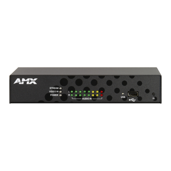
Wiring and Device Connections Wiring and Device Connections Overview This section describes the front and rear panel components for the NMX-ENC-1100 and NMX-ENC-1105. Wiring information for port connectors is listed in each connector’s corresponding section. Front Panel Components The following section lists the components on the front panel of the NMX-ENC encoder. -
Page 14: Audio In
Wiring and Device Connections Consult the following table for the meaning of each LED indicator: LED States Green Blinking Green Red Blinking Red STREAM Not streaming Streaming in Streaming active The streaming progress and there are one engine has or more streaming stopped. - Page 15 Wiring and Device Connections The front panel features an ID pushbutton which allows you to retrieve the IP address and other configuration information for the encoder. You can retrieve this information by inserting a USB drive into the encoder and pressing the ID pushbutton.
-
Page 16: Rear Panel Components
(for video (for video input) output) FIG. 8 NMX-ENC-1100 (rear panel) FIG. 9 displays the rear panel of the NMX-ENC-1105. FIG. 9 NMX-ENC-1105 (rear panel) NMX-ENC-1105 model encoders feature two SDI connectors for video input/output. The SDI input can receive HDMI non-HDCP video with 2 channel LPCM audio at 48 kHz sampling frequency. -
Page 17: Multi Format Video Inputs
Wiring and Device Connections MULTI FORMAT VIDEO INPUTS The encoder features one DVI connector for video input. There are several options for connecting audio and video sources to the encoder. The multi-format video input source can accept DVI Video sources directly with audio connected to ... -
Page 18: Audio
Wiring and Device Connections AUDIO The encoder features two audio ports for receiving and delivering audio. Audio received through the audio INPUT port will be output through the audio PASS THRU port. The audio ports on the encoder are as follows: 1 3.5mm mini-phono connector for audio input (INPUT) ... -
Page 19: Keypad
Wiring and Device Connections KEYPAD The rear panel features one 3-pin 3.5mm Phoenix connector for RS-232 ports for controlling the encoder by keypad or ControlPad. This connector is reserved for future use. The pin-outs for this port are as follows: Pin 1: GND (G) ... -
Page 20: Usb
Wiring and Device Connections The rear panel features one Type-A USB connector. This port is reserved for future use. FIG. 17 displays the USB port. FIG. 17 USB port LAN 10/100 The encoder features four RJ-45 LAN ports for connecting to a network, digital media switcher, presentation switcher, or video distribution device via Cat5 cabling. -
Page 21: Pwr
Wiring and Device Connections Power to the encoder is provided via a 2-pin 3.5mm locking Phoenix connector. Use the provided power supply with the power connector. See the procedures below if you prefer to use a different power supply. FIG. 21 displays the power connector. - Page 22 Wiring and Device Connections Instruction Manual - NMX-ENC H.264 Encoder...
-
Page 23: Cable Details And Pinout Information
Cable Details and Pinout Information Cable Details and Pinout Information Overview The DVI-I Input connector on the rear panel is used to connect video source input devices to the encoder (FIG. 23). The encoder routes video from connected source input devices to the connected output device. Each connector supports DVI as well as VGA, S-Video, Composite, and Component inputs. -
Page 24: Dvi-D Male To Dvi-D Male Single-Link Cable
Cable Details and Pinout Information DVI-D Male to DVI-D Male Single-Link Cable Cable to be composed of the following: Four UL20276 (28AWG twisted pair + drain wire + aluminum foil/mylar shield) for TMDS signals and shields Five UL1589 (28AWG) for DDC_CLK, DDC_DATA, Hot_Plug_Detect, +5VDC, and GROUND ... -
Page 25: Dvi-A Male To 5-Bnc Male Cable
Five 75ohm 28 AWG mini-coax cables for the Red, Green, Blue, VSync, and HSync signals and returns EMI shield metal can on DVI connector Note: This cable type corresponds to the CC-DVI-5BNCM DVI-to-Component cable (FG10-2170-08), available from AMX. DVI-to-5-BNC Cable Pinout Information The following table lists DVI--to-5-BNC cable pinouts: DVI-to-5-BNC Cable Pinout Information DVI-A... -
Page 26: Dvi-A Male To Triple Rca Male Cable
EMI shield metal can on DVI connector Note: This cable type corresponds to the CC-DVI-RCA3M DVI-to-Component/Composite cable (FG10-2170-09), available from AMX. DVI-to-Triple RCA Cable Pinout Information The following table lists the DVI-to-Triple RCA cable pinouts: DVI-to-Triple RCA Cable Pinout Information... -
Page 27: Dvi-A Male To S-Video Male Cable
Two 75ohm 28 AWG mini-coax cables for the Luminance (Y) and Chrominance (C) signals and returns EMI shield metal can on DVI connector Note: This cable corresponds to the CC-DVI-SVID DVI-to-S-Video adapter cable (FG10-2170-10), available from AMX. DVI-to-S-Video Cable Pinout Information The following table lists the DVI-to-S-Video cable pinouts: DVI-to-S-Video Cable Pinout Information... -
Page 28: Dvi-A Male To Hd15 (Vga) Male Adapter
EMI shield metal can on both DVI and HD15 connectors and connected to braid Note: This cable type corresponds to the CC-DVIM-VGAF DVI-to-VGA adapter (FG10-2170-13), available from AMX. DVI-to-VGA Cable Pinout Information The following table lists the DVI-to-VGA cable pinouts:... - Page 29 Cable Details and Pinout Information DVI-to-VGA Cable Pinout Information (Cont.) DVI-A Signal Name Signal Name HD15 (VGA) Notes: Connector Pin TMDS DATA 3 N Pin not populated in DVI-A connector TMDS DATA 3 P Pin not populated in DVI-A connector +5VDC +5VDC 28AWG...
- Page 30 Cable Details and Pinout Information Instruction Manual - NMX-ENC H.264 Encoder...
-
Page 31: Web Configuration
Web Configuration Web Configuration NMX-ENC WebConsole The NMX-ENC WebConsole interface is provided for configuration. Using a standard web browser, enter the IP address of the NMX-ENC for WebControl. The primary page is presented as the NMX-ENC Configuration Manager (unless security is enabled, in which case you will see user login page). The NMX-ENC supports Internet Explorer 9 or better, Firefox (21.0+), and Chrome (27+). -
Page 32: Webconsole Interface
Web Configuration WebConsole Interface The encoder features an on-board WebConsole that allows you to configure the device and make various adjustments to audio/video settings. The WebConsole is accessed via a web browser on a PC that has network access to the encoder. You can access the WebConsole by entering the IP address of the encoder into a web browser. -
Page 33: Encoder Controls
Web Configuration The following sections describe the configuration options and functionality of the NMX-ENC WebConsole. Encoder Controls FIG. 26 displays the encoder controls on the NMX-ENC WebConsole page. These controls are always accessible when navigating through the option tabs on the WebConsole. FIG. -
Page 34: Encoding
Web Configuration Encoding FIG. 27 displays the encoder controls on the NMX-ENC WebConsole page. The encoder controls allow you to configure the audio and video options for the encoder. If a stream is running, it is best to stop the stream before making any changes to it. - Page 35 Web Configuration Encoding Options (Cont.) Video Bitrate (kbps) Enter the target video bit rate for the encoded video. Higher bit rates will result in higher quality encoded video. Enter the bit rate in kilobytes per second (kbps). Press ENTER or click Save to submit the value to the encoder. The default setting is 6000.
-
Page 36: Streaming
Web Configuration Streaming FIG. 28 displays the streaming controls on the NMX-ENC WebConsole page. The streaming controls allow you to set the output format for the stream and whether the stream is unicast or multicast. FIG. 28 Streaming tab The following options are available in this area: Streaming Options Output Format Select an output format from the menu. -
Page 37: Networking
Web Configuration Networking FIG. 29 displays the network controls on the NMX-ENC WebConsole page. The network controls allow you to set up your DHCP or Static network. FIG. 29 Networking tab The following options are available in this area: Networking Options DHCP/Static Click the corresponding option button to select a DHCP or Static communication mode. -
Page 38: System Management
You can view your current firmware in the Firmware Version field on the System Management tab. Follow these steps to upgrade the firmware on the NMX-ENC: Download the latest firmware kit file for the NMX-ENC from www.amx.com. Save or copy the kit file to a hard drive, USB drive, or flash drive accessible by the encoder. -
Page 39: Netlinx
Web Configuration NetLinx FIG. 31 displays the NetLinx controls on the NMX-ENC WebConsole page. The NetLinx controls allow you to set up a connection to a central controller. FIG. 31 NetLinx tab The following options are available in this area: NetLinx Options Master Mode Select the NetLinx Master mode from the menu. - Page 40 Web Configuration Instruction Manual - NMX-ENC H.264 Encoder...
-
Page 41: Programming
SEND_COMMANDS The commands listed in the following sections are for the switcher only. For generic NetLinx commands, see the NetLinx available at www.amx.com. Integrated Controllers WebConsole and Programming Guide The commands derive their input/output port addressing from the target D:P:S. -
Page 42: Audstrm_Codec
Programming Encoding Command (Cont.) ?AUDSTRM_CODEC Syntax: Requests the audio codec SEND_COMMAND <DEV>, "’?AUDSTRM_CODEC’" currently used by the input Example: port. SEND_COMMAND AUDIO_1, "’?AUDSTRM_CODEC’" Returns a COMMAND string of the form: AUDIN_FORMAT-<codec>. ?AUDSTRM_MUTE Request the encoder if the audio stream is muted. Syntax: Requests the audio mute status. -
Page 43: Vidin_Res_Ref
Programming Encoding Commands (Cont.) ?VIDIN_RES_REF Requests to resolution of the video input port addressed by the D:P:S. Note: Queries sent to port 2 will not receive a response from the encoder. All Requests the resolution of queries should be sent to port 1. the video input port. -
Page 44: Vidstrm_Gop
Programming Encoding Commands (Cont.) VIDSTRM_GOP GOP size determines the distance between two full image frames (I-frames) in the encoded video. Sets the GOP size for the Syntax: video stream. SEND_COMMAND <DEV>,"’VIDSTRM_GOP-<gop>’" Variable: gop = 15, 30, 60, 120, 240 Example: SEND_COMMAND VIDEO_INPUT_1,"’VIDSTRM_GOP-60’"... -
Page 45: Streaming Commands
Programming Encoding Commands (Cont.) ?VIDSTRM_RES Requests the resolution for the streamed video output port addressed by the D:P:S. Requests the video Syntax: resolution for the video stream. SEND_COMMAND <DEV>,"’?VIDSTRM_RES’" Example: SEND_COMMAND VIDEO_INPUT_1,"’?VIDSTRM_RES’" Returns a COMMAND string of the form: VIDSTRM_RES-<resolution>. VIDSTRM_RES If you set the resolution to Follow Input, the video is output at the same resolution as the detected input from the video source. -
Page 46: Vidstrm_En
Programming Streaming Commands (Cont.) ?VIDSTRM_EN Syntax: Requests the unicast SEND_COMMAND <DEV>, "’?VIDSTRM_EN’" streaming state. Example: SEND_COMMAND VIDEO_INPUT_1, "’?VIDSTRM_EN’" Returns a COMMAND string of the form: VIDSTRM_EN-<option>. VIDSTRM_EN Syntax: Enables or disables unicast SEND_COMMAND <DEV>, "’VIDSTRM_EN-<option>’" streaming Variables: option =ON or OFF Example: SEND_COMMAND VIDEO_INPUT_1, "’VIDSTRM_EN-ON’"... -
Page 47: Vidstrm_Mc_Ip
Programming Streaming Commands (Cont.) ?VIDSTRM_MC_IP Retrieves the multicast IP used to stream the encoded video and audio. Syntax: Requests the multicast IP address used for streaming. SEND_COMMAND <DEV>, "’?VIDSTRM_MC_IP’" Example: SEND_COMMAND VIDEO_INPUT_1,"’?VIDSTRM_MC_IP’" Returns a COMMAND string of the form: VIDSTRM_MC_IP-<validIP>. VIDSTRM_MC_IP Sets the multicast IP used to stream the encoded video and audio. -
Page 48: Status Commands
Programming Status Commands The following table lists the status commands for the encoder: Status Commands ?DISABLE_SWITCH Retrieves the current state of LAN ports 2-4. Syntax: Requests the state of LAN ports 2-4. SEND_COMMAND <DEV>,"'?DISABLE_SWITCH'" Example: SEND_COMMAND ENCODER_1,"'?DISABLE_SWITCH'" Returns ON or OFF. DISABLE_SWITCH Controls ports 2-4 of the LAN switch. -
Page 49: Vidin_Status
Programming Status Commands (Cont.) ?VIDIN_STATUS Requests the video input status of the video input port addressed by the D:P:S. Note: Queries sent to port 2 will not receive a response from the encoder. All Requests the status of the queries should be sent to port 1. video input port. - Page 50 Programming Instruction Manual - NMX-ENC H.264 Encoder...
-
Page 51: Appendix A - Input Resolutions
Appendix A - Input Resolutions Appendix A - Input Resolutions Available Pixel Display and Refresh Rates The available pixel display and refresh rates for the input devices on the encoder are listed in the following sections. Supported Input Video Resolutions DVI, HDMI, and VGA Supported Input Resolutions Resolution Horizontal... -
Page 52: Component Video Supported Input Resolutions
Appendix A - Input Resolutions Component Video Supported Input Resolutions Component Video Supported Input Resolutions Resolution Horizontal Vertical Refresh Video Name Active Pixels Active (Hz) Standard Pixels 720x480i@60 720x480p@60 59.9 CEA 770.2 SMPTE 293M ITU-R BT.1358 720x576i@50 720x576p@50 ITU-R BT.1358 1280x720p@50 1280 SMPTE 296M... -
Page 53: Appendix B - Output Resolutions
Appendix B - Output Resolutions Appendix B - Output Resolutions Available Scaled Output Resolutions The available scaled resolutions for the output devices on the encoder are listed in the following sections. Important: Currently, the scaled resolution always follows the input resolution. Note: These resolutions are encoder output stream resolutions based on the inputs specified in the tables, and not what is output on the monitor port. -
Page 54: Component Video Supported Output Resolutions
Appendix B - Output Resolutions Component Video Supported Output Resolutions Note: Scaled resolutions will be available in a future release. Currently, the video is output at the same resolution as the detected input from the video source. Component Video Supported Output Resolutions Output Resolution Follow... - Page 55 Appendix B - Output Resolutions Recommended Bit Rates for Output Resolutions (Cont.) Bit Rate kbps Resolution High Medium Lowest Quality Quality Quality 720x576p@50 12288 5120 2048 1024 800x600@60 12288 5120 2048 1024 800x600@72 12288 5120 2048 1024 800x600@75 12288 5120 2048 1024 800x600@85...
- Page 56 Appendix B - Output Resolutions Instruction Manual - NMX-ENC 2.64 Encoder...
- Page 57 Appendix B - Output Resolutions Instruction Manual - NMX-ENC 2.64 Encoder...
- Page 58 - Schedules and registration for any AMX University course - Travel and hotel information - Your individual certification requirements and progress 3000 RESEARCH DRIVE, RICHARDSON, TX 75082 USA • 800.222.0193 • 469.624.8000 • 469-624-7153 fax • 800.932.6993 technical support • www.amx.com...
Need help?
Do you have a question about the NMX-ENC-1100 and is the answer not in the manual?
Questions and answers