Sign In
Upload
Download
Table of Contents
Contents
Add to my manuals
Delete from my manuals
Share
URL of this page:
HTML Link:
Bookmark this page
Add
Manual will be automatically added to "My Manuals"
Print this page
×
Bookmark added
×
Added to my manuals
Manuals
Brands
AMX Manuals
Media Converter
NMX-ENC-N1122
Instruction manual
AMX NMX-ENC-N1122 Instruction Manual
Encoders/decoders digital media distribution & switching solution
Hide thumbs
1
2
3
Table Of Contents
4
5
6
7
8
9
10
11
12
13
14
15
16
17
18
19
20
21
22
23
24
25
26
27
28
29
30
31
32
33
34
35
36
37
38
39
40
41
42
43
44
45
46
47
48
49
50
51
52
53
54
55
56
57
58
59
60
61
62
63
64
page
of
64
Go
/
64
Contents
Table of Contents
Troubleshooting
Bookmarks
Table of Contents
Important Safety Instructions
Table of Contents
Introducing Your New N1000 Series
Product Overview
Common Applications
Features
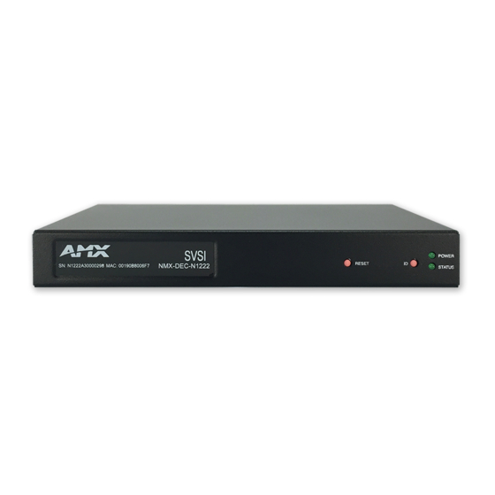
N1122/N1222 Front and Rear Panel Descriptions
N1133/N1233 Front and Rear Panel Descriptions
Installing and Configuring Your AV Equipment
Installation Overview
Mounting Options
Surface and Wall Mounting
Rack Mounting
N1000 Series Stand-Alone Units
N1000 Series Cards
Step-By-Step Installation Instructions
How IP Address Changes Affect Unit Control
Changing IP Addresses
Option 1: Assigning IP Addresses Individually (Using the Settings Page)
Option 2: Assigning IP Addresses to Multiple Units (Using CSV Files)
Switching and Scaling Options
Seamless Switching
Control Options
Primary Control Options
N-Command Controllers
Third-Party Controllers
N-Act | On-Board, Built-In Control
N-Touch | IP Wall Controller
KVM Configuration
Basic Setup
Video/Usb Switching Options
Advanced KVM Setup (with Added Security Features)
Encoder Configuration Options
Settings Page
Encoder Setup Section
Advanced Settings
RS232 Settings
Network Setup Section
Status Section
Change Password
Software Section
Hostplay Page
IR Page
N-Act Page
Serial Page
Security Page
KVM Page
EDID Page
Logs Page
LLDP Page
Decoder Configuration Options
Settings Page
Decoder Setup Section
Advanced Settings
RS232 Settings
Network Setup Section
Status Section
Change Password
Software Section
Audio Downmixer Settings
Crop/Pan/Zoom Page
Localplay Page
IR Page
N-Act Page
Serial Page
Security Page
KVM Page
EDID Page
Logs Page
LLDP Page
Troubleshooting
Series Default Local/Host Play Troubleshooting Screens
Advertisement
Quick Links
1
N1122/N1222 Front and Rear Panel Descriptions
2
How Ip Address Changes Affect Unit Control
3
Settings Page
4
Series Default Local/Host Play Troubleshooting Screens
Download this manual
IN STR U CT IO N MAN U AL
SVS I N 1 0 0 0 M P C S E R I ES E N C O DE RS / D E C O DE RS
D I G I T A L M EDI A D I STR I B U T I O N & S W I TC H I N G S O LU T I O N
NMX-ENC-N1122, NMX-DEC-N1222, NMX-ENC- N1133, AND NMX-DEC-N1233
Table of
Contents
Previous
Page
Next
Page
1
2
3
4
5
Advertisement
Table of Contents
Need help?
Do you have a question about the NMX-ENC-N1122 and is the answer not in the manual?
Ask a question
Questions and answers
Related Manuals for AMX NMX-ENC-N1122
Media Converter AMX NMX-ENC-1105 Quick Start Manual
(2 pages)
Media Converter AMX NMX-ENC-1100 Instruction Manual
(60 pages)
Media Converter AMX NMX-ENC-1100 Instruction Manual
H.264 encoder (58 pages)
Media Converter AMX NMX-ENC-1100 Quick Start Manual
H.264 encoder (2 pages)
Media Converter AMX NMX-ENC-N3121 Instruction Manual
Svsi n3000 series encoders/decoders wan h.264 video over ip digital media distribution & switching solution (72 pages)
Media Converter AMX NMX-ENC-N3132 Instruction Manual
Svsi n3000 series encoders/decoders wan h.264 video over ip digital media distribution & switching solution (72 pages)
Media Converter AMX AND NMX-DEC-N3232 Instruction Manual
Svsi n3000 series encoders/decoders wan h.264 video over ip digital media distribution & switching solution (72 pages)
Media Converter AMX NMX-ENC-N2122, NMX-DEC-N2222, NMX-DEC-N2212, NMX-ENC-N2135, AND NMX-DEC-N2235 Instruction Manual
Svsi n2000 series encoders/decoders digital media distribution & switching solution (70 pages)
Media Converter AMX NMX-DEC-N1222 Instruction Manual
Encoders/decoders digital media distribution & switching solution (64 pages)
Media Converter AMX NMX-DEC-N1233 Instruction Manual
Encoders/decoders digital media distribution & switching solution (64 pages)
Media Converter AMX NMX-ENC-N2151 Quick Start Manual
4k hd series (2 pages)
Media Converter AMX N2412A Instruction Manual
N2400 series. encoder/decoder digital media distribution & switching solution (78 pages)
Media Converter AMX N2422A Instruction Manual
N2400 series. encoder/decoder digital media distribution & switching solution (78 pages)
Media Converter AMX MAX-CSD ENCODER Instruction Manual
Max video encoder (92 pages)
Media Converter AMX AA-53 User Manual
(2 pages)
Media Converter AMX AXB-MIDI Instruction Manual
Axlink bus controllers (20 pages)
This manual is also suitable for:
Nmx-dec-n1222
Nmx-enc-n1133
Nmx-dec-n1233
Table of Contents
Print
Rename the bookmark
Delete bookmark?
Delete from my manuals?
Login
Sign In
OR
Sign in with Facebook
Sign in with Google
Upload manual
Upload from disk
Upload from URL


Need help?
Do you have a question about the NMX-ENC-N1122 and is the answer not in the manual?
Questions and answers