AMX NMX-ENC-1100 Instruction Manual
Hide thumbs
Also See for NMX-ENC-1100:
- Instruction manual (58 pages) ,
- Quick start manual (2 pages) ,
- Quick start manual (2 pages)

Related Manuals for AMX NMX-ENC-1100


Summary of Contents for AMX NMX-ENC-1100
- Page 1 IN STR U CT IO N MAN U AL N M X - E N C H . 2 6 4 E N C O DE R NMX- ENC- 110 0, N MX -EN C- 11 05...
-
Page 2: Important Safety Instructions
COPYRIGHT NOTICE AMX© 2015, all rights reserved. No part of this publication may be reproduced, stored in a retrieval system, or transmitted, in any form or by any means, electronic, mechanical, photocopying, recording, or otherwise, without the prior written permission of AMX. Copyright protection claimed... - Page 3 Anyone performing field maintenance on AMX equipment should use an appropriate ESD field service kit complete with at least a dissipative work mat with a ground cord and a UL listed adjustable wrist strap with another ground cord WARNING: Do Not Open! Risk of Electrical Shock.
-
Page 4: Table Of Contents
Table of Contents Table of Contents Overview ......................8 Specifications ........................8 Minimum Performance Specifications ................9 Mounting the Encoder ....................... 9 Wiring and Device Connections ..............11 Overview ......................... 11 Front Panel Components....................11 LEDs ..............................11 AUDIO IN............................... 12 USB ............................... - Page 5 Table of Contents Accessing the WebConsole ..................... 25 Retrieving the IP Address of the Encoder .................... 25 WebConsole Interface..................... 26 Accessing the WebConsole ........................26 Encoder Controls ..........................27 Event Logs............................. 28 Encoding ............................... 29 Streaming ............................. 31 Recording.............................. 32 Networking ............................
- Page 6 Table of Contents VIDSTRM_RES ..................................43 Streaming Commands .......................... 44 ?STRM_FORMAT..................................44 STRM_FORMAT ..................................44 ?VIDSTRM ....................................44 VIDSTRM ....................................44 ?VIDSTRM_EN ..................................44 VIDSTRM_EN..................................44 ?VIDREC_STATUS .................................. 44 ?VIDREC_STATUS_STR ................................44 ?VIDSTRM_IP..................................45 VIDSTRM_IP................................... 45 ?VIDSTRM_PORT..................................45 VIDSTRM_PORT ..................................45 ?VIDSTRM_MC_EN .................................
- Page 7 Table of Contents Appendix B - Output Resolutions ..............52 Available Scaled Output Resolutions................52 Recommended Bit Rates for Output Resolutions ................. 53 Appendix C - Alarms ..................54 Alarms ..........................54 Alarm Codes ........................55 Streaming Alarms ..........................55 Recording Alarms ..........................56 HTTP Alarms ............................
-
Page 8: Overview
PCs, cameras, and set-top boxes. The encoder can stream either unicast and multicast streams. The NMX-ENC is available in two different versions: NMX-ENC-1100 (FG3201-01) and NMX-ENC-1105 (FG3201-02). The NMX-ENC-1105 has the same features as the NMX-ENC-1100 and adds SDI input and pass-thru ports on its rear panel. NMX-ENC H.264 encoder FIG. -
Page 9: Minimum Performance Specifications
• UL Included Accessories: • 1 Power Supply, 4.4A, 13.5VDC, 3.5mm retained Phoenix connector (FG423-46) • 1 NMX-ENC-1100/1105 H.264 Encoder Quick Start Guide (93-3201-01) Optional Accessories: • CC-DVI-5BNCM DVI to 5 BNC adapter cable (FG10-2170-08) • CC-DVI-RCA3M DVI to 3 Male RCA adapter cable for component and composite connections (FG10- 2170-09) •... - Page 10 Overview Perform these steps to mount the encoder using the NMX-VRK Rack Shelf: Invert the encoder and the rack shelf for ease of installation. Attach the rack shelf to the bottom of the encoder using the #4-40 3/16 inch undercut flat head screws (provided). Insert the screws through the underside of the rack shelf and into the holes on the bottom of the encoder.
-
Page 11: Wiring And Device Connections
Wiring and Device Connections Wiring and Device Connections Overview This section describes the front and rear panel components for the NMX-ENC-1100 and NMX-ENC-1105. Wiring information for port connectors is listed in each connector’s corresponding section. Front Panel Components The following section lists the components on the front panel of the NMX-ENC encoder. -
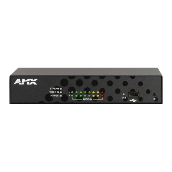
Page 12: Audio In
Wiring and Device Connections AUDIO IN The audio signal strength indicators show the signal strength of the selected audio source. The encoder has separate indicators for the left and right channels. The indicators are updated every half second. FIG. 5 displays the audio signal strength indicators. Audio Signal Strength Indicators FIG. -
Page 13: Rear Panel Components
Wiring and Device Connections Rear Panel Components The following section lists the components on the rear panel of the encoder. FIG. 8 displays the rear panel of the NMX-ENC-1100. LAN (connect Port 1 to network) POWER AUDIO HDMI RS-232 RELAYS... -
Page 14: Multi Format Video Inputs
Wiring and Device Connections MULTI FORMAT VIDEO INPUTS The encoder features one DVI connector for video input. There are several options for connecting audio and video sources to the encoder. The multi-format video input source can accept DVI Video sources directly with audio connected to corresponding audio ... -
Page 15: Video Pass Thru
Wiring and Device Connections VIDEO PASS THRU The encoder features one HDMI connector for video output. The output replicates the video signal currently being encoded when it comes from the multi-format connector or the SDI input connector (NMX-ENC-1105 only). The VIDEO PASS THRU connector enables you to "daisy-chain"... -
Page 16: Indicators
Wiring and Device Connections INDICATORS The rear panel features one 4-pin 3.5mm relay port for connecting up to two independent relay devices. The port features a 2-pin Streaming port (Port 1) and a Recording port (Port 2). Each respective relay port is "ON" when the encoder is streaming. When a relay is "OFF", terminals A and B are open-circuit. -
Page 17: Pwr
Wiring and Device Connections Activity LED (green) Link LED (amber) lights when the LAN cables lights when receiving or are connected and transmitting LAN terminated correctly. data packets. LAN connector/LEDs FIG. 20 Power to the encoder is provided via a 2-pin 3.5mm locking Phoenix connector. Use the provided power supply with the power connector. -
Page 18: Cable Details And Pinout Information
Cable Details and Pinout Information Cable Details and Pinout Information Overview The DVI-I Input connector on the rear panel is used to connect video source input devices to the encoder (FIG. 23). The encoder routes video from connected source input devices to the connected output device. Each connector supports DVI as well as VGA, S-Video, Composite, and Component inputs. -
Page 19: Dvi-D Male To Dvi-D Male Single-Link Cable
Cable Details and Pinout Information DVI-D Male to DVI-D Male Single-Link Cable Cable to be composed of the following: Four UL20276 (28AWG twisted pair + drain wire + aluminum foil/mylar shield) for TMDS signals and shields Five UL1589 (28AWG) for DDC_CLK, DDC_DATA, Hot_Plug_Detect, +5VDC, and GROUND ... -
Page 20: Dvi-A Male To 5-Bnc Male Cable
Five 75ohm 28 AWG mini-coax cables for the Red, Green, Blue, VSync, and HSync signals and returns EMI shield metal can on DVI connector NOTE: This cable type corresponds to the CC-DVI-5BNCM DVI-to-Component cable (FG10-2170-08), available from AMX. DVI-to-5-BNC Cable Pinout Information The following table lists DVI--to-5-BNC cable pinouts: DVI-to-5-BNC Cable Pinout Information... -
Page 21: Dvi-A Male To Triple Rca Male Cable
EMI shield metal can on DVI connector NOTE: This cable type corresponds to the CC-DVI-RCA3M DVI-to-Component/Composite cable (FG10-2170-09), available from AMX. DVI-to-Triple RCA Cable Pinout Information The following table lists the DVI-to-Triple RCA cable pinouts: DVI-to-Triple RCA Cable Pinout Information... -
Page 22: Dvi-A Male To S-Video Male Cable
Two 75ohm 28 AWG mini-coax cables for the Luminance (Y) and Chrominance (C) signals and returns EMI shield metal can on DVI connector NOTE: This cable corresponds to the CC-DVI-SVID DVI-to-S-Video adapter cable (FG10-2170-10), available from AMX. DVI-to-S-Video Cable Pinout Information The following table lists the DVI-to-S-Video cable pinouts: DVI-to-S-Video Cable Pinout Information... -
Page 23: Dvi-A Male To Hd15 (Vga) Male Adapter
EMI shield metal can on both DVI and HD15 connectors and connected to braid NOTE: This cable type corresponds to the CC-DVIM-VGAF DVI-to-VGA adapter (FG10-2170-13), available from AMX. DVI-to-VGA Cable Pinout Information The following table lists the DVI-to-VGA cable pinouts:... - Page 24 Cable Details and Pinout Information DVI-to-VGA Cable Pinout Information (Cont.) DVI-A Signal Name Signal Name HD15 (VGA) Notes: Connector Pin TMDS SHIELD 0/5 Pin not populated in DVI-A connector TMDS DATA 5 N Pin not populated in DVI-A connector TMDS DATA 5 P Pin not populated in DVI-A connector TMDS CLOCK Pin not populated in DVI-A connector...
-
Page 25: Web Configuration
Web Configuration Web Conf iguration NMX-ENC WebConsole The NMX-ENC WebConsole interface is provided for configuration. Using a standard web browser, enter the IP address of the NMX-ENC for WebControl. The primary page is presented as the NMX-ENC Configuration Manager, where you are required to log on. -
Page 26: Webconsole Interface
Web Configuration WebConsole Interface The encoder features an on-board WebConsole that allows you to configure the device and make various adjustments to audio/ video settings. The WebConsole is accessed via a web browser on a PC that has network access to the encoder. You can access the WebConsole by entering the IP address of the encoder into a web browser. -
Page 27: Encoder Controls
Web Configuration The following sections describe the configuration options and functionality of the NMX-ENC WebConsole. Encoder Controls FIG. 26 displays the encoder controls on the NMX-ENC WebConsole page. These controls are always accessible when navigating through the option tabs on the WebConsole. Encoder Controls FIG. -
Page 28: Event Logs
Web Configuration The following table describes the different states of the Streaming controls. Streaming Control States State Description Stopped The stream can be started. Starting The Stream button is disabled and does not allow the user to send multiple stream start/stop commands. Started The Stream button can only be used to stop the currently active stream. -
Page 29: Encoding
Web Configuration Encoding FIG. 28 displays the encoder controls on the NMX-ENC WebConsole page. The encoder controls allow you to configure the audio and video options for the encoder. The web console automatically prevents any changes when the stream is running by graying out all configuration options. - Page 30 Web Configuration Encoding Options (Cont.) Video Profile Select the encoding profile. The profile defines the subset of H.264 encoding techniques that will be used during the encode process. Not all decoders support all profiles; therefore, it is important to select a profile that is supported by all playback devices for a given application.
-
Page 31: Streaming
Web Configuration Streaming FIG. 29 displays the streaming controls on the NMX-ENC WebConsole page. The streaming controls allow you to set the output format for the stream and whether the stream is unicast or multicast. Streaming tab FIG. 29 The following options are available on the Streaming tab: Streaming Options Output Format Select an output format from the menu. -
Page 32: Recording
Web Configuration Recording FIG. 30 displays the recording controls on the NMX-ENC WebConsole page. Recording tab FIG. 30 The following options are available on the Recording tab: Recording Options Default Filename Prefix Enter the prefix you want to use for recording. The encoder appends the prefix with a stamp that identifies the time and date of the recording. - Page 33 Web Configuration Recording Options (Cont.) Enable Store and Forward Check this box to configure an FTP server to which the encoder will automatically upload a recorded file when the recording is complete. Forwarding is only supported through the USB port on the rear panel of the encoder.
-
Page 34: Networking
Web Configuration Networking FIG. 31 displays the network controls on the NMX-ENC WebConsole page. The network controls allow you to set up your DHCP or Static network. Networking tab FIG. 31 The following options are available on the Networking tab: Networking Options DHCP/Static Click the corresponding option button to select a DHCP or Static communication mode. -
Page 35: System
Web Configuration System FIG. 32 displays the system controls on the NMX-ENC WebConsole page. The system controls allow you to update the firmware, reboot, or restore the default settings for the encoder. System Management tab FIG. 32 The following options are available on the System tab: System Options Firmware Version The Firmware area displays the current firmware version. -
Page 36: Updating Firmware
You can view your current firmware in the Firmware Version field on the System Management tab. Follow these steps to upgrade the firmware on the NMX-ENC: Download the latest firmware kit file for the NMX-ENC from www.amx.com. Save or copy the kit file to a hard drive, USB drive, or flash drive accessible by the encoder. -
Page 37: Users
Web Configuration NetLinx Options (Cont.) System No Enter a system number in the provided field. This option is not available if you set the NetLinx Master mode to Auto. Username Enter the username for access to the NetLinx Master, if required by the Master. Password Enter the password for access to the NetLinx Master, if required by the Master. -
Page 38: Programming
The commands listed in the following sections are for the encoder only. For generic NetLinx commands, see the NetLinx Integrated Controllers WebConsole and Programming Guide available at www.amx.com. The commands derive their input/output port addressing from the target D:P:S. ... -
Page 39: Port Functionality Mapping
Programming Level 22 Input Video Status Level Description Level Value Description Valid video signal Unknown format or mismatch format No signal Level 27 Input Video Status Level Description Level Value Description SDI when ?VIDOUT_ASSIGN = 2 HDMI when ?VIDOUT_ASSIGN = 1 Component S-Video Composite... -
Page 40: Encoding Commands
Programming Encoding Commands The following table lists the encoding commands available for the encoder: Encoding Commands ?AUDIN_FORMAT Requests the format of the audio input. Syntax: SEND_COMMAND <DEV>, "’?AUDIN_FORMAT’" Example: SEND_COMMAND AUDIO_1, "’?AUDIN_FORMAT’" Returns a COMMAND string of the form: AUDIN_FORMAT-<options>. AUDIN_FORMAT Specifies the audio input format for port addressed by the D:P:S. -
Page 41: Vidin_Format
Programming Encoding Command (Cont.) ?VIDIN_FORMAT Requests the input format of the video port addressed by the D:P:S. NOTE: Queries sent to port 2 will not receive a response from the encoder. All queries should be sent to port 1. Syntax: SEND_COMMAND <DEV>, "’?VIDIN_FORMAT’"... -
Page 42: Vidstrm_Gop
Programming Encoding Commands (Cont.) VIDSTRM_GOP GOP size determines the distance between two full image frames (I-frames) in the encoded video. Syntax: SEND_COMMAND <DEV>,"’VIDSTRM_GOP-<gop>’" Variable: gop = 15, 30, 60, 120, 240 Example: SEND_COMMAND VIDEO_INPUT_1,"’VIDSTRM_GOP-60’" ?VIDSTRM_PROFILE Requests the selected encoding profile selected for streamed video output port addressed by the D:P:S. Syntax: SEND_COMMAND <DEV>, "’?VIDSTRM_PROFILE’"... -
Page 43: Record Commands
Programming Encoding Commands (Cont.) VIDSTRM_RES If you set the resolution to Follow Input, the video is output at the same resolution as the detected input from the video source. Setting another option scales the video output down by the indicated fraction. See the Available Scaled Output Resolutions section on page 52 for a list of scaled output resolutions. -
Page 44: Streaming Commands
Programming Record Commands (Cont.) ?VIDREC_STATUS Requests the state of recording by the encoder addressed by D:P:S. Syntax: SEND_COMMAND <DEV>,"'?VIDREC_STATUS'" Example: SEND_COMMAND ENCODER_1,"'?VIDREC_STATUS'" Returns a COMMAND string of the form: VIDREC_STATUS-<status>. The following statuses may be reported: STARTING, STARTED, STOPPING, STOPPED, SUSPENDED, and NOT ALLOWED. ?VIDREC_STATUS_STR Requests the recording status string. -
Page 45: Vidstrm_Ip
Programming Streaming Commands (Cont.) ?VIDSTRM_IP Retrieves the unicast IP address used to stream the encoded video and audio. Syntax: SEND_COMMAND <DEV>, "’?VIDSTRM_IP’" Example: SEND_COMMAND VIDEO_INPUT_1, "’?VIDSTRM_IP’" Returns a COMMAND string of the form: VIDSTRM_IP-<validIP>. VIDSTRM_IP Sets the Unicast IP address used to stream the encoded video and audio. Syntax: SEND_COMMAND <DEV>, "’VIDSTRM_IP-<validIP>’"... -
Page 46: Status Commands
Programming Streaming Commands (Cont.) VIDSTRM_MC_PORT Sets the multicast port used to stream the encoded video and audio. Syntax: SEND_COMMAND <DEV>, "’VIDSTRM_MC_PORT-<Port>’" Variables: port = any port number between 1024 and 32768 Example: SEND_COMMAND VIDEO_INPUT_1,"’VIDSTRM_MC_PORT-9000’" ?VIDSTRM_MC_TTL Retrieves the multicast Time to Live (TTL) used to stream the encoded video and audio. Syntax: SEND_COMMAND <DEV>, "'?VIDSTRM_MC_TTL"... -
Page 47: Fwversion
Programming Status Commands (Cont.) ?FWVERSION Requests the firmware version of the encoder. Syntax: SEND_COMMAND <DEV>,"'?FWVERSION'" Example: SEND_COMMAND ENCODER_1,"'?FWVERSION'" Returns a COMMAND string of the form: FWVERSION-<version>. ?LED_CTRL Retrieves the current state of the LEDs. Syntax: SEND_COMMAND <DEV>,"'?LED_CTRL'" Example: SEND_COMMAND ENCODER_1,"'?LED_CTRL'" Returns ON, meaning 10% brightness, or OFF, meaning full brightness. -
Page 48: Accessing The Encoder Via Telnet
Programming Accessing the Encoder via Telnet The NMX-ENC encoders provide a Telnet interface which allows modifications to parameters without using NetLinx code or accessing the WebConsole. You can access the encoder via any Telnet client on the same network as the encoder. Follow these steps to Telnet into the encoder: Open your Telnet client. -
Page 49: Session
Programming Telnet Commands (Cont.) Command Description Internally issues a NetLinx SEND_COMMAND to the encoder. Usage: > sc <port> <SEND_COMMAND> Example: > sc 1 VIDIN_FORMAT-HDMI Sets the video input format for port 1 to HDMI. See the Accessing the Encoder via Telnet section on page 48 for more examples on using the sc command. -
Page 50: Appendix A - Input Resolutions
Appendix A - Input Resolutions Appendix A - Input Resolutions Available Pixel Display and Refresh Rates The available pixel display and refresh rates for the input devices on the encoder are listed in the following sections. Supported Input Video Resolutions DVI, HDMI, and VGA Supported Input Resolutions Resolution Name Horizontal... -
Page 51: Component Video Supported Input Resolutions
Appendix A - Input Resolutions Component Video Supported Input Resolutions Component Video Supported Input Resolutions Resolution Name Horizontal Vertical Active Refresh (Hz) Video Standard Active Pixels Pixels 720x480i@60 720x480p@60 59.9 CEA 770.2 SMPTE 293M ITU-R BT.1358 720x576i@50 720x576p@50 ITU-R BT.1358 1280x720p@50 1280 SMPTE 296M... -
Page 52: Appendix B - Output Resolutions
Appendix B - Output Resolutions Appendix B - Output Resolutions Available Scaled Output Resolutions The available scaled resolutions for the output devices on the encoder are listed below. The NMX-ENC encoder is capable of following the input and producing the same resolution as the input. It can also scale down the input to the resolutions shown in the table below. -
Page 53: Recommended Bit Rates For Output Resolutions
Appendix B - Output Resolutions Recommended Bit Rates for Output Resolutions The following table lists the recommended bit rates you can set for various video output qualities. You can set the video bit rate on the Encoder tab in the NMX-ENC WebConsole (see NMX-ENC WebConsole section on page 25 for more information.) Recommended Bit Rates for Output Resolutions Resolution Bit Rate kbps... -
Page 54: Appendix C - Alarms
Appendix C - Alarms Appendix C - Alarms Alarms This section provides a list of alarm codes, alarm priorities, and descriptions for any alarms that may occur on the encoder. You can view a listing of recent alarms on the encoder by clicking the Event Logs button on the WebConsole (see the Event Logs section on page 28 for more information.) FIG. -
Page 55: Alarm Codes
Appendix C - Alarms Alarm Codes The following sections list the alarm codes for each alarm category. Streaming Alarms The following table list the Streaming alarms. Streaming Alarms Code Priority Text Description Stream suspended duration [x days xx:xx:xx] Some anomaly has suspended streaming: •... -
Page 56: Recording Alarms
Appendix C - Alarms Recording Alarms The following table lists the Recording alarms. Recording Alarms Code Priority Text Description Record terminated due to file I/O Due to file write error or creation error, the current record session was terminated. Recording: <full file name> A full path name of the file being recorded. -
Page 57: System Alarms
Appendix C - Alarms System Alarms The following table lists the System alarms. System Alarms Code Priority Text Description Encoder starting up The encoder has started after a reboot or power cycle. Canceling network config change The ID button was not released at the interval to allow network configuration to be toggled. -
Page 58: Network Alarms
Appendix C - Alarms Network Alarms The following table lists the Network alarms. Network Alarms Code Priority Text Description Port <num> is plugged in Port <num> is connected to a valid network capable device. Port <num> is unplugged Port <num> is connected to a valid network capable device. All Ethernet ports are disconnected None of the ports are connected to a network device. -
Page 59: Ntp Alarms
Appendix C - Alarms NTP Alarms The following table lists the NTP alarms. NTP Alarms Code Priority Text Description NTP active System believes that NTPD is running and working correctly. Cannot Reach NTP Server <server URL> The system was unable to establish a successful NTP communication with the selected NTP server. - Page 60 © 2016 Harman. All rights reserved. NetLinx, AMX, AV FOR AN IT WORLD, and HARMAN, and their respective logos are registered trademarks of Last Revised: HARMAN. Oracle, Java and any other company or brand name referenced may be trademarks/registered trademarks of their respective companies.
Need help?
Do you have a question about the NMX-ENC-1100 and is the answer not in the manual?
Questions and answers