Table of Contents
Advertisement
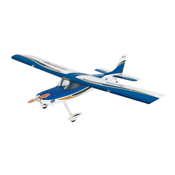
INSTRUCTION MANUAL
SPECIFICATIONS
Wingspan:
90.5 in [ 2300 mm]
Length:
77.25 in [ 1962mm]
2
Wing Area:
1448 in
[93.4 dm
WARRANTY
Great Planes
®
Model Manufacturing Co. guarantees this
kit to be free from defects in both material and workmanship at
the date of purchase. This warranty does not cover any
component parts damaged by use or modification. In no case
shall Great Planes' liability exceed the original cost of
the purchased kit. Further, Great Planes reserves the right to
change or modify this warranty without notice.
In that Great Planes has no control over the final assembly or
material used for final assembly, no liability shall be assumed nor
accepted for any damage resulting from the use by the user of
the final user-assembled product. By the act of using the
user-assembled product, the user accepts all resulting liability.
If the buyer is not prepared to accept the liability
associated with the use of this product, the buyer is
READ THROUGH THIS MANUAL BEFORE STARTING CONSTRUCTION. IT CONTAINS IMPORTANT
INSTRUCTIONS AND WARNINGS CONCERNING THE ASSEMBLY AND USE OF THIS MODEL.
© 2015 Great Planes Model Mfg. A subsidiary of Hobbico,
16.5 – 17.5 lbs
Weight:
[ 7482 – 7935 g]
Wing
26 – 28 oz/ft
2
]
Loading:
[ 79 – 85 g /dm
®
Inc.
Radio:
4 −11 Channel
Engine:
1.8 − 2.0 cu in [30 − 35 cc]
2
2
Electric:
RimFire 1.60 (63-62-250) Brushless
]
advised to return this kit immediately in new and
unused condition to the place of purchase.
To make a warranty claim send the defective part or item to
Hobby Services at the address below:
Hobby Services
3002 N. Apollo Dr. Suite 1
Champaign IL 61822 USA
Include a letter stating your name, return shipping address, as
much contact information as possible (daytime telephone
number, fax number, e-mail address), a detailed description of
the problem and a photocopy of the purchase receipt. Upon
receipt of the package the problem will be evaluated as quickly
as possible.
Champaign, Illinois
(217) 398-8970, Ext 5
airsupport@greatplanes.com
GPMA1675
Advertisement
Table of Contents

Related Manuals for GREAT PLANES Avistar 30cc ARF


Summary of Contents for GREAT PLANES Avistar 30cc ARF
-
Page 1: Instruction Manual
3002 N. Apollo Dr. Suite 1 Champaign IL 61822 USA In that Great Planes has no control over the final assembly or material used for final assembly, no liability shall be assumed nor Include a letter stating your name, return shipping address, as... -
Page 2: Table Of Contents
Continuing with the success of the Avistar line, Great Planes over groups of people. brings you the Avistar 30cc ARF. This is a great fi rst gas powered model. The optional fl aps allow you to add the fl aps SAFETY PRECAUTIONS later if you desire. -
Page 3: Decisions You Must Make
Vacuum the parts and the work area thoroughly after working with fi berglass parts. The radio installation for the Avistar 30cc ARF can be achieved 8. WARNING: If you are building this plane as electric... - Page 4 Electric Motor Installation technology to transmit control signals between your receiver and servos. A single S.Bus cable can carry signals to as (2) 24" Servo extensions (TACM2721) many channels as your transmitter can handle. You no longer (3) 16" Servo extensions (FUTM4145) have to worry about plugging in the wrong servo to the (2) Y-harness (TACM2751) For Flaps and Ailerons wrong channel, because each servo knows what channel it...
-
Page 5: S.bus Quick Start
S.BUS SYSTEM S.Bus Receiver Battery WING Servo Servo Servo Servo Electric Motor Installation (1) S.Bus Servo Hub Cable 300mm (FUTM4195) (1) 16” Servo Extension (FUTM4145) (1) Y-harness for elevator (TACM2751) or (FUTM4135) (1) Heavy Duty on/off switch (FUTM4385) (TACM2760) (1) Charge Receptacle (ERNM3001) (1) 3200mAh LiFe Receiver battery (HCAM6446) Additional Items for Gas Installation (2) 6”... -
Page 6: Additional Items Required
Dubro #813 Fuel Line Barbs (DUBQ0670) Adhesives and Building Supplies This is the list of Adhesives and Building Supplies that are required to fi nish the Avistar 30cc ARF. 1/2 oz. [15g] Thin Pro CA (GPMR6001) Pro 30-minute epoxy (GPMR6047) Pro 6-minute epoxy (GPMR6045) 4. -
Page 7: Optional Supplies And Tools
Defl ection Gauge (GPMR2405) ™ CG Machine (GPMR2400) To locate a hobby dealer, visit the Great Planes web site at Precision Magnetic Prop Balancer (TOPQ5700) www.greatplanes.com. Choose “Where to Buy”. Follow the instructions provided on the page to locate a U.S., Canadian or International dealer. -
Page 8: Kit Contents
KIT CONTENTS 1. Fuselage 8. Main Gear 15. Hatch 2. Cowl 9. Main Wheel Pants 16. Motor Box (see parts list for break down) 3. Left Wing Panel 10. Tail Gear 17. Receiver Tray 4. Right Wing Panel 11. Spinner 18. - Page 9 1. Install a servo lead extension or S.Bus 1100 mm 5. Drill servo screw mounting hole. decoder on the S3305 servo or 6” extension and 1000 mm S.Bus hub on the S.Bus S3070HV servo. 6. Install servo screws. 2. Install grommets and eyelets on all servos. 3.
- Page 10 9. Install the 4-40 threaded clevis. 10. Attach clevis to control horn. 11. Position control horn on aileron. 13. Install the solder clevis. 12. Mount control horn.
-
Page 11: Flap Servo Installation (Optional)
15. Repeat steps 1 – 14 to install the aileron servo in the right wing. Flap Servo Installation (Optional) HOW TO SOLDER Flaps are not necessary to land the Avistar 30cc. However, if you have never fl own with fl aps, the Avistar 30cc is a great plane to learn with. - Page 12 6. Plug the flap servo into the flap channel or the decoder hub into the S.Bus port on your receiver. Switch on your radio system and adjust the flap control so that the travel is at its end point. Install a servo arm on the flap servo so that it is approximately 45 degrees from the centerline of the servo.
-
Page 13: Assemble The Fuselage
12. Trim the covering from over the wing bolt holes. 3. Trim the covering. ASSEMBLE THE FUSELAGE Install the Tail 1. Slide both wing halves onto the wing tube. Slide the wing halves together. 4. Temporarily install the horizontal stabilizer and the vertical fin. -
Page 14: Install The Main Landing Gear
Install the Main Landing Gear A = B If installing the optional fl oats (GPMA1676), skip to Install the Rudder & Elevator Servos 1. Install the 3/16" [4.8mm] axles. 5. Check the alignment of the horizontal stabilizer. The distance from the center of the nose of the fuselage to the tips of the horizontal stabilizer should be equal. -
Page 15: Install The Tail Gear
6. Install the main landing gear on the fuselage. Install the Tail Gear 4. Install the main wheel. 1. Drill a 15/64" [6mm] hole in the bottom of the fuselage. 2. Use 6-minute epoxy to glue the tail gear bearing in the fuselage. - Page 16 4. Slide the tail gear spacer and the tail gear wire support 8. Apply 6-minute epoxy in the hole for the tail gear wire onto the tail gear wire. support. Before the epoxy cures, insert the support in the hole and the tail gear wire in the tail gear bearing. Attach the tail gear bracket to the fuselage with two #2 x 3/8"...
-
Page 17: Install The Optional Trike Gear
Install the Optional Trike Gear (GPMA4568 and GPMA4561) (nose gear not included) 5. Separate the top and bottom of the nylon nose gear bearing. Install the nose gear bearing on the back side of the firewall. Before completely tightening the cap screws, insert 1. -
Page 18: Install The Rudder & Elevator Servos
11. Position a 5mm wheel collar under the nose gear 8. Insert the nose gear wire in the nose gear wheel pant, bearing. Insert the nose gear wire through the wheel, the through a 5mm wheel collar, the nose wheel, a second 5mm bottom nose gear bearing, the steering arm and the top nose wheel collar and the nose gear retainer recess on the inside gear bearing. - Page 19 8. Install a 4-40 threaded clevis on the rudder pushrod. Attach the control horn. 3. Securely glue the receiver/receiver battery tray in the fuselage. 4. Install the receiver and receiver battery. 9. Position the rudder control horn. 5. Install the receiver battery switch and charge recepticle. Connect the receiver battery to the switch and the switch to the receiver.
-
Page 20: Nose Gear Steering (For Optional Nose Gear)
11. Center the rudder and servo arm. Attach a 4-40 solder Nose Gear Steering (for optional nose gear) clevis to the rudder servo horn. Mark, cut and solder the clevis on the rudder pushrod following the same procedure used for the aileron pushrods. 1. -
Page 21: Electric Motor Installation
8. Remove the rudder servo arm, insert the steering pushrod in the pushrod connector and reinstall the servo arm. 5. Insert the pushrod in the outer pushrod tube. 9. Center the nose wheel and tighten the screw. Electric Motor Installation Proceed to Engine and Tank Installation (page 23) if a gas engine will be installed. - Page 22 2. Install the 8-32 blind nuts and secure with CA. 6. Mount the ESC. Connect the wires from the ESC to the motor wires. 3. Use epoxy to glue the motor box together. The blind nuts go to the inside. 7.
-
Page 23: Gas Engine Installation
11. Install the battery tray. 3. If installing one of the DLE engines, glue the three 1/8" (3.2mm) plywood engine standoffs together. Apply a thin 12. Check that the throttle is set to reverse if using a coat of epoxy to fuelproof them. The O.S. GT33 uses the 2" Futaba transmitter. - Page 24 6. Remove the engine and drill 3/16" (4.8 mm) holes through the fi rewall for the throttle and choke. 11. Wrap the ignition battery and ignition module in foam. Install the ignition battery below the tray and the ignition module on top of the tray. If the plane is set up with trike gear, the battery and ignition module may need to be offset to the side.
- Page 25 15. Assemble the throttle pushrod. 21. Snap the pivot ball socket on the throttle pivot ball. Switch on the radio system, and move the throttle stick to full throttle. Rotate the throttle arm to full throttle. 16. Cut the outer pushrod tube 7-1/2" [190 mm] long. 17.
-
Page 26: Choke Control
CHOKE CONTROL Assemble the Fuel Tank The choke can be controlled manually or with a servo. Manual Choke Control 1. Clean both ends of the brass tubes with sandpaper. 1. Assemble the choke pushrod. 2. Solder fuel line barbs onto one end of the brass tubes. 2. -
Page 27: Install The Fuel Tank
Install the Fuel Tank 6. Install the two fuel pickup lines and clunks so they move freely. 1. Install and mark the fuel lines: Vent, Carb and Fill. 7. Loosely install the fuel tank stopper screw. 2. Secure the fuel tank in the fuselage. 8. -
Page 28: Install The Cowl
Install the Cowl For the electric installation, skip to step 2. 3. Drill 5/64" [ 2 mm] pilot holes. Attach the cowl using #4 x 1/2" [12.7mm ] sheet metal screws and #4 fl at washers. 1. Trim the cowl to fi t over the cylinder head and muffl er. 4. -
Page 29: Apply The Decals
3. Position the hatch on the fuselage. 6. Use a T-pin to poke holes along the inside of the outline. 7. Wipe off the marks. Remove the hatch from the fuselage 4. Test fit the windscreen on the hatch. Trim as necessary. and glue the windscreen to the hatch with Canopy Glue. -
Page 30: Get The Model Ready To Fly
4-CHANNEL RADIO SET UP GET THE MODEL READY TO FLY (STANDARD MODE 2) Check the Control Directions RIGHT AILERON RUDDER MOVES UP MOVES LEFT AILERON RIGHT MOVES DOWN FULL ELEVATOR THROTTLE MOVES DOWN 4. Make certain that the control surfaces and the carburetor respond in the correct direction as shown in the diagram. -
Page 31: Install The Propeller
LESS Pushrod Farther Out THROW Pushrod Closer In MORE THROW Pushrod Farther Out Pushrod Closer In 4. Once the throws are set, apply a drop of threadlocker to the threads and tighten the 4-40 nuts against the clevises. Slide the silicone retainers over the clevises. MORE LESS IMPORTANT: Now that you have the throws... -
Page 32: Balance The Model Laterally
3. Install the spinner cone. 2. With the plane ready to fl y, with an empty fuel tank or motor batteries installed, use a Great Planes C.G. Machine or 4. Install the plastic floor. apply narrow (1/16" [2mm]) strips of tape at the front and rear... -
Page 33: Preflight
ENGINE SAFETY PRECAUTIONS 3. Use Great Planes “stick on” weight (GPMQ4485) to Failure to follow these safety precautions may result balance the plane. Place incrementally increasing amounts in severe injury to yourself and others. -
Page 34: Electric Motor Safety Precautions
Keep these items away from the prop: loose clothing, shirt NEVER place the battery or charger on combustible sleeves, ties, scarfs, long hair or loose objects such as materials or leave it unattended during charge or discharge. pencils or screwdrivers that may fall out of shirt or jacket ALWAYS KEEP OUT OF THE REACH OF CHILDREN. -
Page 35: Flying
It is a good idea to have an assistant on the fl ight line with The Avistar 30cc ARF is a great-fl ying model that fl ies smoothly you to keep an eye on other traffi c. Take it easy with the and predictably. -
Page 36: Parts List
model will be able to reach the landing zone (on dead-stick maneuver should be deliberate, not impulsive. A fl ight plan landings it is common to land with no fl aps at all). Without reduces the chances of crashing your model because of engine power, fl aps can unexpectedly reduce the model’s poor planning and impulsive moves.
Need help?
Do you have a question about the Avistar 30cc ARF and is the answer not in the manual?
Questions and answers