GREAT PLANES Extra 330S ARF Instruction Manual
Hide thumbs
Also See for Extra 330S ARF:
- Instruction manual (44 pages) ,
- Instruction manual (28 pages)
Table of Contents
Advertisement
Quick Links
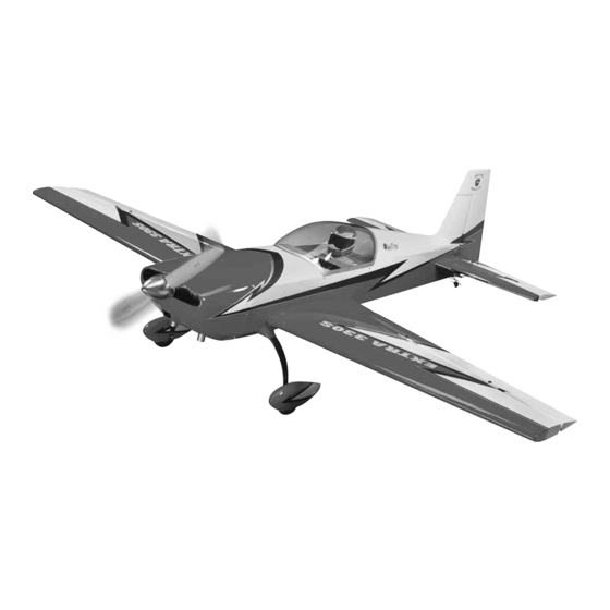
Scale: 38%
Wingspan: 110.5 in [2805mm]
Fuselage Length: 103 in [2595mm]
Wing Area: 2279 sq in [147dm
Weight: 36–38 lb [16330–17235g]
Wing Loading: 36–38 oz/sq ft [111–117g/dm
Engine: 120 – 150cc Spark-Ignition Gas
®
Great Planes
Model Manufacturing Co. guarantees this kit to
be free from defects in both material and workmanship at the date
of purchase. This warranty does not cover any component parts
damaged by use or modifi cation. In no case shall Great Planes'
liability exceed the original cost of the purchased kit. Further,
Great Planes reserves the right to change or modify this warranty
without notice.
In that Great Planes has no control over the fi nal assembly or
material used for fi nal assembly, no liability shall be assumed nor
accepted for any damage resulting from the use by the user of
the fi nal user-assembled product. By the act of using the user-
assembled product, the user accepts all resulting liability.
If the buyer is not prepared to accept the liability associated
with the use of this product, the buyer is advised to return
READ THROUGH THIS MANUAL BEFORE STARTING CONSTRUCTION. IT CONTAINS IMPORTANT
INSTRUCTIONS AND WARNINGS CONCERNING THE ASSEMBLY AND USE OF THIS MODEL.
Entire Contents © Copyright 2007
INSTRUCTION MANUAL
2
]
2
]
WARRANTY
this kit immediately in new and unused condition to the place
of purchase.
To make a warranty claim send the defective part or item to Hobby
Services at the address below:
Include a letter stating your name, return shipping address, as
much contact information as possible (daytime telephone number,
fax number, e-mail address), a detailed description of the problem
and a photocopy of the purchase receipt. Upon receipt of the
package, the problem will be evaluated as quickly as possible.
airsupport@greatplanes.com
Hobby Services
3002 N. Apollo Dr., Suite 1
Champaign, IL 61822 USA
Champaign, Illinois
(217) 398-8970, Ext 5
GPMZ1290 for GPMA1290 V1.0
Advertisement
Table of Contents

Related Manuals for GREAT PLANES Extra 330S ARF


Summary of Contents for GREAT PLANES Extra 330S ARF
-
Page 1: Instruction Manual
READ THROUGH THIS MANUAL BEFORE STARTING CONSTRUCTION. IT CONTAINS IMPORTANT INSTRUCTIONS AND WARNINGS CONCERNING THE ASSEMBLY AND USE OF THIS MODEL. Champaign, Illinois (217) 398-8970, Ext 5 airsupport@greatplanes.com Entire Contents © Copyright 2007 GPMZ1290 for GPMA1290 V1.0... -
Page 2: Table Of Contents
“ARFs-GLOW.” Scroll down the page Hook Up the Ailerons ..........7 and click on “38% Extra 330S ARF.” If there is new technical ASSEMBLE THE HORIZONTAL STABS ......9 information or changes an “Important! TECH NOTICE” box ASSEMBLE THE FUSELAGE .......... -
Page 3: Safety Precautions
IMPORTANT SAFETY PRECAUTIONS The 38% Extra was designed for a 150cc engine—the 1. Your 38% Extra 330S ARF should not be considered a toy, Desert Aircraft 150cc in specifi c—but the Extra’s size and but rather a sophisticated, working model that functions very weight also make it suitable for any 150cc engine and other much like a full-size airplane. -
Page 4: Other Radio Gear
❏ (2) Ernst Charge Receptacles (ERNM3001 for Futaba) in the Kit Contents list. Great Planes Product Support 3002 N. Apollo Drive, Suite 1 Champaign, IL 61822 Telephone: (217) 398-8970, ext. 5 Fax: (217) 398-7721 E-mail: airsupport@greatplanes.com... -
Page 5: Kit Contents
9. Fuel Tank 5. Wheel Pants 10. Landing Gear Fairings ORDERING REPLACEMENT PARTS Replacement parts for the Great Planes 38% Extra 330S ARF are Replacement Parts List available using the order numbers in the Replacement Parts List that Order Number... -
Page 6: Shrink The Covering
❏ 2. Also cut the covering from the holes in the top and SHRINK THE COVERING bottom of the ailerons for the threaded torque rods. Torque Rod Nut Torque Rod Washer Torque Rod Washer ❏ 1. Where necessary, use a covering iron (set to 75mm Threaded Torque Rod approximately 250°F [120°C] with a covering sock to go 3"... -
Page 7: Hook Up The Ailerons
Hook Up the Ailerons Drill holes in Use 7/64" [2.8mm] the mold marks. (or 1/8" [3.2mm]) drill Enlarge the holes indicated Bottom of Hobbico Futaba Servo Wheel Servo Wheel ❏ 5. Connect a 12" [305mm] servo extension (HCAM2711 for Futaba) to one of the aileron servos and 36" [915mm] ❏... - Page 8 Lock Pin Scratch a small arrow onto the servo wheel so you will know which way is forward. Pin Clevis ❏ 3. Once the correct orientation of the servo wheel has been determined, use a hobby knife to scratch an arrow on the wheel so you will know how to mount the arm later.
-
Page 9: Assemble The Horizontal Stabs
except the turnbuckle pushrods are 3-1/2" [90mm] in length. Cotter Pin Also remember to harden the screw holes for the servo mounting screws. Pin Washer ❏ 11. While you have your wings on your workbench and the servos operating, you could go ahead and set the control throws as indicated on page 21 now, or wait until the model has been completed. - Page 10 ❏ ❏ 2. Using the nylon straps as a guide, drill 3/32" [2.4mm] 6. Fit both wings to the fuselage with the wing tube. Use a holes for the mounting screws. Mount the tail gear in the fi ne point felt-tip pen to mark the outline of the wings directly fuselage with the straps and four #4 x 1/2"...
-
Page 11: Attach The Rudder
NOW THE WHEELS… Attach the Rudder Refer to the illustration while mounting the wheels. Use the Middle Hole 6-32 x 1/4" [6.4mm] Flat Spot SHCS (Both Collars) #8 Flat Washer 6-32 x 3/4" Torque Rod Horn [19mm] SHCS (For Rudder) 3/16"... -
Page 12: Install The Rudder Servos
Install the Rudder Servos ❏ 1. Use coarse sandpaper to roughen the bottom of the aluminum rudder servo tray so glue will adhere. Glue the plywood rudder servo tray doubler to the bottom of the tray with medium CA or epoxy. Glue six 1/4" x 1-1/2" [6 x 38mm] plywood strips ❏... -
Page 13: Hook Up The Rudder
❏ Refer to the following photo to fi nish 8. Connect the rudder pushrods to the aft rudder servo mounting the rudder servos. using the synchronizer again. Don’t forget to use threadlocker on the threads of all the screws. ❏ 9. -
Page 14: Mount The Engine
❏ 4. Guide the cables through the slots in the fuselage and temporarily connect the pin clevises to the horns on the rudder. ❏ 10. Connect the tail wheel to the tail wheel arm on the ❏ 5. Use masking tape to temporarily hold the front of the bottom of the rudder with the springs and spring hooks. -
Page 15: Hook Up The Throttle
❏ 3. Drill a 3/16" [4.8mm] hole through the fi rewall for the Hook Up the Throttle throttle pushrod guide tube. Refer to these photos of the completed throttle servo installation while hooking up the throttle. ❏ 4. Cut the throttle pushrod and the guide tube to the correct length and make the throttle pushrod from the parts shown—silver solder is recommended for soldering the threaded coupler to the pushrod. - Page 16 end of the two short tubes. The tubing is pretty hard, so use a Fuel Line Mounts block of wood with a 5/32" [4mm] hole drilled in it to bend the vent tube. Connect the pickup and fueling/de-fueling lines (not included) to the short tubes and connect the clunks to the lines.
-
Page 17: Finish The Radio Installation
nylon tie straps (not included). In addition to hook and loop or tie straps, use adhesive foam mounting tape to cushion the module and to keep it from shifting. Plywood ignition wire Mount for Futaba guides are also provided for routing the spark plug wires, or On/Off Switch you could also use J’Tec clamp loks (not included). - Page 18 Refer to this photo while fi nishing straps (not included) or the included hook and loop strap the rest of the radio installation. material to mount the Rx battery to one of the sub fuselage sides on either side of the fuselage as shown. Note the foam wing tape (not included) used to keep the tie straps from slipping.
-
Page 19: Mount The Cowl
Mount the Cowl ❏ 6. Use coarse sandpaper to roughen the inside of the cowl over each screw hole. Use medium CA to glue the 1/32" [.8mm] ❏ plywood cowl reinforcements centered over each hole. 1. Use manilla folder material or thin cardstock to make templates for the bottom two cowl mounting screws. -
Page 20: Get The Model Ready To Fly
and mark the cowl as necessary until you can get it to fi t over the pipes. Also make a generous cutout for cooling air fl ow. Smooth the edges of all the holes you have cut with 400-grit sandpaper. GET THE MODEL READY TO FLY Apply the Decals 1. -
Page 21: Balance The Model (C.g.)
IMPORTANT: The 38% Great Planes Extra 330S ARF has been extensively fl ight tested to arrive at the throws at which it fl ies best. Flying your model at these throws will provide you with the greatest chance for successful fi rst fl... -
Page 22: Balance The Model Laterally
to balance and, if necessary, add lead ballast to the tail. If, when lifting the model with the C.G. cradles, the nose pivots upward, the model is tail-heavy. If possible, shift and remount internal components forward to get it to balance and, if necessary, add lead ballast to the nose. -
Page 23: Engine Safety Precautions
ENGINE SAFETY PRECAUTIONS AMA SAFETY CODE ( EXCERPTS Read and abide by the following excerpts from the Academy Failure to follow these safety precautions may result of Model Aeronautics Safety Code. For the complete Safety in severe injury to yourself and others. Code refer to Model Aviation magazine, the AMA web site or the Code that came with your AMA license. -
Page 24: Check List
CHECK LIST FLYING During the last few moments of preparation your mind may CAUTION: Because of the power of the engine and the be elsewhere, anticipating the excitement of the fi rst fl ight. size of the propeller and the injury that they could infl ict, Or you may be staying up late at night trying to fi... - Page 25 Double-check the control directions before every fl ight. And Landing for the fi rst fl ight, takeoff on low rates. Remember to takeoff into the wind, point the model straight down the runway, hold When ready to land, make a few “test passes” at reduced a bit of up elevator to keep the tail down, and then gradually throttle settings learning how the model glides and the rate advance the throttle.
- Page 26 RUDDER PUSHROD ASSEMBLY (Reverse Thread) 55mm Brass Ball Regular Ball Link (x2) Turnbuckle Pushrod (x6) Dual-Ended Ball Link (x6) Cut-Off Ball Link (x2) Link Ball (x8) Cut-Off Ball Link 90mm 90mm 90mm ELEVATOR SERVO EXTENSIONS Make the servo extensions this way if connecting the elevator servos to separate channels.
-
Page 27: 3D Flying
UPRIGHT FLAT SPINS 3D FLYING Pull the nose up slightly and slowly decrease power. As the model slows down to a few mph, slowly add in full left rudder Because of the power to weight ratio on 3D planes, and power. Next, start adding in up elevator as needed to straight and level fl... - Page 28 TORQUE ROLL ROLLING HARRIER This is the same as the vertical hover but without the use of right aileron to keep the model from rolling. If needed, you can use a little left aileron to speed the roll up. As the model rotates around, the controls will appear to be reversed to you but only the orientation of the model has changed.
Need help?
Do you have a question about the Extra 330S ARF and is the answer not in the manual?
Questions and answers