Table of Contents
Advertisement
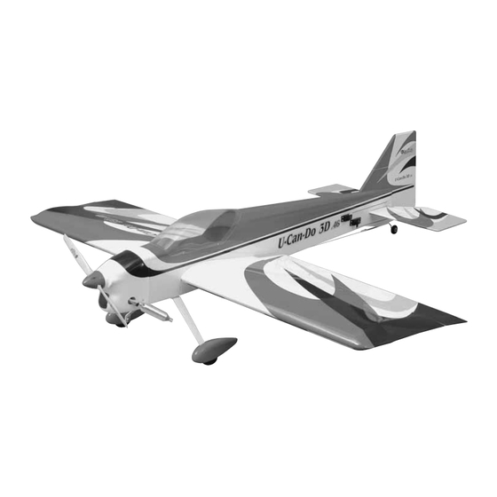
Wingspan: 56.75 in [1441mm]
Length: 58.5 in [1486mm]
Wing Area: 904 sq in [58.3 dm
Weight: 5 lbs - 5 lbs 10 oz [2268 - 2551g]
Wing Loading: 12.7 - 14.3 oz/sq ft [39 - 44 g/dm
Engine: .32 - .50 cu in [5 - 8cc] two-stroke, .52 - .70 cu in [9 - 11cc] four-stroke
Great Planes
®
Model Manufacturing Co. guarantees this kit to be free from defects in both material and workmanship at the date of
purchase. This warranty does not cover any component parts damaged by use or modification. In no case shall Great Planes' liability
exceed the original cost of the purchased kit. Further, Great Planes reserves the right to change or modify this warranty without notice.
In that Great Planes has no control over the final assembly or material used for final assembly, no liability shall be assumed nor
accepted for any damage resulting from the use by the user of the final user-assembled product. By the act of using the user-assembled
product, the user accepts all resulting liability.
If the buyer is not prepared to accept the liability associated with the use of this product, the buyer is advised to return this
kit immediately in new and unused condition to the place of purchase.
READ THROUGH THIS MANUAL BEFORE
STARTING CONSTRUCTION. IT CONTAINS
IMPORTANT WARNINGS AND INSTRUCTIONS
CONCERNING THE ASSEMBLY AND USE OF
THIS MODEL.
© Copyright 2003
INSTRUCTION MANUAL
]
2
2
]
WARRANTY
™
Champaign, Illinois
(217) 398-8970, Ext 5
airsupport@greatplanes.com
GPMZ0223 for GPMA1269 V1.0
Advertisement
Table of Contents

Related Manuals for GREAT PLANES U-Can-Do 3D.46


Summary of Contents for GREAT PLANES U-Can-Do 3D.46
-
Page 1: Instruction Manual
READ THROUGH THIS MANUAL BEFORE STARTING CONSTRUCTION. IT CONTAINS IMPORTANT WARNINGS AND INSTRUCTIONS Champaign, Illinois CONCERNING THE ASSEMBLY AND USE OF (217) 398-8970, Ext 5 THIS MODEL. airsupport@greatplanes.com © Copyright 2003 GPMZ0223 for GPMA1269 V1.0... -
Page 2: Table Of Contents
“tech IMPORTANT BUILDING NOTES........4 notice” box will appear in the upper left corner of the page. KIT CONTENTS..............5 ORDERING REPLACEMENT PARTS.......6 http://www.greatplanes.com/airplanes/index.html PREPARATIONS..............7 BUILD THE WING ..............7 Mount the Ailerons .............7 PROTECT YOUR MODEL, YOURSELF Install the Aileron Servos and Pushrods ......8... -
Page 3: Decisions You Must Make
wear safety goggles, a particle mask and rubber gloves when Rudder: grinding, drilling and sanding fiberglass parts.Vacuum the parts • One high torque servo (90+ in oz: FUTM0211) and work area thoroughly after working with fiberglass parts. • One 24" servo extension (HCAM2200) Elevator: •... -
Page 4: Covering Accessories
Hook & Loop Velcro ® (GPMQ4480) Small metal file 3' Medium fuel tubing (GPMQ4131) Rotary tool such as Dremel ® Easy Fueler ™ fuel filling valve for glow fuel (GPMQ4160) Rotary tool reinforced cut-off wheel (GPMR8200) Handy Mounts air valve, fuel filler mounts (GPMQ6000) Curved Tip Canopy Scissors for trimming plastic parts (HCAR0667) Dead Center... -
Page 5: Kit Contents
Kit Contents list on this page. Great Planes Product Support 3002 N. Apollo Drive, Suite 1 Champaign, IL 61822 Phone: (217) 398-8970 Fax: (217) 398-7721 E-mail: airsupport@greatplanes.com Kit Contents (Photographed) 1 Cowl 5 Canopy 9 Wheel pants 13 Cowl mounting blocks... -
Page 6: Ordering Replacement Parts
Support, but can be purchased from hobby shops or mail order/Internet order firms. Hardware items (screws, nuts, bolts) are also available from these outlets. If you need assistance locating a dealer to purchase parts, visit www.greatplanes.com and click on “Where to Buy.” If this kit is missing parts, contact Product Support at partssupport@greatplanes.com or (217) 398-8970. -
Page 7: Preparations
B) Both servo openings; PREPARATIONS C) Dowel hole; D) Top and Bottom wing-bolt holes. 1. If you have not yet done so already, remove the major parts of the kit from the box (wings, fuse, wheel pants, cowl, tail parts, etc.) and inspect them for damage. If any parts are damaged or missing, contact Product Support at the address or telephone number on page 5. -
Page 8: Install The Aileron Servos And Pushrods
5. Test fit the ailerons to the wing with the hinges. Use a 9. Stick a pin through the center of each hinge. Fit the fine-point ballpoint pen to mark the wing and ailerons at the ailerons to the wing with the hinges. The pin will keep the middle of each hinge. - Page 9 2. Using needle nose pliers, pull the string end out of 5. Make a mark on the bottom L.E. of the right aileron the right wing's servo hole. Tie the string to the end of the 7-3/4" [197mm] from the inboard end of the aileron. servo lead.
-
Page 10: Mount The Wing To The Fuselage
the pushrod where it crosses the servo arm. Bend the pushrod 90 degrees away from the wing on the mark you made. Enlarge to 5/64" Cut Off Unused Arms 8. Make a one-arm servo arm by cutting three arms off a four-arm servo arm. Enlarge the holes in the arm with a Hobbico Servo Horn Drill (or a #48 or 5/64"... -
Page 11: Build The Fuselage
3. With the wing mounted to the fuse. Place the model in a building stand (such as a Robart Super Stand II, ROBP1402). Stand five to ten feet behind the model and view the stab and wing. If the stab and wing align with each other, proceed to the next step. - Page 12 9. Attach the elevators to the stab with the same hinging technique used for the ailerons. 6. Use a fine-point felt-tip pen such as a Top Flite ® Panel Line Pen (TOPQ2510) to mark the outline of the fuse onto the top and bottom of the stab.
-
Page 13: Mount The Wheel Pants & Landing Gear
13. Attach the 1" [25mm] tail wheel with the 3/32" wheel collar and the 4-40 set screw. Mount the Wheel Pants & Landing Gear 14. Use a hobby knife or a 5/32" [4mm] brass tube sharpened on the end to cut a groove in the leading edge of the rudder to accommodate the nylon tail gear bearing. -
Page 14: Mount The Engine
centered over the hole in the pant. Glue the mount to the pant with 30-minute epoxy. The inside of the wheel pant mount has the 1/2" [13mm] hole. Hint: For the most secure bond, add microballoons (TOPR1090) or milled glass fibers (GPMR6165) to the epoxy. -
Page 15: Mount The Engine
Mount the Cowl 2. Trim the spreader bars from both halves of the engine mount. Mount the engine mount to the firewall with four 6-32 x 3/4" [19mm] SHCS, #6 flat washers and #6 lock washers, but do not fully tighten the bolts. 1. - Page 16 10. Use thin cardboard or plastic to make templates for the muffler, mixture screw, filler valve and glow plug cutouts 6. Align the ruler with the line on the fuselage. Mark the in the cowl. Tape the template(s) to the fuselage accurately center of the cowl mounting block on the cowl 4"...
-
Page 17: Install The Tank
not contact the rear of the tank. Otherwise, the line may Install the Tank become stuck above the fuel level and discontinue fuel flow. Remember (or use a felt-tip pen to mark) which tube is the fuel pick-up tube and which tube is the vent (that will be connected to the pressure fitting on the engine’s muffler). -
Page 18: Final Assembly
FINAL ASSEMBLY Install the Remaining Servos 4. Make a mark on the top L.E. of each elevator 5/8" [15.9mm] from the inboard edge of each elevator. Position the control horn centered over the mark. Mark the hole locations on the elevator. NOTE: The control horns mount on the top of the elevators with the pushrods going above the stab. - Page 19 7. Thread a clevis 25 turns onto one end of each of the three 12" [305mm] pushrods. Slip a silicone retainer over the clevises. 8. Make three one-arm servo arms. Enlarge the holes in the arm with a Hobbico Servo Horn Drill (or a #48 or 5/64" (2mm) drill bit) so the pushrod will fit.
-
Page 20: Mount The Canopy
Mount the Canopy 1. Use curved-tip scissors to cut out the canopy along the cut line. True the edges by sanding with medium-grit sandpaper. 16. Route the fuel lines as needed and mount the cowl, prop, muffler and spinner. 2. Place the canopy on the cockpit. Use a fine-point felt-tip pen to lightly trace the outline of the canopy onto the fuse. -
Page 21: Apply The Decals
Apply the Decals Set the Control Throws 1. Use scissors or a sharp hobby knife to cut the decals from Use a ruler or Great Planes Accu-Throw ™ Deflection Gauge the sheet. (GPMR2405) to accurately measure and set the control throw of each control surface as indicated in the chart that follows. -
Page 22: Balance The Model Laterally
PREFLIGHT Plane is balanced correctly when the bottom of the fuse is horizontal. 4-3/4" Identify Your Model [120mm] No matter if you fly at an AMA sanctioned R/C club site or if you fly somewhere on your own, you should always have your name, address, telephone number and AMA number on or inside your model. -
Page 23: Balance Propellers
Use a “chicken stick” or electric starter to start the engine. Ground Check Do not use your fingers to flip the propeller. Make certain the glow plug clip or connector is secure so that it will not pop If the engine is new, follow the engine manufacturer's off or otherwise get into the running propeller. -
Page 24: Radio Control
3. I will perform my initial turn after takeoff away from the pit 15. Make sure the fuel lines are connected and are or spectator areas and I will not thereafter fly over pit or not kinked. spectator areas, unless beyond my control. 16. -
Page 25: Takeoff
flight. After flying around for a while and while still at a safe CAUTION (THIS APPLIES TO ALL R/C AIRPLANES): If, altitude with plenty of fuel, practice slow flight and execute while flying, you notice any unusual sounds, such as a low- practice landing approaches by reducing the throttle to see pitched “buzz,”... -
Page 26: Performance Settings
but with the larger engines it requires extensive trimming of PERFORMANCE SETTINGS the spinner. If you have to extensively trim the spinner, we strongly suggest using an aluminum spinner instead. FOR THE U-CAN-DO 3D .46 ARF Servos After testing this plane with several different engines, props, CG locations and countless different control throw settings, Elevators: Futaba 9250 digital (FUTM0220) - Page 27 OTHER ITEMS AVAILABLE FROM GREAT PLANES Futaba ® S9151 Digital Rudder Servo (FUTM0211) Stock # FUTJ85** Length: 1.5 in 9CAF Width: 0.75 in R148DF Height: 1.4 in Servos (4) S3004 Weight: 1.75 oz Tx NiCd 700mAh Torque: 131.9 oz/in (4.8V) Rx NiCd 600mAh Speed: 0.19 sec @ 60°...
- Page 28 BUILDING NOTES Kit Purchased Date: _______________________ Date Construction Finished: _________________ Where Purchased:_________________________ Finished Weight: __________________________ Date Construction Started: __________________ Date of First Flight: ________________________ FLIGHT LOG...
Need help?
Do you have a question about the U-Can-Do 3D.46 and is the answer not in the manual?
Questions and answers