Table of Contents
Advertisement
Great Planes Model Manufacturing Co. guarantees this kit to be free from defects in both material and workmanship
at the date of purchase. This warranty does not cover any component parts damaged by use or modification. In no case
shall Great Planes' liability exceed the original cost of the purchased kit. Further, Great Planes reserves the right
to change or modify this warranty without notice.
In that Great Planes has no control over the final assembly or material used for final assembly, no liability shall be
assumed nor accepted for any damage resulting from the use by the user of the final user-assembled product. By the act
of using the user-assembled product, the user accepts all resulting liability.
If the buyers are not prepared to accept the liability associated with the use of this product, they are advised
to return this kit immediately in new and unused condition to the place of purchase.
READ THROUGH THIS INSTRUCTION MANUAL
FIRST. IT CONTAINS IMPORTANT INSTRUCTIONS
AND WARNINGS CONCERNING THE ASSEMBLY
AND USE OF THIS MODEL.
EXTGP03 V1.0 For GPMA0250
INSTRUCTION MANUAL
WARRANTY
P.O. Box 788
Urbana, IL 61801
productsupport@greatplanes.com
(217) 398-8970
Entire Contents © Copyright 2000
Advertisement
Table of Contents

Related Manuals for GREAT PLANES Giant Extra 330L


Summary of Contents for GREAT PLANES Giant Extra 330L
-
Page 1: Instruction Manual
In that Great Planes has no control over the final assembly or material used for final assembly, no liability shall be assumed nor accepted for any damage resulting from the use by the user of the final user-assembled product. By the act of using the user-assembled product, the user accepts all resulting liability. -
Page 2: Table Of Contents
PREFLIGHT....... . . 47 TABLE OF CONTENTS Charge the Batteries ......47 Balance the Propeller . -
Page 3: Introduction
Congratulations and thank you for purchasing the Great instances the plan and written instructions are correct. Planes 1/3 scale giant Extra 330L. We’d like to provide you a bit of history on our selection of this aircraft as the newest release in the Great Planes sport scale aerobatic line. -
Page 4: Decisions You Must Make
™ or other non-adhesive- and are listed for your ordering convenience. GPM is the backed hook-n-loop material Great Planes brand, TOP is the Top Flite ® brand, HCA is the Hobbico ®... -
Page 5: Optional Supplies & Tools
Drum, Cutting Burr, Cut-off Wheel ❏ Curved-Tip Canopy Scissors (HCAR0667) ❏ Servo Horn Drill (HCAR0698) On our workbench, we have three 11” Great Planes Easy-Touch ™ Bar Sanders, equipped with #80, #150 and #220-grit sandpaper. This setup is all that is required Important Building Notes for almost any sanding task. -
Page 6: Die-Cut Patterns
DIE-CUT PATTERNS... - Page 7 DIE-CUT PATTERNS...
-
Page 8: Common Abbreviations
(Continued from page 5) GET READY TO BUILD • Whenever just “epoxy” is specified you may use either 30-minute epoxy or 6-minute epoxy. When 30-minute epoxy is specified it is highly recommended that you 1. Unroll the plan sheets, then reroll the plan inside-out to use only 30-minute epoxy because you will need the make them lie flat. -
Page 9: Build The Tail Surfaces
Don’t forget to always of both sheets. cover the plans with Great Planes Plans Protector so the glue won’t stick to the plan. ❏ ❏ 1. Tape the left stab plan to the building board, and cover the stab drawing with Great Planes Plans Protector (so you won’t glue the stab to the plan!) - Page 10 ❏ ❏ 4. Carefully punch out the four die-cut 1/8" balsa stab ❏ ❏ 9. Carefully slide the stab LE web (SLE) onto the front webs (SLE, SMW, STE, and ELE), laser-cut 1/8" ply stab of the ribs in their notches. Glue all 8 ribs to all 3 webs and rib S1, die-cut 1/8"...
- Page 11 surface, then unpin the spars from the plan. Trim and sand the sheeting from the top side of the stab behind the main web and outboard of S7. Trim and sand the sheeting, spars and stab tube socket flush with the LE web, ribs S1 and S8. Hint: Now is a great time to make sure the top sheeting is firmly glued to all ribs, spars and webs.
-
Page 12: Finish The Elevators
❏ ❏ 2. Turn the stab right-side-up. Slide the elevator LE web (ELE) over the ribs in their notches until the top of the web is flush with the top of each rib. Glue in place with thin CA. NOTE for Non-Computer Radio and Entry Level Computer Radio Users: If you are using an entry level computerized radio, you will need to find out now whether or not your radio has the... - Page 13 ❏ ❏ 10. Measure 5/16" aft of the TE of S2 and S10, and draw ❏ ❏ 5. Place the S10 rib onto the elevator LE web. Place the a line between the 2 points. Cut the sheeting along this line die-cut 1/8"...
-
Page 14: Finish The Stab Panels
❏ ❏ 5. Using leftover 3/32" balsa, cap the outboard ends of both elevator halves and stab halves. Trim and sand the caps smooth. ❏ ❏ 6. Using giant scale hinges (not included — we used Robart Giant Scale Pin Hinges on the prototypes), hinge the elevator to the stab. -
Page 15: Build The Fin
Build the Fin that all references such as “laterally” and “model’s left” indicate the part’s final position on the finished model and ❏ 1. Cut the Fin plan from the plan sheet. Cover it with Great not necessarily its current orientation. Planes Plan Protector so the glue won’t stick to the plan. - Page 16 ❏ 16. Once the CA has fully cured, trim the rib tabs off with a razor saw. Sand the sheet and ribs flush with the LE web. ❏ 10. Position the first fin sheet flush against the fin post and the TE of the ribs, with the lower edge overhanging rib ❏...
-
Page 17: Build The Rudder
If you are going to double bevel your elevators, glue a 1/2" x 1-5/8" balsa spacer (not included) onto the leading edge of the fin post from V1 down to the bottom of the post. Build the Rudder ❏ 1. Select the two rudder sheets you made earlier. Trim the first sheet to size, using the 1"... -
Page 18: Build The Wing
❏ 10. From a 3/8" x 1-5/8" x 24" balsa stick, cut one 18-3/4" long rudder LE. From the 3/8" x 5/8" x 9" balsa stick leftover from making fin hinge blocks, cut three 1-1/2" long rudder hinge blocks. ❏ 14. Using medium CA, glue the rudder counterbalance to the rudder LE, aligning the tops of VR8 with V7 and centering the counterbalance’s TE on the rudder LE. -
Page 19: Build The Wing Panels
❏ ❏ 3. Tape the right wing plan to the building board, and cutting irregularities. Be careful not to alter the shapes or cover it with Great Planes Plan Protector (so you won’t glue angles of any of the pieces. - Page 20 ❏ ❏ 10. Position the remaining 13 ribs in place on the main web and spar. NOTE: If you happen to crack or break one of the ribs during installation, simply take it out of the wing, position the pieces together and glue them with thin CA. Allow the rib to dry and reinstall it.
- Page 21 ❏ ❏ 22. Position the main center sheet flush against the LE ❏ ❏ 26. Cut a 3/4" square from leftover 3/32" balsa. Use this sheet and the outboard edge of R3. Trim the center sheet piece to sheet over the bolt block and R4, allowing sufficient with the center line of the aileron spar.
- Page 22 45° throws. ❏ ❏ 39. With the wing upside-down, fit the aileron servo in Please read the Great Planes booklet: “A Look at place and trim the sheeting around the rubber grommets on Aerobatics”...
- Page 23 ❏ ❏ 45. Position your wing upside down on the work surface. Test position the aileron sheet even with the leading edge of the aileron spar and the inboard end of the aileron If you are installing the optional second aileron servo, glue end cap.
- Page 24 ❏ ❏ 52. Turn the wing right-side-up. Sand the trailing edge of Twin Servos Option the aft center sheet as you did the aileron sheet in step 46. If you chose to install twin aileron servos, repeat steps 44 and 45, securing the second set of control horn mounts against the outboard edge of R11.
-
Page 25: Build The Fuselage
❏ ❏ 59. Shape the leading edge to transition between the ❏ ❏ 64. Glue a 1/2" x 1-1/4" x 42" balsa stick, the aileron templates provided. Note: There is one template for the root leading edge, to the leading edge of the aileron spars. which is fairly wide and blunt. -
Page 26: Build The Fuselage Center Box Sides
❏ ❏ 2. Unroll your fuse plan onto your work surface. Be sure to cover it with Great Planes Plan Protector. Select one 1/8" die-cut ply FCB1 and FCB3 and one 1/8" laser-cut ply FCB2 and FCB4. -
Page 27: Assemble The Fuselage Center Box
❏ 12. Unpin the right fuse side from the plan. Flip it over so toward the front of the aircraft AND with the “top” label, if the right inside is now against the work surface. Cover the applicable, toward the top of the aircraft. right fuse side with Great Planes Plan Protector. - Page 28 ❏ 1. Select the die-cut 1/8" ply tail gear mount (TGM) and tail gear mount doubler (TGMD). Glue the doubler to the tail gear mount, aligning the leading and trailing edges. This assembly is now known as the tail gear mount assembly. ❏...
- Page 29 vertical trusses. Glue F7 and then F6 in position. DESIGNER’S NOTE: Steps 10 through 12 are where the fuselage is locked into its final configuration. Check for straightness and be sure the fuse is positioned properly over the plan. It is CRITICAL that it does not have a twist or banana shape.
-
Page 30: Install The Firewall
❏ 12. Turn the fuselage right-side-up. Using 1/4" x 1/4"x 36" ❏ 3. Temporarily mount your engine to the firewall, centered balsa sticks, fit and glue the 3 upper diagonal cross trusses. on the marks you just made. This is the technique we used Note: The upper cross trusses run opposite to the lower to mount the MacMinarelli engines: mark the four holes for cross trusses as shown on the plan. -
Page 31: Mounting The Wing And Tail
❏ ❏ 3. Using an 11/64" drill bit, drill 2 holes through each ❏ 8. Drill a 5/32" hole which is centered on the fuselage and doubler, forward box side and landing gear support. The is 3-1/4" forward of the fuse’s trailing edge as shown in holes are positioned 1/2"... - Page 32 ❏ 3. Slide the 36" aluminum tube through the fuse. Center INSTALLING YOUR WING the tube on the fuse, and mark the tube with a permanent marker where it exits both of the center box sides. When you fit the Extra’s wing to the tube, you will find it is a snug fit that requires some force.
-
Page 33: Install The Fuselage Outer Shell
OK, had an evening to show off your progress? Terrific, let's get back to work. ❏ 19. Remove the wings, stab, anti-rotation dowels, and main and tail gear and set them aside. Leave the tank/servo tray in place but DO NOT glue. Install the Fuselage Outer Shell ❏... -
Page 34: Build The Outer Shell Stringers
❏ ❏ 3. Fit and glue one of each of the die-cut 1/8" ply SF5 ❏ ❏ 2. Select one of the four outer shell stringers to be used and SF6 in position. Note that SF5 aligns with F5, and SF6 as the right upper outer shell stringer. -
Page 35: Sheeting The Fuselage
of F9 and with the very trailing edge corner flush against the Sheeting the Fuselage top of the bottom inner box longeron. Carefully position and glue the stringer flush with the outer edge of F8, NOT touching the trusses. Glue the stringer into the notches in DESIGNER’S NOTE: The sheeting on this fuselage is the remaining formers and cut the excess off flush with SF1. - Page 36 ❏ 16. Cut two 3/32" x 1/4" x 36" balsa sticks into six 12" fuse side shapers. Cut an angle on each one to match the angle of the side sheeting when positioned lengthwise so it is 3/32" wide and 1/4" tall. Position and glue each shaper along the outer shell stringers (3 on each side) and flush against the fuse outer shell sheeting.
-
Page 37: Build The Front Deck
❏ 4. From leftover 1/4" x 1/4" balsa stick, position and glue the center top deck stringer and trim it flush with the leading edge of FD1 and the trailing edge of FD3. ❏ 5. From six 1/8" x 1/4" x 36" balsa sticks, cut six 10" long front deck side stringers. -
Page 38: Mount The Cowl
❏ 10. Test wrap the sheet over the front deck several times until you can comfortably get it tight along the formers and running along the outer shell sheet. When you are confident that you have a good, tight fit and the sheeting isn’t going to split, trim the right side of the sheet until it mates up to the outer shell sheeting and the gluing stringer as the left side does. -
Page 39: Build The Turtle Deck
center stringer into the notches in TD4 then, TD3 and then, Build the Turtle Deck TD2, leaving the excess overhanging past TD2. NOTE: Be careful to keep the formers vertical. ❏ 1. Position and glue the die-cut 1/8" ply formers TD4, TD3 and TD2 vertically against the trailing edge of formers F9, F8 and F7 respectively, centering the parts side-to-side. - Page 40 sheeting across the rear of the fuse. Allow the sheeting to dry completely overnight. NOTE: This is probably the most time consuming step of the entire kit. Take your time and be patient, being careful not to split the sheeting. If you are patient and allow the water and gravity to work together, the sheeting will bend smoothly and cleanly and you’ll get a great looking turtle deck.
-
Page 41: Install The Cockpit & Canopy
and the TE of the fuse. Do not disturb for at least ½ hour to allow the epoxy to fully and properly cure. ❏ 22. Using a piece of leftover 3/8" x 5/8" balsa, cut a 1-1/2" long hinge block. Using the plan as a reference, locate the lowest hinge block in the rudder, and glue the hinge block you just made into the fuse against the F11 at that location. - Page 42 the perimeter of the front and rear deck sheeting just as you did with the floor sheeting. Sand the formers as needed. When you are comfortable with the fit and positioning, glue IP and CPR to the floor sheeting, being careful not to glue any of the cockpit components to the fuselage.
-
Page 43: Mount The Wheels & Wheel Pants
From leftover 1/4" x 1/4" basswood, cut two 2" long cockpit FINISH THE MODEL bolt supports. Reach in through the fuselage and glue the bolt supports to the aft end of the bottom of the cockpit floor, flush against, but not glued to, the insides of the upper outer Balance the Model Laterally shell stringers. -
Page 44: Paint The Model
On the prototype we (Note that the recommended Great Planes 24 oz. tank and used Dubro ®... -
Page 45: Set The Control Throws
Moving the balance aft makes the model most proportional movement). more agile with a lighter, snappier “feel” and often improves Please read the Great Planes booklet: “A Look at knife-edge capabilities. In any case, please start at the Aerobatics” for more information. -
Page 46: Assembly & Maintenance
❏ 1. The phenolic tube sockets will gradually wear and feel loose when you’re assembling your model to fly. When they Using a Great Planes CG Machine do, apply a small amount of thin CA to a paper towel and... -
Page 47: Preflight
power indefinitely. The engine must be “broken-in” on the PREFLIGHT ground by running it for at least two tanks of fuel. Follow the engine manufacturer’s recommendations for break-in. At this time check all connections including servo arm Make sure all screws remain tight, that the hinges are secure screws, clevises and servo wires. -
Page 48: Ama Safety Code (Excerpt)
The Great Planes Extra 330L is a great flying semi-scale sport model that flies smoothly and predictably, yet is highly Make all engine adjustments from behind the rotating propeller. -
Page 49: Takeoff
Takeoff Landing Takeoff on “low” rates if you have dual rates on your When it’s time to land, fly a normal landing pattern and transmitter–even if you are taking off in a crosswind. For all approach. Keep a few clicks of power on until you are over models it is good practice to gain as much speed as the the runway threshold. - Page 50 ™ ™ AVIOmac Giant-Scale Gasoline Engines Easy starts...ultra-smooth performance...unequalled value! • Superior power PLUS exceptional economy for 1/3 and 1/4 scale R/C aircraft. • Includes clearly written instructions, exploded parts diagrams AND 3-year warranty protection. MMLG0085 MMLG0070 70 Twin 85 Twin Bore: 1.46 in Bore: 1.65 in Stroke: 1.22 in...
- Page 51 Futaba 9-Channel “Z-Series” Futaba 8UAPS 8-Channel Radios PCM Radios Advanced features like audible trims The choice of the world’s best pilots! let you hear the superiority of Futaba design! The ultimate in performance and versatility. FUTJ93** - FUTJ9550 FUTJ81** SYSTEM FUTJ93** 9ZAW FUTJ9550 9ZAWS SYSTEM 8UAPS...
-
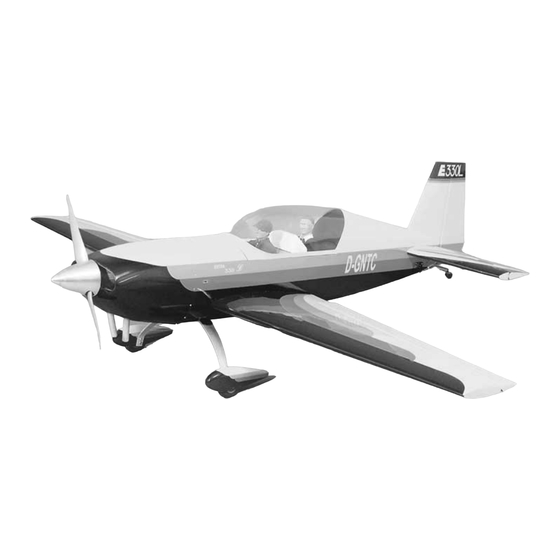
Page 52: 2-View
2-View Use the 2-view or photocopy it and use the copy to design your trim scheme.
Need help?
Do you have a question about the Giant Extra 330L and is the answer not in the manual?
Questions and answers