Table of Contents
Advertisement
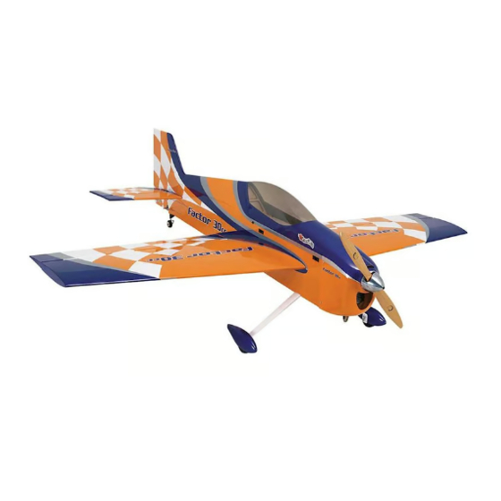
SPECIFICATIONS
Wingspan:
70 in [1174 mm]
Length:
75 in [1905 mm]
Wing Area:
1174in
2
[ 75.7dm
WARRANTY
Great Planes
®
Model Manufacturing Co. guarantees this
kit to be free from defects in both material and workmanship at
the date of purchase. This warranty does not cover any
component parts damaged by use or modification. In no case
shall Great Planes' liability exceed the original cost of
the purchased kit. Further, Great Planes reserves the right to
change or modify this warranty without notice.
In that Great Planes has no control over the final assembly or
material used for final assembly, no liability shall be assumed nor
accepted for any damage resulting from the use by the user of
the final user-assembled product. By the act of using the
user-assembled product, the user accepts all resulting liability.
If the buyer is not prepared to accept the liability
associated with the use of this product, the buyer is
READ THROUGH THIS MANUAL BEFORE STARTING CONSTRUCTION. IT CONTAINS IMPORTANT
INSTRUCTIONS AND WARNINGS CONCERNING THE ASSEMBLY AND USE OF THIS MODEL.
© 2016 Great Planes Model Mfg. A subsidiary of Hobbico,
Weight:
12 – 14 lbs [ 5440 – 6350 g]
Wing
24– 27 oz/ft
Loading:
2
]
Radio:
4− 7 Channel
®
Inc.
INSTRUCTION MANUAL
Engine:
2
[ 73– 82 g /dm
2
]
Motor:
advised to return this kit immediately in new and
unused condition to the place of purchase.
To make a warranty claim send the defective part or item to
Hobby Services at the address below:
Hobby Services
3002 N. Apollo Dr. Suite 1
Champaign IL 61822 USA
Include a letter stating your name, return shipping address, as
much contact information as possible (daytime telephone
number, fax number, e-mail address), a detailed description of
the problem and a photocopy of the purchase receipt. Upon
receipt of the package the problem will be evaluated as quickly
as possible.
Champaign, Illinois
(217) 398-8970, Ext 5
airsupport@greatplanes.com
1.8−2.0 cu in (30– 35 cc)
gasoline engine
RimFire 1.60 (63-62-250)
outrunner brushless
GPMA1555
Advertisement
Table of Contents

Related Manuals for GREAT PLANES Factor 30cc


Summary of Contents for GREAT PLANES Factor 30cc
-
Page 1: Instruction Manual
3002 N. Apollo Dr. Suite 1 Champaign IL 61822 USA In that Great Planes has no control over the final assembly or material used for final assembly, no liability shall be assumed nor Include a letter stating your name, return shipping address, as... -
Page 2: Table Of Contents
Continuing with the success of the Factor 3D EP, Great As a new owner of an unmanned aircraft system (UAS), you Planes brings you the Factor 30cc ARF. This is a great first are responsible for the operation of this vehicle and the safety gas powered 3D model. -
Page 3: Decisions You Must Make
Always wear safety goggles, a particle mask and rubber gloves when grinding, drilling and sanding fiberglass The Factor 30cc ARF can be fl own with a minimum of a parts. Vacuum the parts and the work area thoroughly after 4-channel radio. -
Page 4: Additional Items Required
❍ Top Flite MonoKote Heat Gun (TOPR2000) This is the list of Adhesives and Building Supplies that are required to fi nish the Factor 30cc ARF. ❍ Coverite 21st Century Sealing Iron (COVR2700) ❍ 1/2 oz. [15g] Thin Pro CA (GPMR6001) ❍... -
Page 5: Important Building Notes
IMPORTANT BUILDING NOTES REPLACEMENT PARTS LIST ● Anytime thin CA glue is recommended Replacement parts for the Great Planes Factor 30cc ARF are you will see this symbol. We available using the order numbers in the Replacement Parts recommend that when threading List that follows. -
Page 6: Preparations
PREPARATIONS ❏ 1. Firmly pull on each aileron to confi rm they are securely glued. ❏ 2. Tighten the covering with a covering iron. ASSEMBLE THE WING Aileron Servo Installation BEGIN WITH THE LEFT WING PANEL. ❏ ❏ 3. Route servo lead through wing. ❏... - Page 7 ❏ ❏ 6. Install servo horn. ❏ ❏ 7. Aileron pushrod components. ❏ ❏ 11. Mount control horn. ❏ ❏ 8. Install the 4-40 threaded clevis. ❏ 9. Attach clevis to control horn. ❏ ❏ ❏ ❏ 12. Install the solder clevis. 10.
-
Page 8: Assemble The Fuselage
HOW TO SOLDER Apply a few drops of soldering fl ux to the end of the pushrod. “Tin” the end of the pushrod by applying heat. ❏ Apply silver solder to the heated area. The pushrod should 15. Install the nylon wing dowels. melt the solder, not the fl ame of the torch. - Page 9 ❏ ❏ 3. Temporarily install the horizontal stabilizer. 8. Position the tail gear by temporarily installing the rudder. ❏ 4. Check the alignment of the horizontal stabilizer. The distance from the center of the nose of the fuselage to the tips of the horizontal stabilizer should be equal.
- Page 10 ❏ 12. Install the set screws in the wheel collars. ❏ 13. Install the tail wheel. ❏ 11. Use 30-minute epoxy to glue in the hinges. ❏ 14. Install the two elevators following the same procedure used for installing the rudder.
-
Page 11: Install The Main Landing Gear
Install the Main Landing Gear ❏ 1. Install the 3/16” [5mm] axles. ❏ 2. Cut the axle to length. ❏ 5. Install the wheel pants. ❏ 3. File a fl at spot at the end of the axle. ❏ 6. Install the main landing gear on the fuselage. ❏... -
Page 12: Install The Rudder And Elevator Servos
Install the Rudder and Elevator Servos ❏ 1. Make a battery strap from the supplied hook and loop material. ❏ 2. Wrap the receiver in foam and secure it to the receiver tray with a hook and loop strap. ❏ 6. - Page 13 ❏ 9. Position the rudder control horn. ❏ 11. Attach a second set of clevises, 4-40 couplers, 4-40 nuts and silicone clevis retainers to the rudder control horns. ❏ 12. Attach the clevises to the control horns and pull the ❏...
- Page 14 ❏ 13. Install the 4-40 x 48” (1220mm) elevator pushrods. ❏ 15. Install the elevator control horns and attach the 4-40 clevises, nuts and retainers. ❏ 14. Install the elevator servos. The two servo leads can be joined with a Y-harness and plugged into the receiver or each servo can be plugged into a separate channel in the receiver.
-
Page 15: Power System Installation
❏ ❏ 17 Solder the clevises to the elevator pushrods. 2. Glue the sides on using epoxy. POWER SYSTEM INSTALLATION Electric Motor Installation Proceed to Gas Engine Installation (page 7) if a gas engine will be installed. ❏ 3. Glue eight pieces of triangle stock between the front plate and the sides and the back plate and the sides using epoxy. -
Page 16: Assemble The Removable Battery Tray
❏ 5. Open the cooling hole. Use a small drill bit to drill out ❏ 9. Install the forward battery hatch in the fuselage. each tab. ❏ 7. Attach the motor box to the fi rewall. ❏ 10. Mount the ESC. Connect the wires from the ESC to the motor wires. - Page 17 ❏ 4. Securely glue the 4 x .7mm blind nut in the plate. ❏ 5. Make two battery straps from the supplied hook and loop material. ❏ 3. Glue the plate to the back of the battery tray. Before the epoxy cures, insert the battery tray in the fuselage and check that the holes line up.
- Page 18 ❏ 9. Secure the fl ight batteries on the battery tray. ❏ 10. Secure the battery tray in the fuselage. ❏ 7. Test fi t the battery tray in the fuselage. ❏ 11. Install the receiver battery tray. ❏ 8. Apply a couple of pieces of adhesive backed Velcro (not included) to the battery tray and the opposite side to the battery.
-
Page 19: Gas Engine Installation
❏ 13. Switch on the transmitter and temporarily plug in the receiver battery. Connect the motor batteries to the ESC and check the rotation direction of the motor. WARNING! Make sure the propeller is NOT installed. ❏ 14. Disconnect the motor batteries, receiver battery and switch off the transmitter. - Page 20 ❏ 2. Solder fuel line barbs onto one end of the brass tubes. ❏ 6. Install the two fuel pickup lines. ❏ 3. Insert the brass tubes in the fuel tank stopper and stopper plates. Loosely install the fuel tank stopper screw. ❏...
- Page 21 ❏ 10. Make three straps from the hook and loop material. ❏ 11. Wrap the ignition module in foam and secure it to the bottom of the fuselage with a hook and loop strap. ❏ 14. Install the forward battery hatch in the fuselage. ❏...
-
Page 22: Install The Throttle And Optional Choke Servos
❏ 3. Make two straps from the remaining hook and loop material. Install the receiver battery and receiver switch. ❏ 17. Attach the line from the pickup tube to the carburetor. Install the Throttle and Optional Choke Servos ❏ 4. Install the throttle and optional choke servo and plug them into the receiver. - Page 23 ❏ 7. Assemble the throttle clevis. ❏ 12. Install the outer pushrod tube. ❏ 8. Install the clevis on the throttle servo. ❏ 9. Attach the 2-56 × 1" [25mm] threaded rod to the throttle pushrod. It is easier to remove the pushrod from the throttle ❏...
- Page 24 closes smoothly. We recommend that a throttle cutoff also Choke Option #2 be set up on the transmitter to close the throttle completely, stopping the engine. ❏ 1. Install the pivot ball socket. ❏ 15. Glue the outer pushrod support to the outer pushrod and the fuselage.
-
Page 25: Install The Cowl
Choke Option #3 ❏ 1. Insert the choke pushrod. ❏ 2. Install the pivot ball socket. Install the Cowl For the electric installation, skip to step 2. ❏ 2. Position the cowl. ❏ 1. Trim the cowl as shown to clear the muffl er exhaust ❏... -
Page 26: Apply The Decals
Apply the Decals 1. The decals are die-cut from the factory. 2. Be certain the model is clean and free from oily fi ngerprints and dust. Prepare a dishpan or small bucket with a mixture of liquid dish soap and warm water – about 1/2 teaspoon of soap per gallon of water. -
Page 27: Set The Control Throws
Set the Control Throws ❏ 1. Hold a ruler against the widest part of the control surface and measure the high rate throw fi rst. ❏ 4. Once the throws are set, apply a drop of threadlocker to the threads and tighten the 4-40 nuts against the clevises. Slide the silicone retainers over the clevises. -
Page 28: Balance The Model Laterally
2. With the plane ready to fl y, with an empty fuel tank or the batteries into the ESC. motor batteries installed, use a Great Planes C.G. Machine or apply narrow (1/16” [2mm]) strips of tape at the front and rear ❏... -
Page 29: Preflight
gas engines, if the engine should backfi re, the large prop PREFLIGHT can cause severe injury to your hand and fi ngers. ● Do not run the engine in an area of loose gravel or sand; Identify Your Model the propeller may throw such material in your face or eyes. ●... -
Page 30: Ama Safety Code
● The Factor 30cc ARF is a great-fl ying sport/3D model that If the battery starts to swell, quickly move the battery to fl ies smoothly and predictably. However, it does not possess a safe location, preferably outside. -
Page 31: Flight
Gain as much speed as your runway and fl ying site The Factor 30cc is easy to land. We recommend landing on will practically allow before gently applying up elevator, lifting high rate throws. - Page 32 Tape to the underside of the canopy: Tape inside your plane: LOW RATE HIGH RATE 3D RATE This model belongs to: 3/4" 1-1/8" 4-1/4" Up and Up and Up and [19mm] [29mm] [108mm] Down Down Down 6° 9° 37° Name 1-5/8"...
Need help?
Do you have a question about the Factor 30cc and is the answer not in the manual?
Questions and answers