Table of Contents
Advertisement
Quick Links
Wingspan: 78.5 in [1995mm]
Wing Area: 1180 sq in [76 dm
Weight: 14.25 – 16.5 lb [6500g – 7500g]
Wing Loading: 27.8 oz/sq ft [85g/dm
Length: 70 in [1780mm]
Radio: 4-channel minimum (7 to 8 servos)
Engine: 1.60 to 2.10 cu in [25 to 35cc] 2-stroke,
2.00 to 3.00 cu in [33 to 50cc] 4-stroke,
2.5 to 3.8 cu in [41 to 65cc] Gas
Model Manufacturing Co. guarantees this kit to be free from defects in both material and workmanship at the date of purchase.
Great Planes
®
This warranty does not cover any component parts damaged by use or modification. In no case shall Great Planes' liability exceed the
original cost of the purchased kit. Further, Great Planes reserves the right to change or modify this warranty without notice.
In that Great Planes has no control over the final assembly or material used for final assembly, no liability shall be assumed nor accepted for
any damage resulting from the use by the user of the final user-assembled product. By the act of using the user-assembled product, the user
accepts all resulting liability.
If the buyer is not prepared to accept the liability associated with the use of this product, the buyer is advised to return this kit
immediately in new and unused condition to the place of purchase.
READ THROUGH THIS MANUAL BEFORE STARTING
CONSTRUCTION.
INSTRUCTIONS AND WARNINGS CONCERNING
THE ASSEMBLY AND USE OF THIS MODEL.
GPMZ0216 for GPMA1305 V1.0
INSTRUCTION MANUAL
2
]
2
]
IT
CONTAINS
WARRANTY
IMPORTANT
1610 Interstate Drive Champaign, IL 61822
(217) 398-8970, Ext. 2
airsupport@greatplanes.com
Entire Contents © Copyright 2002
Advertisement
Table of Contents

Related Manuals for GREAT PLANES Extra 300S ARF


Summary of Contents for GREAT PLANES Extra 300S ARF
-
Page 1: Instruction Manual
Further, Great Planes reserves the right to change or modify this warranty without notice. In that Great Planes has no control over the final assembly or material used for final assembly, no liability shall be assumed nor accepted for any damage resulting from the use by the user of the final user-assembled product. -
Page 2: Table Of Contents
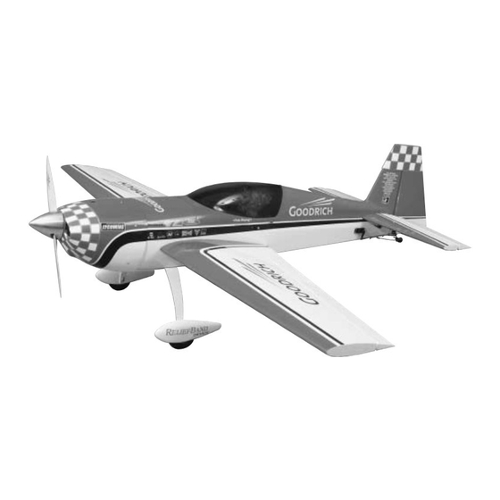
ADDITIONAL ITEMS REQUIRED ........4 is a versatile airplane designed for giant-scale aerobatics. The Hardware & Accessories ..........4 Extra 300S ARF is capable of wild, 3D aerobatics while still Adhesives & Building Supplies ........5 keeping the slow speed and landing performance of a low Optional Supplies &... -
Page 3: Safety Precautions
If you have not flown this type of model before, we 1. Your Extra 300S ARF should not be considered a toy, but recommend that you get the assistance of an experienced rather a sophisticated, working model that functions very pilot in your R/C club for your first flights. -
Page 4: Radio Equipment
Radio Equipment ADDITIONAL ITEMS REQUIRED The Extra 300S ARF can use a simple 4 to 6-channel radio with several “Y” reversing and non-reversing harnesses or it Hardware & Accessories can use a 6 to 10-channel computer radio. Even though the... -
Page 5: Adhesives & Building Supplies
Single-sided foam tape (wing seating tape, GPMQ4422) In addition to common household tools and hobby tools, this is the “short list” of the most important items required to build the Extra 300S ARF. Great Planes Pro ™ CA and IMPORTANT BUILDING NOTES Epoxy glue are recommended. -
Page 6: Metric/Inch Ruler
ORDERING REPLACEMENT PARTS To order replacement parts for the Great Planes Extra 300S ARF, use the order numbers in the Replacement Parts List that follows. Replacement parts are available only as listed. Not all parts are available separately (an aileron cannot be purchased separately, but is only available with the wing kit). -
Page 7: Kit Contents
If any parts are missing or are not of acceptable quality, or if you need assistance with assembly, contact Great Planes Product Support. When reporting defective or missing parts, use the part names exactly as they are written in the Kit Contents list on this page. -
Page 8: Building Instructions
BUILDING INSTRUCTIONS Preparations 1. If you have not done so already, remove the major parts of the kit from the box (wings, fuselage, cowl, tail parts, etc.) and inspect them for damage. If any parts are damaged or missing, contact Product Support at the address or telephone number listed in the front cover. - Page 9 8. Feel through the MonoKote covering on the bottom surface of the wing and find the opening for the aileron servo. Cut the covering 1/8" [3.2mm] inside the opening. Use a sealing iron or trim seal tool to seal the covering to the edges of the opening.
- Page 10 HOW TO SOLDER A. Use denatured alcohol or other solvent to remove residual oil from the pushrod. B. Use coarse sandpaper to thoroughly roughen the end of the pushrod where it is to be soldered. C. Apply a few drops of soldering flux to the end of the pushrod, then use a soldering iron or a torch to heat the end of the pushrod.
-
Page 11: Mount The Wing To The Fuselage
Feel through the MonoKote for the stabilizer slot in the aft part of the fuselage. Cut away the MonoKote from the slots on both sides of the fuselage and then seal the edges with a sealing iron or a trim seal tool. 16. -
Page 12: Engine Mounting Preparations
Once the glue has cured, install the servo tray in place as shown using 6-minute epoxy. The notched side fits against the former. Engine Mounting Preparations 4. Mix some 30-minute epoxy. Wick some epoxy inside the holes drilled in the previous step. Insert a 1/8" [3.2mm] dowel inside a hole and slide it in and out several times to make sure that it is coated in epoxy. -
Page 13: Install The Engine
Center the molded-in “tick” marks on both the top and bottom of the engine mount with the marks on the firewall and tighten the mounting bolts. It would be a good idea to use some Great Planes Pro Threadlocker ™... - Page 14 Connect the pushrod to the carburetor arm with the Screw-Lock pushrod connector. Use Great Planes Pro Threadlocker on the 4-40 x 1/4" [6.4mm] SHCS for the Screw-Lock pushrod connector 7. Install the muffler for your engine. A Pitts-style Bisson and tighten it.
-
Page 15: Install A Gas Engine
Aluminum Fuel Line Plug (GPMQ4166) to plug the fill fuel line. If you wish, you could install a Great Planes Easy Fueler Valve for glow engines (GPMQ4160) instead of the third (fill) line in the tank. - Page 16 4. Install the engine in place with the hardware recommended by the manufacturer. For the Fuji BT-50SA you should use 6. Cut a 36" [914mm] plastic outer pushrod (not included) 1/4-20 x 1" [25mm] bolts with 1/4-20 blind nuts and 1/4" so that you have one 19"...
- Page 17 #2 x 3/8" [9.5mm] screws. 12. Install the gas fuel tank of your choice in the fuselage. You will either need a three-line fuel system or a two line fuel system with a Great Planes Easy Fueler Valve. If you use...
-
Page 18: Install The Cowl
the three line system, you will need to route the carburetor line to the carburetor fuel nipple and the vent and fill lines to the front of the firewall. Glue a block of balsa to the firewall and make a hole through it of the size of the vent tube. Slide the vent tube through the balsa block. -
Page 19: Install The Tail Surfaces
Remove the screws and apply some thin CA into the holes to strengthen the threads. Note: The Extra 300S ARF has a plug-in stabilizer. The stabilizer is comprised of three built up parts, the stab center-section, and the left and right stab panels. To separate the outer panels you need to remove the four 4-40 x 3/4"... - Page 20 align the arrow with one corner of the stab as shown in the photo. Swing the string over to the same position on the other corner of the stab. Rotate the stab and slide the tape along the string until the arrow aligns with both sides. Be certain the stab remains centered from side-to-side during this process.
- Page 21 HOW TO CUT COVERING FROM BALSA 9. Remove the stabilizer outer panels from the fuselage. Feel through the MonoKote on the bottom surface of the stabilizer and find the openings for the elevator servos. Cut the covering 1/8" [3.2 mm] inside the opening. Use a sealing iron or trim seal tool to seal the covering to the edges of the Use a soldering iron to cut the covering from the wing.
- Page 22 not drill through the other side of the elevator. Wick some thin CA into the holes and re-install the control horn using four #4 x 5/8" [16mm] screws. Tighten the hex nut against the threaded clevis. Repeat this procedure for the other elevator. 14.
-
Page 23: Install The Landing Gear
17. Use the same procedure described on steps 11, 12, and 13 of the elevator pushrod setup to make the rudder 2. Insert the tail wheel wire into the hole. Find two “U” pushrods except that the rudder pushrods need to be 6-1/2" shaped nylon straps and place them over the wire as [165mm] long when cut and 8-1/2"... - Page 24 4-40 x 1/4" [6.4mm] SHCS to tighten the wheel collars. Use Great Planes Pro Threadlocker on the SHCS. Slip a silicone retainer onto both tail wheel pushrod clevises.
- Page 25 10. Look carefully at the wheel pants. Locate a dimple that indicates the wheel axle location on the side of the 14. Mount the wheel and wheel pant to the axle with two wheel pant. Use a high speed rotary tool to drill a 1/2" #8 washers, and a wheel collar.
-
Page 26: Finish The Radio Installation
17. Remove the wheel pants from the axle and wick 2. Drill a small hole at the bottom of the fuselage and some thin CA into the holes you just drilled. Permanently route the receiver antenna to the rear of the airplane. Use a install the wheel pants and wheels in place using two #4 x rubber band to keep it stretched. -
Page 27: Finish The Cockpit
Finish the Cockpit Apply the Decals 1. Use scissors or a sharp hobby knife to cut the decals from the sheet. 2. Be certain the model is clean and free from oily fingerprints and dust. Prepare a dishpan or small bucket with a mixture of liquid dish soap and warm water–about one teaspoon of soap per gallon of water. -
Page 28: Set The Control Throws
If, after you have become accustomed to the way and/or receiver must be shifted aft or weight must be added the Extra 300S ARF flies, you would like to change the to the tail to balance. If possible, relocate the battery pack throws to suit your taste, that is fine. -
Page 29: Balance The Model Laterally
We use a Top Flite Precision Magnetic Prop Balancer ™ (TOPQ5700) in the workshop and keep a Great Planes Fingertip Prop Balancer (GPMQ5000) in our flight box. PREFLIGHT Ground Check Identify Your Model If the engine is new, follow the engine manufacturer’s... -
Page 30: Engine Safety Precautions
The engine gets hot! Do not touch it during or right after Since the Extra 300S ARF qualifies as a “giant-scale” operation. Make sure fuel lines are in good condition so fuel model and is therefore eligible to fly in IMAA events, will not leak onto a hot engine, causing a fire. - Page 31 multi-winged model aircraft and have a ramp weight (fueled Servos need to be of a rating capable to handle the loads and ready to fly) of 55 lbs. or less. that the control surfaces impose upon the servos. Standard servos are not recommended for control surfaces. Servos Section 1.0: SAFETY STANDARD should be rated heavy-duty.
-
Page 32: Check List
Extend your receiver antenna and make sure it has a strain relief inside the fuselage to keep tension off The Extra 300S ARF is a great-flying model that flies smoothly and predictably. The Extra 300S ARF does not, the solder joint inside the receiver. -
Page 33: Takeoff
The Extra 300S ARF will perform 3-D aerobatics easily if Take it easy with the Extra 300S ARF for the first few flights, you use the larger engines recommended within the engine gradually getting acquainted with it as you gain confidence. -
Page 34: 3D Control Throws
Larger than stock servo arms are highly recommended for getting the 3D throws for the Extra 300S ARF. Do not Exponential, the best of both rates: Exponential is a move the pushrods in on the control horns to get the feature which modelers tend to either love or hate. -
Page 35: Appendix
Great Planes at (217) 398-8970 Do all maneuvers at full throttle. The only deviation from this is if A model is not a static object. Unlike a car, which you can only... - Page 36 Great Planes 1/4-Scale Giles G-202 ARF Reprinted in part by Great Planes Model Manufacturing Company, Designed to convince “kitters” that ARFs can be courtesy of Scale R/C Modeler magazine, Pat Potega, Editor, outstanding! Parts interlock for strength, and are all-wood August 1983 issue.
- Page 37 One leading cause of crashes is flying an airplane with its control throws set differently from those recommended in power. Comes with muffler, mount and Champion RCJ6Y the instructions. The Great Planes AccuThrow lets you spark plug. FJIG0050...
-
Page 38: Flight Trimming
TRIM FEATURE MANEUVERS OBSERVATIONS CORRECTIONS CONTROL Fly general circles and Try for hands off straight Readjust linkages so that CENTERING random maneuvers. and level flight. Tx trims are centered. CONTROL Random maneuvers A. Too sensitive, jerky If A, change linkages to THROWS controls. -
Page 39: Tail Wheel Pushrod Pattern
BUILDING NOTES Kit Purchased Date: _______________________ Date Construction Finished: _________________ Where Purchased:_________________________ Finished Weight: __________________________ Date Construction Started: __________________ Date of First Flight: ________________________ FLIGHT LOG TAIL WHEEL PUSHROD PATTERN ENGINE MOUNT TEMPLATE EM218 BOLT PATTERN USE 10-32 BOLTS AND BLIND NUTS IN A TYPICAL INSTALLATION...
Need help?
Do you have a question about the Extra 300S ARF and is the answer not in the manual?
Questions and answers