Table of Contents
Advertisement
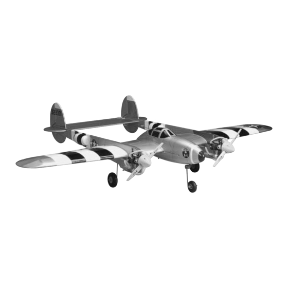
Wingspan: 50 in [1270mm]
Wing Area: 416 sq in [27dm
Weight: 4 – 5 lbs [1810 – 2270g]
Wing Loading: 22 – 27 oz/sq ft [68 – 85g/dm
Length: 36 – 3/4 in [933mm]
Radio: 4-channel transmitter with 6 standard servos
Engine: .15 – .25 cu. in. [2.5 – 4.0cc] two-stroke
Great Planes
®
Model Manufacturing Co.
purchase. This warranty does not cover any component parts damaged by use or modification. In no case shall Great Planes' liability exceed
the original cost of the purchased kit. Further, Great Planes reserves the right to change or modify this warranty without notice.
In that Great Planes has no control over the final assembly or material used for final assembly, no liability shall be assumed nor accepted for
any damage resulting from the use by the user of the final user-assembled product. By the act of using the user-assembled product, the user
accepts all resulting liability.
If the buyer is not prepared to accept the liability associated with the use of this product, the buyer is advised to return this kit
immediately in new and unused condition to the place of purchase.
READ THROUGH THIS MANUAL BEFORE STARTING
CONSTRUCTION. IT CONTAINS IMPORTANT INSTRUCTIONS
AND WARNINGS CONCERNING THE ASSEMBLY AND
USE OF THIS MODEL.
P382P03 for GPMA0487 V1.0 Printed in USA
INSTRUCTION MANUAL
2
]
]
2
guarantees this kit to be free from defects in both material and workmanship at the date of
WARRANTY
Champaign, IL
(217) 398-8970, Ext. 5
airsupport@greatplanes.com
Entire Contents © Copyright 2003
™
Advertisement
Table of Contents

Subscribe to Our Youtube Channel
Related Manuals for GREAT PLANES Profile 38


Summary of Contents for GREAT PLANES Profile 38
-
Page 1: Instruction Manual
Further, Great Planes reserves the right to change or modify this warranty without notice. In that Great Planes has no control over the final assembly or material used for final assembly, no liability shall be assumed nor accepted for any damage resulting from the use by the user of the final user-assembled product. -
Page 2: Table Of Contents
Assemble the Engine Mounts ...........22 Attach the Rudder to the Fin .............23 While the Profile 38 is easy to fly, it does not have the total INSTALL THE ENGINES ..............24 self-recovery and stability of a basic trainer like the Great MOUNT THE BOOMS ON THE WING ..........25... -
Page 3: Safety Precautions
(Profile 38) and the part numbers as listed in the Parts List. 1. Your Profile 38 should not be considered a toy, but rather a sophisticated, working model that functions very much like Great Planes Product Support: a full-size airplane. -
Page 4: Required Items
In addition to common household tools (screwdrivers, drill, etc.), this is the “short list” of the most important items Mixing cups (GPMR8056) Razor plane (MASR1510) required to build the Profile 38. We recommend Great Planes Pro CA and Epoxy glue. Builder’s triangle set (HCAR0480) ™... -
Page 5: Important Building Notes
A flat, durable, easy to handle sanding tool is a necessity custom fit the part as necessary for the best fit. for building a well finished model. Great Planes makes a complete range of Easy-Touch Bar Sanders and Whenever the term glue is written you should rely upon •... -
Page 6: Types Of Wood
TYPES OF WOOD GET READY TO BUILD 1. Unroll the plan sheet. Re-roll it inside out to make it lie flat. 2. Remove all parts from the box. As you do, figure out the name of each part by comparing it with the plans and the parts list included with this kit. -
Page 7: Die-Cut Drawings
DIE-CUT DRAWINGS... -
Page 8: Build The Tail Surfaces
1. Unroll the plan sheets. Roll them inside out so they will lie flat. 2. Position the wing plan so the stab plan is over your flat building board. Cover the plan with Great Planes Plan 6. Glue the S3 stabilizer tips to the trailing edge of the Protector ™... -
Page 9: Build The Elevator
2. Position the fuse plan so the rudder plan is over your balsa sticks, cut the elevator leading and trailing edge to flat building board. Cover the plan with Great Planes Plan match the elevator plan. Pin the leading and trailing edge Protector or wax paper so glue will not adhere. -
Page 10: Build The Wing
2. Cover the wing panel plan with waxed paper or Great Planes Plan Protector. 5. From the 1/4" x 1/4" x 30" [6mm x 6mm x 762mm] and 1/8" x 1/4" x 24" [3mm x 6mm x 610mm] balsa sticks, cut and glue ribs to the leading and trailing edges. - Page 11 6. Pin the die-cut 1/8" [3mm] balsa sub-trailing edge over the plan, perpendicular to the building board. Position the die-cut ribs on the main spar, inserting the aft end of the ribs in the notches of the sub-trailing edge. 9. Glue the two-piece die-cut 3-ply shear web together. Use a straightedge to keep the two pieces aligned.
-
Page 12: Sheet The Wing Panel
13. Position the die-cut 3-ply sub-leading edge over the tabs on the front of the ribs. As you glue the sub-leading edge to the ribs, make sure the sub-trailing edge and main spar is down on your building board. 17. Use epoxy to glue the hardwood landing gear rail in the notches of ribs W-2 and W-3. -
Page 13: Join The Wing Panels
Join the Wing Panels 3. From a second 1/16" x 3" x 30" [1.6mm x 76mm x 762mm] balsa sheet, make a trailing edge sheet to fit from rib W-1 to W-3. Cut the sheet 2-1/8" [54mm] wide. Glue the sheet to the trailing edge strip and the top of the ribs. -
Page 14: Sheet The Top Of The Wing
5. Use a planer and bar sander to trim the sub-trailing edge flush with the top of the ribs. Taper the tip of the sub- trailing edge so that the trailing edge strip can be glued to the wing tip. 6. - Page 15 2. From the remaining 1/16" x 3" x 30" [1.6mm x 76mm x 762mm] balsa sheet, used to make the bottom trailing edge sheet, and a second 1/16" x 3" x 30" [1.6mm x 76mm x 762mm] balsa sheet, make two top trailing edge sheets. Glue the top trailing edge sheets in position.
- Page 16 11. Cut off the unthreaded portion of the pushrod. Thread a nylon torque rod horn onto each pushrod so that the top of the torque rod horn is flush with the end of the threads. 12. Use a bar sander to sand the top of the sub-leading edges flush with the top of the ribs.
- Page 17 18. From the 1/16" x 1/4" x 24" [1.6mm x 6mm x 610mm] balsa stick, cut and glue cap strips to the top of ribs W-4 through W-7. 15. Glue the die-cut 3-ply receiver battery tray to rib W-1 and the sub-trailing edge. 19.
- Page 18 23. From the third 8-1/2" [216mm] sheet, trim and glue the aft center sheeting to the sub-trailing edge strip and the top of the ribs. How To Locate Structure Under Sheeting 24. From the 1/16" x 1/4" x 24" [1.6mm x 6mm x 610mm] A.
-
Page 19: Build The Booms & Fins
BUILD THE BOOMS & FINS Assemble the Boom 1. Cover the boom plan with wax paper or Great Planes Plan Protector. 2. Glue two of the die-cut 3-ply boom main frames 4. Glue two of the die-cut 1/8" [3mm] balsa fin frame (1) together. -
Page 20: Sheet The Boom
5. Pin the boom main frame, elevator and rudder 8. From 1/8" x 1/4" x 24" [3mm x 6mm x 610mm] balsa servo tray and the fin frame to your building board over the sticks, cut and glue diagonal boom braces and fin ribs to boom plan. - Page 21 3. Use a straightedge to trim the sheet along the line through the end of the sheet. 4. Check the fit of the sheet on the boom. Make sure the sheet is flush with the top and bottom of the wing. With the boom and balsa sheet flat on your building board, use medium CA to glue the sheet to the boom.
-
Page 22: Assemble The Engine Mounts
trim the mounts to fit your engine. The .15 size mounts have 13. Remove the upper boom from the plan. Using a bar a “15” embossed on them and the .25 size mounts have a sander, sand the upper boom even. “25”... -
Page 23: Attach The Rudder To The Fin
3. To cut the hinge slots, first locate the centerline of the leading and trailing edges using the Great Planes Precision Hinge Marking Tool (GPMR4005). Place the blades of the Slot Machine on the wood where you want the slot. -
Page 24: Install The Engines
B. Using the “bevel to” lines and the centerline as a guide, make the “V” on the leading edge of the rudder with a razor plane or the Great Planes Multi-Sander (GPMR6190) with 150-grit sandpaper. 7. Return to step 1 and temporarily attach the second rudder. -
Page 25: Mount The Booms On The Wing
3. Position the engine in the recess and check its fit. When satisfied, mark the location of the engine mounting holes. A great method for marking the engine mounting holes is to use the Great Planes Dead Center ™ Engine Mounting Hole Locator. -
Page 26: Install The Ailerons
dampened with denatured alcohol to wipe off any excess epoxy before it hardens. 8. Use balsa filler to fill any open joints between the main boom, the wing and the upper boom. Once the balsa filler has dried, sand the upper boom so that it is flush with the main boom. -
Page 27: Build The Canopy Frame
sander to make a “V” on the leading edge of the aileron. Reinstall the aileron on the wing. Make sure that the aileron can move up at least 1/2" [13mm] and down at least 1/2" [13mm]. 5. Return to step 1 and make the other aileron. Build the Canopy Frame 3. -
Page 28: Fit The Canopy On The Frame
6. Glue the die-cut former F2B to the bottom of the 9. Test fit the canopy frame on the top of the wing. If the canopy frame and former F2A. Make sure F2B is aligned alignment tabs are too tight in the slots you can lightly sand with F2A. - Page 29 score along the cut lines and flex the plastic until the excess breaks free, or use a Hobbico Curved-tip Canopy Scissors (HCAR0667) to cut along the lines. 2. Trim the ABS bottom canopy the same way. 5. Mark the location of former F1/F2 on the lip of the top canopy.
-
Page 30: Install The Radio System
to crack and if the residue is not completely removed, paint INSTALL THE RADIO SYSTEM will not adhere to it. 8. Sand the seam smooth between the top canopy and Install the Aileron Servos the nose bottom. Fill the seam with a filler such as Bondo ®... -
Page 31: Install The Elevator & Rudder Servos
Install the Elevator & Rudder Servos 1. Using the hardware provided with the servo, install the elevator servo in the servo tray of the left boom. Note its orientation in the photo. 4. Thread a nylon clevis approximately 14 full turns onto the threaded end of a 2-56 x 4"... -
Page 32: Install The Elevator Pushrod
8. Return to step 1 and install the rudder servo in the right main boom. 4. Position the radiator tab over the aft edge of the radiator housing mount. Mark the location of the radiator tab on the main boom. Remove the radiator housing mount and glue the radiator tab to the main boom, at the previous mark. -
Page 33: Connect The Rudders
not glue the guide in the main boom until after the plane is covered. 8. Install the rudder pushrod the same way. 4. Glue two of the die-cut 3-ply pushrod guides together, aligning the edges. Drill a 3/16" [5mm] hole through the pushrod guide. -
Page 34: Install The Throttle Servo
5. Attach the nylon clevis to the torque rod horn on the left rudder. Attach the solder clevis to the torque rod horn on the right rudder. With both rudders centered, mark and cut the pushrod to fit the solder clevis. 3. -
Page 35: Install The Nose Steering
9. Make an L-bend at the mark and attach the throttle 5. Slide the steering arm on the nose gear and insert the pushrod to the throttle servo arm with a Faslink. nose gear in the bottom nose gear bearing. Install the 5/32" [4mm] wheel collar between the servo tray and the nose 10. -
Page 36: Finishing
Now that you have the basic airframe completed, this is a The second method is to use Top Flite MonoKote Trim good time to balance the airplane laterally (side-to-side). Solvent to apply the black and white stripes. This method Here is how to do it: will give you a smooth, bubble-free finish, but requires 24 hours to dry. -
Page 37: Suggested Covering Sequence
Painting Your Model Top Flite LustreKote high quality paint perfectly matches Top Flite MonoKote film. The paint is well suited to putting a high quality finish on ABS (canopy and radiator housing), but does have a tendency to curl materials such as styrene and butyrate. -
Page 38: Applying The Decals
Installing CA Hinges The hinge material supplied in this kit consists of a 3-layer lamination of mylar and polyester. It is specially made for the purpose of hinging model airplane control surfaces. Properly installed, this type of hinge provides the best combination of strength, durability and ease of 5. -
Page 39: Install The Landing Gear
6. Plug the servos into the receiver. Route the rudder and C. It is best to leave a slight hinge gap, rather than closing elevator servo leads under the wing. Make a small hole in the it up tight, to help prevent the CA from wicking along the bottom wing sheeting to route the servo leads through the hinge line. -
Page 40: Install The Engines & Fuel Tanks
rubber bands. Connect fuel tubing from the fuel tank to the Install the Engines & Fuel Tanks carburetor and the pressure tap on the muffler. 1. Reinstall the engines. Remember that the mounting 6. Return to step 3 and install the second fuel tank. screws are installed from the back and that the lock washer and nut are on the engine side. -
Page 41: Get The Model Ready To Fly
#2 washers. 7. On our models, we routed the receiver antenna out the Use a Great Planes AccuThrow (or a ruler) to accurately back of the bottom canopy. We also put the receiver on/off measure and set the control throw of each control surface switch and charge jack in the bottom canopy. -
Page 42: Balance The Model (Cg)
Flying your model at these throws will provide you with the greatest chance for successful first flights. If, after you have become accustomed to the way the Profile 38 flies, you would like to change the throws to suit your taste, that is fine. -
Page 43: Preflight
Because No matter if you fly at an AMA sanctioned R/C club site or if the Profile 38 is a twin engine plane, it is important that both you fly somewhere on your own, you should always have engines operate the same. -
Page 44: Ama Safety Code (Excerpt)
Keep your face and body as well as all spectators away from 2. I will not fly my model aircraft in the presence of the plane of rotation of the propeller as you start and run spectators until I become a qualified flier, unless assisted by the engine. -
Page 45: Flying
Because flutter can quickly destroy components of your airplane, any time you detect flutter Take it easy with the Profile 38 for the first few flights, you must immediately cut the throttle and land the gradually getting acquainted with it as you gain confidence. -
Page 46: Landing
(into the wind) keeping the nose down to maintain airspeed and control. Level the attitude when the ElectriFly ™ by Great Planes Triton ™ Peak Charger model reaches the runway threshold, modulating the throttle Imagine a charger so versatile it can be used with lithium- as necessary to maintain your glide path and airspeed. - Page 47 BUILDING NOTES Kit Purchased Date: _______________________ Date Construction Finished: _________________ Where Purchased:_________________________ Finished Weight: __________________________ Date Construction Started: __________________ Date of First Flight: ________________________ FLIGHT LOG...
- Page 48 TWO VIEW DRAWING Use copies of this page to plan your trim scheme...
Need help?
Do you have a question about the Profile 38 and is the answer not in the manual?
Questions and answers