Table of Contents
Advertisement
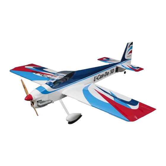
Wingspan: 65 in [1651mm]
Wing Area: 1072 sq in [69 dm
Weight: 7 lbs - 7 lbs 6 oz [3175 - 3345g]
Wing Loading: 15 - 15.9 oz/sq ft [46 - 48 g/dm
Length: 69.5 in [1765mm]
Engine: .61 - .91 cu in [10 - 15cc] two-stroke, .70 - .91 cu in [11 - 15cc] four-stroke
Great Planes
®
Model Manufacturing Co. guarantees this kit to be free from defects in both material and workmanship at the date of
purchase. This warranty does not cover any component parts damaged by use or modification. In no case shall Great Planes' liability
exceed the original cost of the purchased kit. Further, Great Planes reserves the right to change or modify this warranty without notice.
In that Great Planes has no control over the final assembly or material used for final assembly, no liability shall be assumed nor
accepted for any damage resulting from the use by the user of the final user-assembled product. By the act of using the user-assembled
product, the user accepts all resulting liability.
If the buyer is not prepared to accept the liability associated with the use of this product, the buyer is advised to return this
kit immediately in new and unused condition to the place of purchase.
READ THROUGH THIS MANUAL BEFORE
STARTING CONSTRUCTION. IT CONTAINS
IMPORTANT WARNINGS AND INSTRUCTIONS
CONCERNING THE ASSEMBLY AND USE OF
THIS MODEL.
© Copyright 2002
INSTRUCTION MANUAL
Almost Ready to Fly
2
]
2
]
A. R. F.
WARRANTY
1610 Interstate Drive Champaign, IL 61822
(217) 398-8970, Ext 2
airsupport@greatplanes.com
GPMZ0276 for GPMA1270 V1.0
™
Advertisement
Table of Contents

Related Manuals for GREAT PLANES U-Can-Do 3D


Summary of Contents for GREAT PLANES U-Can-Do 3D
-
Page 1: Instruction Manual
READ THROUGH THIS MANUAL BEFORE STARTING CONSTRUCTION. IT CONTAINS IMPORTANT WARNINGS AND INSTRUCTIONS 1610 Interstate Drive Champaign, IL 61822 CONCERNING THE ASSEMBLY AND USE OF (217) 398-8970, Ext 2 THIS MODEL. airsupport@greatplanes.com © Copyright 2002 GPMZ0276 for GPMA1270 V1.0... -
Page 2: Table Of Contents
Hardware and Accessories ..........3 aerobatics or for great Sunday fun flying. With a powerful, Covering Accessories............4 high torque 4-stroke such as an OS .91, the U-CAN-DO 3D Adhesives and Building Supplies ........4 provides exceptional slow speed and below-stall-speed Optional Supplies and Tools..........4 (3D) aerobatic performance. -
Page 3: Decisions You Must Make
AMA (Academy of Model Aeronautics). AMA membership is required to fly at AMA sanctioned clubs. There Engine notes: The U-Can-Do 3D will hover on all of the are over 2,500 AMA chartered clubs across the country. recommended engines. The engines on the lower end of the... -
Page 4: Covering Accessories
Frequently you can study photos in following steps CA Debonder (GPMR6039) to get another view of the same parts. CA Accelerator (GPMR6034) Milled Fiberglass (GPMR6165) • The U-CAN-DO 3D is factory-covered with Top Flite Microballoons (TOPR1090) MonoKote film. Should repairs ever be required, MonoKote ®... -
Page 5: Kit Contents
Kit Contents list on this page. Great Planes Product Support: Phone: (217) 398-8970 Fax: (217) 398-7721 E-mail: airsupport@greatplanes.com Kit Contents (Photographed) 1 Fiberglass Cowl 5 Stab and Elevators 9 Fuel Tank with Hardware... -
Page 6: Ordering Replacement Parts
ORDERING REPLACEMENT PARTS To order replacement parts for the Great Planes U-CAN-DO 3D ARF, use the order numbers in the Replacement Parts List that follows. Replacement parts are available only as listed. Not all parts are available separately (an aileron cannot be purchased separately, but is only available with the wing kit). -
Page 7: Preparations
PREPARATIONS 1. If you have not yet done so already, remove the major parts of the kit from the box (wings, fuse, wheel pants, cowl, tail parts, etc.) and inspect them for damage. If any parts are damaged or missing, contact Product Support at the address or telephone number on page 5. -
Page 8: Install The Aileron Servos And Pushrods
6. Separate the ailerons from the wing and take out all the hinges. 10. Apply six drops of thin CA to the top and bottom of each hinge. Do not use CA accelerator. After the CA has fully hardened, test the hinges by pulling on the ailerons. 7. - Page 9 3. Pull the center of the string out of the servo hole in the wing. It might take a little fishing to get it out. Take your time. Use the string to pull the servo wire through the wing, being careful to not pull the string loose from the other end taped in the wing.
-
Page 10: Mount The Wing To The Fuselage
12. Slide a silicone retainer over the two servo wires so they won’t fall back into the wing. Mount the Wing to the Fuselage 1. Mount the wing to the fuse with the two 1/4-20 x 2" [51mm] nylon bolts. 9. -
Page 11: Build The Fuselage
BUILD THE FUSELAGE Mount the Stab and Fin 4. Use a #11 blade to remove the false fin from the fin slot. Note: It may be necessary to pry up slightly on the front of the fin fillet to remove it. 1. - Page 12 How to cut covering from balsa. To avoid cutting into the balsa, use a soldering iron instead of a hobby knife to cut the covering. The tip of the soldering iron doesn't have to be sharp, but a fine tip does work best. Allow the iron to heat fully.
-
Page 13: Mount The Wheel Pants & Landing Gear
the bottom edge. Use a high-speed rotary tool with a cutting bit or a hobby knife to cut a 1/2" [13mm] hole centered on the mark. 12. Trim the two bolt holes in the stab covering. Bolt the stab and stab fillet in place, using the two 6-32 x 3/4" [19mm] SHCS. - Page 14 5. Drill 3/32" [2.4mm] holes through the landing gear 8. Drill two 1/16" [1.6mm] holes through the pant using diagonally on both sides of the axle nut. the holes in the gear as a guide. 9. Fasten the wheel pants to the landing gear with two #2 x 3/8"...
-
Page 15: Mount The Engine
Mount the Engine 5. Use small clamps or another method to temporarily secure the engine to the mount with the back plate of the spinner 5-7/8" [150mm] from the firewall. Use the Great 1. Draw a vertical line on the firewall using the embossed Planes Dead Center ™... - Page 16 9. Use the filler valve mount from a Great Planes Handy Mounts 2. Hold a ruler to the fuse centered on one of the cowl set (GPMQ6000), or fashion a mount from 1/8" [3mm] plywood mounting blocks. Use a felt-tip pen to draw a line directly (not included) for the fuel filler valve.
-
Page 17: Install The Tank
12. Cut out the holes in the cowl with a high-speed rotary tool and a small cutting bit. 2. Arrange the stopper and tubes as shown in the photo, then insert them into the tank. Tighten the screw to expand the stopper, thus sealing the tank. -
Page 18: Final Assembly
FINAL ASSEMBLY Install the Remaining Servos 4. Make a mark on the bottom L.E. of each elevator 1/2" [13mm] from the inboard edge of each elevator. Position the control horn centered over the mark. Mark the hole locations on the elevator. 1. - Page 19 7. Thread a clevis 25 turns onto one end of each of the three 12" [305mm] pushrods. Slip a silicone retainer over the clevises. 8. Make three one-arm servo arms. Enlarge the holes in the arm with a Hobbico Servo Horn Drill (or a #48 or 5/64" (2mm) drill bit) so the pushrod will fit.
-
Page 20: Mount The Canopy
Mount the Canopy 1. Use curved-tip scissors to cut out the canopy along the cut line. True the edges by sanding with medium-grit sandpaper. 16. Route the fuel lines as needed and mount the cowl, prop, muffler and spinner. 2. Place the canopy on the cockpit. Use a fine-point felt-tip pen to lightly trace the outline of the canopy onto the fuse. -
Page 21: Apply The Decals
Flying your model at these throws will provide you with the greatest chance for successful first flights. If, after you have become accustomed to the way the U-CAN-DO 3D flies, you would like to change the throws to suit your taste, that is fine. -
Page 22: Balance The Model Laterally
At this stage the model should be in ready-to-fly condition Note: Do not rely upon the adhesive on the back of the lead with all of the systems in place including the engine, landing weight to permanently hold it in place. Over time, fuel and gear, covering and the radio system. -
Page 23: Balance Propellers
Balance Propellers ENGINE SAFETY PRECAUTIONS Failure to follow these safety precautions may result in severe injury to yourself and others. Keep all engine fuel in a safe place, away from high heat, sparks or flames, as fuel is very flammable. Do not smoke near the engine or fuel;... -
Page 24: Radio Control
To help avoid this, a checklist is The U-Can-Do 3D is a great-flying model that flies smoothly provided to make sure these important areas are not and predictably. The U-Can-Do 3D does not, however, overlooked. -
Page 25: Takeoff
Most models take an enormous amount of work to keep the model stationary in a hanger, but the unique design of U-Can-Do 3D helps lock it solid in For reassurance and to keep an eye on other traffic, it is a position and torque roll and hang with relative ease. -
Page 26: Performance Settings
Larger than stock servo arms are highly recommended for in one spot. I do not recommend a 120 4-stroke or larger getting the 3D throws from the U-Can-Do 3D. Do not move engine if performance aerobatics are desired. the pushrods in on the control horns to get the increased throw, as doing this intensifies any play in the system. - Page 27 OTHER ITEMS AVAILABLE FROM GREAT PLANES Futaba ® S9151 Digital Rudder Servo (FUTM0211) Stock # FUTJ85** Length: 1.5 in 9CAF Width: 0.75 in R148DF Height: 1.4 in Servos (4) S3004 Weight: 1.75 oz Tx NiCd 700mAh Torque: 131.9 oz/in (4.8V) Rx NiCd 600mAh Speed: 0.19 sec @ 60°...
- Page 28 BUILDING NOTES Kit Purchased Date: _______________________ Date Construction Finished: _________________ Where Purchased:_________________________ Finished Weight: __________________________ Date Construction Started: __________________ Date of First Flight: ________________________ FLIGHT LOG...
Need help?
Do you have a question about the U-Can-Do 3D and is the answer not in the manual?
Questions and answers