Table of Contents
Advertisement
Quick Links
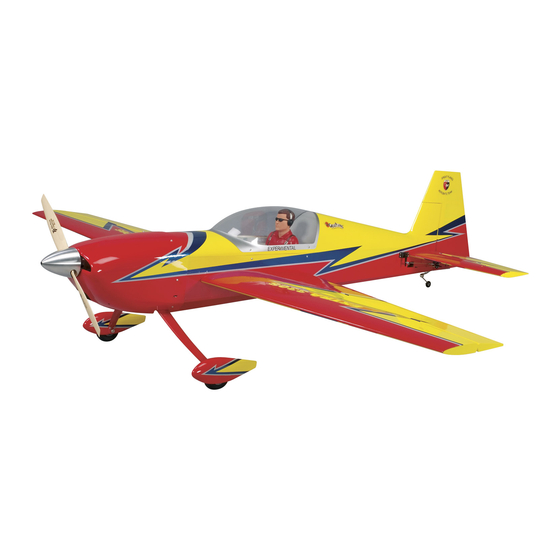
Wingspan: 79.5 in [2025mm]
2
Wing Area: 1209 in
[77.9dm
Weight: 13.5 – 15.5 lbs [6125 – 7030g]
2
Wing Loading: 26 – 29 oz/ft
[79 – 90g/dm
Length: 78 in [1980mm]
Radio:
4 to 5-channel, six to seven servos
Engine: 1.50 – 1.80 cu in [25 – 29cc] two-stroke,
1.80 – 2.10 cu in [29 – 34cc] four-stroke,
1.90 – 2.60 cu in [31 – 43cc] gas
Electric Motor: 2.5 in [63mm] dia., 2772 W, 100A ESC
Great Planes
®
Model Manufacturing Co. guarantees this kit to be free from defects in both material and workmanship at the date of purchase.
This warranty does not cover any component parts damaged by use or modifi cation. In no case shall Great Planes' liability exceed the
original cost of the purchased kit. Further, Great Planes reserves the right to change or modify this warranty without notice.
In that Great Planes has no control over the fi nal assembly or material used for fi nal assembly, no liability shall be assumed nor accepted
for any damage resulting from the use by the user of the fi nal user-assembled product. By the act of using the user-assembled product,
the user accepts all resulting liability.
If the buyer is not prepared to accept the liability associated with the use of this product, the buyer is advised to return this kit
immediately in new and unused condition to the place of purchase.
To make a warranty claim send the defective part or item to Hobby Services at the address below:
Include a letter stating your name, return shipping address, as much contact information as possible (daytime telephone number, fax
number, e-mail address), a detailed description of the problem and a photocopy of the purchase receipt. Upon receipt of the package
the problem will be evaluated as quickly as possible.
READ THROUGH THIS MANUAL BEFORE
STARTING CONSTRUCTION. IT CONTAINS
IMPORTANT INSTRUCTIONS AND WARNINGS
CONCERNING THE ASSEMBLY AND USE OF
THIS MODEL.
Entire Contents © Copyright 2007
INSTRUCTION MANUAL
2
]
2
]
3002 N. Apollo Dr., Suite 1
Champaign, IL 61822 USA
WARRANTY
Hobby Services
Champaign, Illinois
(217) 398-8970, Ext 5
airsupport@greatplanes.com
GPMZ1413 for GPMA1413 V1.0
Advertisement
Table of Contents

Related Manuals for GREAT PLANES EXTRA 330S


Summary of Contents for GREAT PLANES EXTRA 330S
-
Page 1: Instruction Manual
Further, Great Planes reserves the right to change or modify this warranty without notice. In that Great Planes has no control over the fi nal assembly or material used for fi nal assembly, no liability shall be assumed nor accepted for any damage resulting from the use by the user of the fi... -
Page 2: Table Of Contents
“ARFs-GLOW.” Scroll down the ASSEMBLE THE FUEL TANK ..........19 Glow Engines ..............19 page and click on “Extra 330S 1.60 ARF.” If there is new Gas Engines ................ 19 technical information or changes an “Important! TECH Mount the Fuel Tank ............ -
Page 3: Imaa
8. While this kit has been fl ight tested to exceed normal use, if the plane will be used for extremely high stress fl ying, such The Great Planes Extra 330S 1.60 ARF qualifi es as a as racing, or if an engine larger than one in the recommended “giant-scale”... -
Page 4: Decisions You Must Make
❏ (2) Packages Du-Bro #813 1/8" [3.2mm] I.D. fuel line barbs (DUBQ0670) This is a partial list of items required to fi nish the Extra 330S ❏ At least six small, nylon ties (available from home 1.60 ARF that may require planning or decision making improvement, automotive or hardware stores) ❏... -
Page 5: Electric Motor Accessories
Batteries for Electric Motor Power discharge connector (that is the plug that connects to the ESC). LiPo batteries should be charged through the balance connector via a LiPo cell balancer such as a Great Planes ElectriFly Equinox ™ (GPMM3150). One Equinox for each There may be many different battery combinations available battery to be charged simultaneously will be required. -
Page 6: Radio Equipment
Required Hardware & Accessories higher-precision servos available if this is your preference. ❏ The elevator servos in the Great Planes Extra 330S 1.60 Suitable propeller and spare propellers ❏ ARF move in opposition, so if the radio you will be using is not R/C foam rubber (1/4"... -
Page 7: Optional Supplies & Tools
Replacement Parts List. Payment by credit card or personal check only; no C.O.D. A pilot fi gure is not included with this model. But Great Planes offers a line of 1/4-scale Sport pilot fi gures: (GPMQ9010–red, If additional assistance is required for any reason contact Product Support by e-mail at productsupport@greatplanes.com, or... -
Page 8: Kit Inspection
If any parts are missing or are not of acceptable quality, or if you need assistance with assembly, contact Product Support. When reporting defective or missing parts, use the part names exactly as they are written in the Kit Contents list. Great Planes Product Support: 3002 N Apollo Drive, Suite 1 Champaign, IL 61822 Telephone: (217) 398-8970, ext. -
Page 9: Shrink The Covering
SHRINK THE COVERING ❏ 1. Examine the airframe for wrinkles in the covering or areas where the covering isn’t adhered to the structure. Where necessary, use a covering iron with a protective covering sock to shrink any wrinkles and get the covering bonded to the framework–use an iron temperature setting around 250°... -
Page 10: Hook Up The Ailerons
Harden the screw holes with a few drops of thin CA. Allow the CA to harden, then mount the servos again. ❏ 5. Great Planes large-scale 1.5" [38mm] single-sided servo arms with adapters (GPMM1105) are shown in this manual. Select the plastic servo arm adapters for the servos you will be using –... -
Page 11: Assemble The Fuselage
❏ 7. Mount the servo arms to the aileron servos using the appropriate servo adapters–the arms “point” toward the wing tips. Note: If the screws that hold on the servo arms have machine threads that go into metal output shafts in the servos, use a drop of threadlocker on the screws before mounting the arms. - Page 12 ❏ 2. Place each servo in its opening and drill 1/16" [1.6mm] holes for the mounting screws. ❏ 5. Once you have the trailing edge centered, stick large T-pins through the trailing edge tightly against both sides of the fuselage. This will keep the trailing edge centered while rotating the leading edge in the next step.
- Page 13 Suggestion: Access to the wing bolts will be much easier with a Great Planes 4-in-1 Installation Tool (GPMR8035). ❏ 10. Take the T-pins out of the stab and take the stab out This will be especially helpful when you get to the fl...
-
Page 14: Hinge The Elevators & Rudder
❏ stab, add any weight that may have been necessary to align 2. The same as was done for the servo extension wires on the stab with the wing, wipe away more epoxy that may have the aileron servos, secure the connections with 3" [75mm] dripped out, check the alignment once more, then do not pieces of heat-shrink tubing cut in half. -
Page 15: Hook Up The Elevators
pushrods. Hold the horns to the rudder and drill 3/32" [2.4mm] the aileron pushrods to solder large metal solder clevises to holes 1/2" [13mm] deep for the mounting screws – same as the ends of the elevator pushrods. the aileron horns, the rudder horns should be mounted all the ❏... -
Page 16: Hook Up The Pull/Pull Rudder Cables
transmitter and receiver. Connect the servo arms on the rudder servos with the rudder pushrods and four 4-40 x 1/4" [6.4mm] SHCS. Turn off the radio. Hook Up the Pull/Pull Rudder Cables ❏ 4. Remove the plywood servo arm drilling template. Keeping the servo wheel in the same orientation as when it ❏... - Page 17 ❏ 12. Mount the other cable to the other side of the rudder the same way. ❏ 13. Connect another 4-40 clevis, a 4-40 nut and a silicone retainer to another threaded coupler. ❏ ❏ 5. Thread a 4-40 nut and a 4-40 clevis onto the threaded coupler on the cable.
-
Page 18: Mount The Tail Gear
Fuji-Imvac BT-43EI-2 gas engine and the other is for both the included Great Planes 1.20 to 1.80 adjustable engine mount for glow engines and the ElectriFly Brushless Motor Mount for extra large motors (GPMG1265 –... -
Page 19: Assemble The Fuel Tank
(or the backplate of the spinner) is 6-3/4" [170mm] from the fi rewall. Use a ™ Great Planes Dead Center Hole Locator or a drill bit to mark the engine mounting holes into the engine mount. -
Page 20: Mount The Fuel Tank
Insert the stopper so the vent tube will be at the top of the tank. Then tighten the screw to squish the stopper and seal the tank. Shake the tank to make sure the clunks can move around and the fuel lines are not too long. If necessary, remove the stopper and shorten the lines. - Page 21 ❏ 6. Plan the fuel line setup thinking about how you will be ❏ 4. Securely glue the plywood fuel tank tray into position. fueling the model, where the fueling and vent/pressure lines will be located, how to guide the fuel lines around the muffl er and engine and where the lines will go through.
-
Page 22: Hook Up The Throttle
Hook Up the Throttle FORWARD RADIO TRAY FORWARD RADIO TRAY AFT RADIO TRAY ❏ 3. Securely epoxy both 3/8" x 3/8" x 4" [10 x 10 x 100mm] radio tray mounting rails inside the fuselage for the location you will be using. The rails should be centered across the horizontal members and approximately 1/8"... -
Page 23: Glow Engine Throttle Hookup
❏ 2. Hook up the throttle using the hardware listed below. Glow engine throttle pushrod hardware: ❏ 2-56 x 36" [910mm] wire pushrod ❏ 3/16" x 36" [4.8 x 910mm] gray pushrod guide tube On the servo end: ❏ brass screw-lock pushrod connector ❏... -
Page 24: Gas Engine Throttle Hookup
On the engine end: ❏ Gas Engine Throttle Hookup 2-56 x 1" [25mm] threaded rod ❏ nylon ball link ❏ 2-56 ball link ball ❏ ❏ 1. If using a Fuji-Imvac BT-43EI-2, use an extended 3/16" 2-56 nut [4.8mm] drill bit or a 3/16" [4.8mm] brass tube sharpened on the end to drill a hole for the gray pushrod guide tube where shown in the following photo. - Page 25 determine where to mount the battery, module and switch alternate set of mounting tab sides that don’t have the cut- would be to connect all the wires and see how much distance outs should you decide to remove the mounting tabs from between them is required.
-
Page 26: Mount The Electric Motor
Mount the Electric Motor ❏ 1. If you haven’t yet done so, mount the prop adapter to the electric motor using threadlocker on the threads. ❏ 4. Glue together the plywood parts for whichever ESC mounting platform that best fi ts your ESC. There are two mounting platforms included–one is wider than the other. - Page 27 ❏ 4. Temporarily mount the battery pack to the mounting plate with the straps. Test fi t the assembly into the fuselage to make sure everything fi ts. Make adjustments as necessary. ❏ 5. Use 30-minute epoxy to securely glue the battery tray ❏...
-
Page 28: Final Assembly
FINAL ASSEMBLY Mount the Cowl At this point your power system installation–whether it’s gas, glow or electric–should be complete. For electric motors the ESC and motor should be mounted and battery installation should be fi nalized. For gas or glow systems, the engine should be mounted and the fuel tank should be installed with all the lines connected. - Page 29 ❏ ❏ 4. Make two templates as shown from manila folder 6. Fit the cowl onto the fuselage over the engine. Use material or other medium card stock. Place the canopy the prop nut or the engine bolt to mount the cowl centering hatch on the fuselage, then tape the templates to the canopy jig to the engine/motor–if necessary, use a cardboard tube hatch so the holes in the templates align with the marks on...
- Page 30 ❏ 11. Use coarse sandpaper to roughen the inside of the cowl around each screw hole. Use medium CA or epoxy to glue the 1/32" [1mm] plywood screw hole reinforcements inside the cowl centered on each hole. ❏ 13. If you haven’t yet done so, cut the air inlet hole in the front of the cowl below the spinner.
-
Page 31: Mount The Pilot
Mount the Pilot ❏ 1. Remove the six screws that hold on the canopy. Add a drop of thin CA to each screw hole that the screws came from. ❏ 2. Test fi t the pilot (not included) in the cockpit with the canopy to make sure he fi... -
Page 32: Mount The Canopy Hatch
fi ne-point felt-tip pen to mark the screw hole in the outer Mount the Canopy Hatch wheel collar onto the axle. ❏ 1. Use a sharp hobby knife to cut the covering from the four canopy hatch screw holes in both sides of the fuselage. ❏... -
Page 33: Apply The Decals
This is how to connect three batteries in Series: decals the same way. GET THE MODEL READY TO FLY If you’ve assembled your Extra 330S 1.60 ARF with a glow or gas engine, skip directly to “Check the Control Directions” on page 34. -
Page 34: Check The Control Directions
Check the Control Directions ❏ 1. IMPORTANT: If your Extra 330S 1.60 ARF is powered by an electric motor, remove the propeller if you haven’t done so already. ❏ 1. Use a small box or something similar to prop up the ❏... -
Page 35: Balance The Model (C.g.)
fi rst fl ights. If, after you have become accustomed to the way the Extra 330S 1.60 ARF fl ies, you would like to change the throws to suit your taste, that is fi ne. However, too much control throw could make the model diffi... -
Page 36: Balance The Model Laterally
Identify Your Model We use a Top Flite Precision Magnetic Prop Balancer (TOPQ5700) in the workshop and keep a Great Planes No matter if you fl y at an AMA sanctioned R/C club site or Fingertip Prop Balancer (GPMQ5000) in our fl ight box. -
Page 37: Electric Motor & Engine Safety Precautions
The following precautions apply only to electric- ELECTRIC MOTOR & ENGINE powered models. SAFETY PRECAUTIONS • Always remove the LiPo battery from the plane before charging. The following precautions apply both to electric motors and gas and glow engines. Failure to follow •... -
Page 38: Check List
❏ 6. Use thread-locking compound to secure critical fasteners The Extra 330S 1.60 ARF is a great-fl ying model that fl ies such as the set screws on the wheel collars, screw-lock smoothly and predictably. The Extra 330S 1.60 ARF does pushrod connectors, etc. -
Page 39: Takeoff
The best thing to do when fl utter is Take it easy with your Extra 330S 1.60 ARF for the fi rst detected is to slow the model immediately by reducing few fl... -
Page 40: 3D Flying
are on the desired rates (high/low rates). A fl ight plan greatly model from being pulled downwards). As the model fl attens reduces the chances of crashing your model just because of out, add power to pull the model around. Many models will poor planning and impulsive moves. - Page 41 OTHER ITEMS AVAILABLE airspeed. The rudder is now used to turn the model. This FROM GREAT PLANES maneuver will take some practice as there are a lot of small corrections made to keep most planes in the maneuver.
- Page 42 Extra 330S 3D ARF weight and vibration. FJIG0144 Performance equals fun – and the Extra 330S EP ARF offers plenty of both! What’s more, performance can be tailored to Fuji-Imvac is not related to the original Fuji Engines sold by Mecoa.
- Page 43 – before discharging them at custom rates and then repeating the cycle up to 10 times. GPMM3150 ElectriFly by Great Planes 3200mAh Power Series LiPo Battery with Balance Connector Ideal for scale aircraft, bigger sport aerobats, 3D planes, and larger electric models, the Power Series 3200mAh LiPo pack enables you to enjoy the benefits of balancing.
- Page 44 BUILDING NOTES Kit Purchased Date: ___________________________ Date Construction Finished: _______________________ Where Purchased: ____________________________ Finished Weight: _______________________________ Date Construction Started: _____________________ Date of First Flight: ______________________________ FLIGHT LOG...
Need help?
Do you have a question about the EXTRA 330S and is the answer not in the manual?
Questions and answers