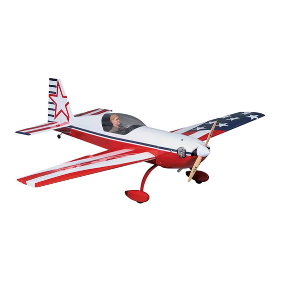
GREAT PLANES Extra 300S Instruction Manual
Aerobatic .60-size sport-scale kit
Hide thumbs
Also See for Extra 300S:
- Instruction manual (24 pages) ,
- Instruction manual (48 pages) ,
- Instruction manual (48 pages)
Table of Contents
Advertisement
Great Planes Model Manufacturing Co. guarantees this kit to be free from defects in both material and
workmanship at the date of purchase. This warranty does not cover any component parts damaged by use or
modification. In no case shall Great Planes' liability exceed the original cost of the purchased kit. Further, Great
Planes reserves the right to change or modify this warranty without notice.
In that Great Planes has no control over the final assembly or material used for final assembly, no liability shall be
assumed nor accepted for any damage resulting from the use by the user of the final user-assembled product. By the
act of using the user-assembled product, the user accepts all resulting liability.
If the buyer is not prepared to accept the liability associated with the use of this product, the buyer is advised
to return this kit immediately in new and unused condition to the place of purchase.
While this kit has been flight tested to exceed normal use, if the plane will be used for extremely high stress flying, such
as racing, the modeler is responsible for taking steps to reinforce the high stress points.
READ THROUGH THIS MANUAL BEFORE
STARTING CONSTRUCTION. IT CONTAINS
IMPORTANT WARNINGS AND INSTRUCTIONS
CONCERNING THE ASSEMBLY AND USE OF
THIS MODEL.
© Copyright 2004
INSTRUCTION MANUAL
WARRANTY
P.O. Box 788
Urbana, IL 61803
WWW.GREATPLANES.COM
(217) 398-8970
EXT6P03 V1.2
Advertisement
Table of Contents

Related Manuals for GREAT PLANES Extra 300S


Summary of Contents for GREAT PLANES Extra 300S
-
Page 1: Instruction Manual
Planes reserves the right to change or modify this warranty without notice. In that Great Planes has no control over the final assembly or material used for final assembly, no liability shall be assumed nor accepted for any damage resulting from the use by the user of the final user-assembled product. By the act of using the user-assembled product, the user accepts all resulting liability. -
Page 2: Table Of Contents
Flying ......................45 elevator or aileron throw to put the Extra through its paces. Takeoff .....................45 When you have a feel for your Extra 300S, the throws can Flying ....................46 Landing ....................46 be increased to high rates (illustrated in the instructions) to 2-View Drawing ..................47... -
Page 3: Precautions
We hope you enjoy building and flying your Great Planes There are several engines that will work well in your Extra 300S as much as we did flying the prototypes. Extra 300S, but for unlimited performance we recommend a hot 2-stroke such as an O.S. -
Page 4: Building Supplies And Tools
Drill bits: 1/16", 5/64", 3/32", 7/64", 1/8", 5/32", #18 or 11/64", 3/16", #10 or 13/64", 7/32", 1/4", 17/64" Types of Wood On our workbench, we have three 11" Great Planes Easy-Touch Bar Sanders, equipped with 80, 150 and 220-grit sandpaper. This setup is all that is required for almost any sanding task. -
Page 5: Building Notes
There are two types of screws used in this kit: 1. Unroll the plan sheet. Reroll the plan sheet inside out to make it lie flat. Place wax paper or a Great Planes Plan Sheet metal screws are designated by a number and a... -
Page 6: Die-Cut Patterns
DIE-CUT PATTERNS... - Page 7 DIE-CUT PATTERNS...
-
Page 8: Build The Tail Surfaces
You may remove the stabilizer and elevator drawing from the wing plan by cutting along the dashed line. Don’t forget to cover the plan with a Great Planes Plan Protector so the glue won’t stick to the plan. A. Use a metal straightedge as a guide to trim one edge of both sheets. -
Page 9: Build The Stab
3. Fit and glue the 3/16" x 3/16" x 14" basswood rear 1/16" x 3" x 30" balsa sheets stab spar to the rear of the stab center. Cut down the middle to make two 4-1/2" sheets. 2. Cut the sheet you have made in half making two sheets 4-1/2"... -
Page 10: Elevator Building Sequence
Fin Building Sequence Note: Because it is not necessary to build on the fuse plans we reduced them to 75% so that they are easier to use as a reference while building the fuse. Make sure to build the fin and rudder over the full-size drawing, not the reduced plan. -
Page 11: Rudder Building Sequence
Rudder Building Sequence 2. Cut the hinge slots in the elevator and stabilizer using a #11 blade. Begin by carefully cutting a very shallow slit at the hinge location to accurately establish the hinge 1. Make the LE using a 5/16" x 1/2" x 14" balsa stick slot. -
Page 12: Build The Wing
1. Tape the left wing plan to your flat work surface, 5. Glue R1, R2 and R2A in place using a leftover and cover the wing drawing with Great Planes Plan piece of 1/16" ply as a spacer to locate the ribs 1/16" away Protectors (so you won’t glue the wing to the plan!). - Page 13 6. From a 3/32" x 3" x 24" balsa sheet, make shear 10. Glue a piece of 1/16" x 3" x 36" balsa sheet on webs to fit from ribs R3 through R8, with an additional web the TE of the wing, aligning the LE of the sheeting with the aft of the spars between R3 and R4.
-
Page 14: Sheet The Center Section
14. Carefully lift the sheeting away from the ribs, then 5. Glue the 7" balsa middle center sheet in place. apply a bead of medium or thick CA to the top of each rib and the sub LE. Working quickly, pull the sheeting forward as you press it down to the ribs and the sub LE. - Page 15 4. Glue a piece of 1/16" balsa to the servo mount support, aligning it with the top of the sub rib and the top of R6 as shown in the photo. 9. Cut the TE sheeting along the outside edge of R4 from the aft edge of the spar to the aft edge of the sheeting.
-
Page 16: Join The Wing Panels
13. From the 3/8" x 2" x 8" balsa block, fit and glue the wing bolt filler between the TE of R1 and R2. Sand the wing bolt filler to the contour of ribs R1 and R2. 18. Using a razor saw and a hobby knife, trim the spacer tabs off of R1, R2 and R2A. - Page 17 Note: Make sure the “V’s” on the dowel plates are both on the same side. 3. Place a Great Planes Plan Protector under the center of the wing to catch excess epoxy. When satisfied with the fit, glue the die-cut 1/16" ply dihedral braces (DB) to the...
-
Page 18: Sheet The Top Of The Wing
5. Lift the wing off the building board and trim the sheeting the same as you did on the bottom of the wing. Save the bigger piece for the aileron. 6. Repeat steps 2-5 for the other wing half. 11. Trim the sub LE and the sheeting flush with the sub ribs and the dowel plate. - Page 19 16. Sand the TE of the wing square. 11. Sheet the center of the wing with the remaining six pieces of center sheeting. 12. Use the two remaining 1/16" x 1/4" x 36" balsa sticks to cap strip all the exposed ribs. 13.
-
Page 20: Build The Ailerons
21. Sand the LE to the airfoil shape shown on the plans. 25. Sand the root caps and tip caps to match the shape of the wing. 26. Slightly round one end of both of the 1/4" x 2-1/2" wing dowels. 22. - Page 21 2. Find one of the 1/16" balsa sheets that you have 7. Using another 1/16" balsa sheet that you saved saved from the TE sheeting of the wing, and trim it to 2" from the TE sheeting, glue the bottom aileron sheeting in wide.
-
Page 22: Build The Fuselage
4. Use medium CA to accurately glue the fuse doubler BUILD THE FUSELAGE (part #2) to the inside of the right fuselage side. Do not glue former 7 in place at this time. 5. Glue the left fuselage doubler to the inside of the left Assemble the Fuselage fuselage side in the same manner. -
Page 23: Assemble The Fuselage
5. Glue former 7 (part #7) in place the same way. 1. Draw a straight line on your work surface 45" long. Cover this line with Great Planes Plan Protector. Note: These next three steps should be completed together and assembled quickly. -
Page 24: Mount The Wing To The Fuselage
9. Glue the rest of the fuse sides to the fuse top. 13. Glue former 11 (part #11) in place. 14. Sand the 1/4" x 1-1/4" x 5-1/2" birch ply wing bolt block to fit precisely in the slots in the fuse doublers. Note: It is very important that the fit of the wing bolt block be precise. - Page 25 4. Center the wing side to side, leaving equal space between the fuse sides and the wing at the leading edge. 10. Cover the area of the belly pan with a Great Planes 5. Making sure to keep the wing centered and in the Plan Protector or waxed paper.
- Page 26 15. Glue the die-cut 1/8" ply belly pan spines (part #24) in place with thin CA. 16. Glue the die-cut 1/8" ply wing bolt plate (part #21) in place. 13. Remove the belly pan from the wing and glue the die-cut 1/8"...
-
Page 27: Finish The Bottom Of The Fuselage
20. Mount the wing to the fuse with the one bolt and Finish the Bottom of the Fuse repeat steps 17-19 to drill and tap the other bolt hole. 1. Unpin the fuse from your work surface. 2. Double-check all of the glue joints. Reinforce them with medium CA as needed. - Page 28 12. Fit the die-cut 1/8" ply forward landing gear former (part #15) and the die-cut 1/8" ply forward fuse bottom (part #16) in place. Clamp the fuse sides tight against the forward landing gear former and glue both pieces in place. 7.
-
Page 29: Build The Front Fuselage Deck
16. Center the landing gear on the fuse and drill two 1/8" 21. Glue the die-cut 1/8" ply stab base (part #5) in holes through the landing gear rails. Mount the landing place with medium CA. gear in place with the #8 x 5/8" truss head screws. Build the Front Fuselage Deck 17. -
Page 30: Mount The Stabilizer To The Fuselage
model and see if the stab is parallel with the wing. If necessary, 4. Cut the 1/16" x 4" x 24" balsa sheet in half, making use your bar sander to make adjustments by sanding the two 12" long pieces. Edge glue them together. stab base until the stab is in alignment with the wing. -
Page 31: Mount The Fin
Mount the Fin 2. Use a square to position the die-cut 1/8" ply turtle deck formers (part #’s 29 and 30) vertically, 90° to the fuse top. Note: Part #29 glues to the front side of part #9, 1. Fit the fin in place aligning it with a straightedge held not on top of it. -
Page 32: Mount The Engine & Tank Tray
8. Sand a taper on the top rear 5" of the sheeting. Mount the Engine & Tank Tray 1. Cut the “spreader bar” from the supplied Great Planes engine mount, then use a hobby knife to remove any flashing left over from the molding process so the halves fit together well. -
Page 33: Install The Servos & Make The Pushrods
CA, aligning it with part #27. 2. Use your servos to locate the 3/8" x 1/2" x 5" basswood forward servo rail and glue in place. 5. Use the Great Planes Dead Center Engine Mount ™ Hole Locator (GPMP8130) to mark the locations of the bolt holes. - Page 34 5. Bend and cut the 36" throttle pushrod wire (the one 8. Insert the elevator pushrods into the pushrod tubes. that is threaded on one end) to fit your engine installation, Position the control horns on the elevators as shown in the using the drawing on the fuselage plan as a guide.
- Page 35 12. Connect the pushrod to the servo with a nylon Faslink. Note: If necessary, enlarge the hole in the servo arm with a 5/64" drill bit (or a #48 bit for precision). Let the pushrod locate the servo (left to right), in the servo tray, then screw the elevator servo in place.
-
Page 36: Assemble The Wheel Pants
23. Connect the clevis to the control horn. Center the aileron and the servo arm. Mark the pushrod where it crosses the servo arm. Bend the pushrod and connect it to 2. Use your bar sander to carefully true the edges of the servo arm with a nylon Faslink. - Page 37 B. Insert the 8-32 x 1-1/2" bolt “axle” part way into the wheel through the 1/4" hole in the outside of the wheel pant. Hold an 8-32 nut with a needle nose pliers inside the wheel pant. Use a 9/64" hex wrench to screw the axle through the nut and through the wheel pant mount.
-
Page 38: Assemble The Cowl
14. After the filler cures, wet sand the wheel pants with 5. Use 30-minute epoxy to glue a 1" strip of glass cloth 400-grit sandpaper to prepare them for primer. across the glue joint inside the front of the cowl on both sides. Assemble the Cowl 1. -
Page 39: Balance The Model Laterally
This step is optional but will enhance the scale 3/32" hole through the cowl and the fuse side at one of the appearance of your Extra 300S. locations shown on the plan. Using a #4 x 1/2" screw, attach the cowl to the fuse. Do the same for the other three 2. -
Page 40: Cover The Model With Monokote Film
Suggested Covering Sequence COVER THE MODEL WITH MONOKOTE FILM ™ Fuselage 1. 1/4" strips at fin and stab as described 2. Aft fuse bottom 3. Forward fuse bottom Covering Technique 4. Fuse right side up to the center of the turtle deck 5. -
Page 41: Final Hookups & Checks
compatible with the clear canopy, test the paint on a the elevators to the stab, confirm that the hinges are leftover piece of canopy material. equally inserted in the elevators and the stab. Insert a small pin in the center of the hinges to keep them centered. For painting the pilot we have discovered that acrylic water base paints such as the types found at craft stores work ASSEMBLE, THEN APPLY 6 DROPS... -
Page 42: Attach The Canopy
5. Install the elevator, rudder and throttle pushrods, then install the control horns and hook them up the same way you did earlier. 6. Wrap the receiver and battery pack in at least 1/4" of foam rubber, then fit them in the location shown on the plans. -
Page 43: Balance Your Model
Extra 300S, you may wish to experiment by shifting throw. You may also use the ATV's if your transmitter has the balance up to 3/8"... -
Page 44: Balance The Propeller
Fingertip Balancer (GPMQ5000) in our flight box. Find a Safe Place to Fly Engine Safety Precautions Since you have chosen the Extra 300S we assume that you are an experienced modeler. Therefore, you should Note: Failure to follow these safety precautions may already know about AMA chartered flying fields and other result in severe injury to yourself and others. -
Page 45: Ama Safety Code (Excerpt)
2. I will not fly my model aircraft higher than approximately 400 feet within 3 miles of an airport without notifying the The Great Planes Extra 300S is a great flying semi-scale airport operator. I will give right of way to, and avoid flying sport model that flies smoothly and predictably, yet is highly in the proximity of full scale aircraft. -
Page 46: Flying
OTHER KITS AVAILABLE FROM GREAT PLANES Flying We recommend that you take it easy with your Extra 300S for the first several flights, gradually “getting acquainted” with this great sport model as your engine gets fully broken in. If you feel as though you have your hands full, keep this one thing in mind: pull back on the throttle stick to slow the model down. -
Page 47: 2-View Drawing
TWO VIEW DRAWING Use copies of this page to plan your trim scheme. -
Page 48: Flight Log
BUILDING NOTES Kit Purchased Date:________________________ Date Construction Finished: _________________ Where Purchased:_________________________ Finished Weight: __________________________ Date Construction Started: __________________ Date of First Flight: ________________________ FLIGHT LOG...
Need help?
Do you have a question about the Extra 300S and is the answer not in the manual?
Questions and answers