Table of Contents
Advertisement
Advertisement
Table of Contents

Related Manuals for Tally T2030/24


Summary of Contents for Tally T2030/24
- Page 1 T2030/24 T2030/9 T2130/24 T2130/9 Maintenance Manual Matrix Printer...
-
Page 2: Table Of Contents
Table of Contents Introduction ........1-1 Guide to Safety Inspections ....... . . 1-1 1.1.1 Guideline to Inspections . - Page 3 5.1.6 Head Flex Cable (24) ........5-10 5.1.7 Path Change Lever .
- Page 4 5.1.60 ASF HPR SW ASM ........5-99 5.1.61 Optional Tractor .
-
Page 5: Introduction
Introduction Guide to Safety Inspections Introduction Guide to Safety Turn OFF the power of the machine and unplug all the power cords before starting in- spections. Inspections Ensure that all safety requirements are satisfied. 1.1.1 Guideline to Inspections This guideline is provided to check if the machine is in a dangerous status or not. A safety mechanism or caution label is needed to prevent the owner, operators, or ser- vice personnel from sustaining injuries. - Page 6 Guide to Safety Inspections Introduction Are the following labels applied? [1] Indication of a danger spot [2] Indication of a heated-up spot Confirm during preventive maintenance that safety labels are applied at the positions shown in the figure below. Safety Labels [1] Indication of a danger spot [2] Indication of a heated-up spot * The GND mark...
-
Page 7: Overview
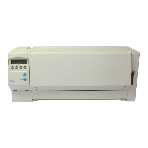
Introduction Overview Overview When attached to a network, this printer can be used as an output device to print Fonts and Graphics using the dot-matrix impact method. Paper Extension Trays Paper Tray Access Cover Operation Panel Paper Feed Knob Left Paper Guide Cut Sheet Paper Insert Guide... - Page 8 Overview Introduction Auto Sheet Feeder (ASF) Fig. 1-4: Printer With Auto Sheet Feeder (ASF) Optional Tractor Fig. 1-5: Printer With Optional Tractor Serial Interface Option Fig. 1-6: Serial Interface Option...
-
Page 9: Components Of The Printer
Introduction Components of the Printer Components of the Printer I/F Connector CA Motor LF Motor Main Option Card Logic Board Load Sensor, PE Sensor Asm, Paper Select Sensor Print Head Power Supply Sub PCB PL Operator’s Home Position Panel Sensor Fig. -
Page 10: Hardware Options
Components of the Printer Introduction 1.3.1 Hardware Options The following three items are hardware options for this printer. Auto Sheet Feeder (ASF) The ASF is a device to feed cut sheet paper, sheet by sheet, by controls from the printer. Fig. 1-8 shows the Auto Sheet Feeder (ASF). Front Cover Manual Insert Guide Auto Sheet Feeder... -
Page 11: Specifications
Specifications Specifications 9-Needle Version Specifications Specifications 9-Needle Version Printer Specifications Print head Quantity 9 needles Diameter 0.30 mm Pitch of needles 1/72 inch Copies 1 + 5 Lifetime > 200 mill. dots/pin (refurbishment is not possible) Print speed HS Draft bidirectional 360 cps at 10.0 cpi 320 cps at 12.0 cpi 400 cps at 15.0 cpi... - Page 12 Specifications 9-Needle Version Specifications Print positions T2030/T2130 80/136 characters at 10.0 cpi 96/163 characters at 12.0 cpi 120/204 characters at 15.0 cpi 136/232 characters at 17.1 cpi 160/272 characters at 20.0 cpi Line spacing 3/4/6/8/12 lpi Character size 3.20 mm high (includes descenders) 1.90 mm wide (full width characters) Character sets IBM-PC world trade and IBM-PC US trade.
- Page 13 Specifications Specifications 9-Needle Version Ribbons The standard black ribbon provides a minimum of 4 million legible draft characters before degradation occurs. Paper specification The printer handles single sheets, multipart forms and continuous sprocket forms. Single sheets may be inserted manually from the front using the cut sheet paper insert guide or automatically using the cut sheet feeder ASF.
- Page 14 Specifications 9-Needle Version Specifications Physical characteristics Noise Tractor <55 dB (A) Sheet feeder <55 dB (A) Measured with draft characters according to ISO standard 7779 in bystander position. Dimensions Approximate physical dimensions with ASF1 width (T2030) 485 mm width (T2130) 625 mm depth 245 mm...
- Page 15 Specifications Specifications 9-Needle Version Mechanical Stability Vibration Operation Transport (no pack.) on three axes on three axes Frequency range 5 Hz to 150 Hz 5 Hz to 150 Hz Acceleration ampl. 5 m/s 5 m/s Displacement ampl. 0.035 mm 0.035 mm Exposure time (total) 1.5 hours 1.5 hours...
-
Page 16: Specifications 24-Needle Version
Specifications 24-Needle Version Specifications Specifications 24-Needle Version Printer Specifications Print head Quantity 24 needles, 2 rows staggered Diameter 0.20 mm Pitch of needles 1/180 inch Copies 1 + 3 Lifetime > 200 mill. dots/pin (refurbishment is not possible) ± 7 % (depend of character matrix) Print speed Fast Draft bidirectional 330 cps at 10.0 cpi... - Page 17 Specifications Specifications 24-Needle Version Print positions T2030/T2130 80/136 characters at 10.0 cpi 96/163 characters at 12.0 cpi 120/204 characters at 15.0 cpi 136/232 characters at 17.1 cpi 160/272 characters at 20.0 cpi Line spacing 3/4/6/8/12 lpi Character size 3.20 mm high (includes descenders) 1.90 mm wide (full width characters) Character sets IBM-PC world trade and IBM-PC US trade.
- Page 18 Specifications 24-Needle Version Specifications Ribbons The printer uses a cassette fabric ribbon that can be changed by the operator. The standard black ribbon provides a minimum of 4 million (T2030/T2130) legible draft characters before degradation occurs. Paper specification The printer handles single sheets, multipart forms and continuous sprocket forms. Single sheets may be inserted manually from the front using the cut sheet paper insert guide or automatically using the cut sheet feeder ASF.
- Page 19 Specifications Specifications 24-Needle Version Physical characteristics Noise Tractor <55 dB (A) Sheet feeder <55 dB (A) Measured with draft characters according to ISO standard 7779 in bystander position. Dimensions Approximate physical dimensions with ASF width (T2030) 485 mm width (T2130) 625 mm depth 245 mm...
- Page 20 Specifications 24-Needle Version Specifications Mechanical Stability Vibration Operation Transport (no pack.) on three axes on three axes Frequency range 5 Hz to 150 Hz 5 Hz to 150 Hz Acceleration ampl. 5 m/s 5 m/s Displacement ampl. 0.035 mm 0.035 mm Exposure time (total) 1.5 hours 1.5 hours...
-
Page 21: Protective Function For Print Head Overheating
Specifications Protective Function for Print Head Overheating Protective Function for When printing is performed continuously over a long period, the print head heats up, and may cause problems. To prevent the print head from becoming too hot, this prin- Print Head Overheating ter has a function to stop the print head between lines or to print only in one direction and wait until the print head cools down. -
Page 22: Functional Description
Functional Description Activating Principles Functional Description Activating This printer can be connected to various work stations and prints data using the wire dot-matrix impact method. The interior processes of the printer are divided into the Principles Data Receiving Section, the Command Processing Section, the Print Image Creating Section, and the Mechanical Control Section. -
Page 23: Print Head
Activating Principles Functional Description PROM This is where the control program executed on the CPU is stored. The control pro- gram controls data receiving, command processing, print image creation, Operation Panel, and other respective mechanisms. Data Receiving Data sent from the work station is temporarily saved through the printer cable, byte by byte, to the Receive Buffer. -
Page 24: Carrier Drive Mechanism And Ribbon Drive Mechanism
Functional Description Activating Principles 3.1.2 Carrier Drive Mechanism and Carrier Drive Mechanism Ribbon Drive Mechanism The carrier is driven by connecting the CA Motor and the Carrier Belt together and ro- tating the CA Motor CA Motor Carrier Carrier Belt Carrier Shaft Paper Thickness Adjustment Lever... - Page 25 Activating Principles Functional Description Ribbon Drive Mechanism This mechanism feeds the ribbon in a single direction to match the carrier movement. It conveys the drive from the CA Motor, further conveys it to each gear in the Ribbon Gear Holder Assembly via the Pulley, and revolves the Ribbon Drive Gear. The Epi- cyclic Gear revolves the Ribbon Drive Gear always in one direction only regardless of the carrier movement direction.
-
Page 26: Paper Feed Mechanism
Functional Description Activating Principles 3.1.3 Paper Feed Mechanism Cut Sheet Paper is fed when the LF Motor revolves the Feed Roller. Continuous Form Feed Paper is fed when the LF Motor revolves the sprockets in the Sprocket Blocks of the tractor. The Cut Sheet Paper feeding and the Continuous Form Feed Paper feeding are alter- nated by the Path Change Lever. - Page 27 Activating Principles Functional Description Cut Sheet Paper Feeding When the Path Change Lever is at the “Cut Sheet Paper” position, the Pinch Roller (1) is pressing against the Lower Feed Roller. Therefore, the paper pinched between the rollers will be fed by the revolution of the two rollers. Continuous Form Feed Paper Feeding When the Path Change Lever is at the “Continuous Form Feed Paper”...
-
Page 28: Operation Panel
Functional Description Activating Principles 3.1.4 Operation Panel The Operation Panel consists of keys. When a key is pressed, it is recognized by the control program and its function is executed. 3.1.5 Auto Sheet Feeder (ASF) The Left and Right Pick-up Rollers are revolved by the ASF Motor, which is driven by the printer controller. -
Page 29: Optional Tractor
Activating Principles Functional Description 3.1.6 Optional Tractor Paper set on the Optional Tractor is fed by the LF Motor of the printer. Alternation between the Optional Tractor (Upper Tractor) and the built-in Tractor (Lower Tractor) is performed by the Dual Motor. Switching from Upper Tractor to Lower Tractor When the Dual Rack moves to the front (i.e., to the left in Fig. -
Page 30: Installing Procedure
Functional Description Installing Procedure Installing For the installation of the following parts, see the T2030/T2130 Printer Operator’s Manual and the Operator’s Manuals of the Auto Sheet Feeder and the Optional Tractor. Procedure – Installing the Ink-ribbon Cartridge – Connecting the Power Cord –... -
Page 31: Layout Of Main Parts
Layout of Main Parts Functional Description Layout of Main This chapter shows the locations of the main parts of this printer. Parts Fig. 3-10 shows a layout of the main parts of the Printer Unit, and Fig. 3-11 shows a layout of the electric parts. - Page 32 Functional Description Layout of Main Parts Home Position Switch Sub PCB LF Motor Load Sensor CA Motor PE Sensor Operation Panel PCB Main Logic Card Print Head Power Supply Gap Position Sensor Paper Select Sensor Option Card Fig. 3-11: Layout of the Electric Parts of the Printer Unit 3-11...
- Page 33 Layout of Main Parts Functional Description Center Cover Hopper Support Hopper Center Side Cover L Hopper Support ASF Unit Side Cover R Lever Hopper ASF Motor Assembly Arm Hopper Cap L ASF Card Cap R Manual Guide Fig. 3-12: Layout of the Main Parts of the Auto Sheet Feeder 3-12...
- Page 34 Functional Description Layout of Main Parts Front Cover Dual Assembly Cover L Dual Optional Tractor Unit Rock Level Dual Cover R Dual 2nd TR Switch Assembly Motor Base Dual Assembly Card Holder Dual Assembly Fig. 3-13: Layout of the Main Parts of the Optional Tractor 3-13...
-
Page 35: Troubleshooting And Caring For The Printer
Troubleshooting and Caring for the Printer Troubleshooting Troubleshooting and Caring for the Printer Troubleshooting 4.1.1 Overview This chapter describes the printer’s diagnostic functions and troubleshooting methods. These functions are designed to increase the printer’s accuracy and ease of use. 1. Diagnostic Function This function checks whether the printer can fully activate its own functions, mainly consisting of hardware and micro-programs. - Page 36 Troubleshooting Troubleshooting and Caring for the Printer Function Menu Power ON Key 1 + Key 2 + Online + Power-ON Basical Top Margin and L/R Adjustment Key 1 + Key 2 + Setup + Power-ON CSR MODE POST Online + Power-ON Test Print Setup + Power-ON Menu Unlock...
-
Page 37: Diagnostic Function
Troubleshooting and Caring for the Printer Troubleshooting 4.1.2 Diagnostic Function POST (Power On Self-Test) Starting The POST (Power On Self-Test) consists of two sections - a diagnosis of the fun- damental logic section called BAT (Basic Assurance Test) and an initialization to set registers, I/O ports, respective mechanisms, etc. - Page 38 Troubleshooting Troubleshooting and Caring for the Printer 6. Switch Scan Test Scans the keys on the Operation Panel. 7. Font ROM Test Performs a Check Sum Test on the Font ROM, which is built into the printer. If the Check Sum does not match, an error will result and stop the test. Test Ending The test end is indicated when the carrier moves to the leftmost position and stops in the middle of the printer.
- Page 39 Troubleshooting and Caring for the Printer Troubleshooting ILC (In Line Checking) Test Items and Contents This checking function is automatically activated when the printer is in the normal operating status and checks the following items. 1. Carrier Drive Check The drive check on the carrier is performed when the home position is detected after turning ON the power and the Head Position Counter is reset, and when the carrier crosses the home position.
- Page 40 Alternatively T2030/9 is displayed. For the wide printer the display offers you the se- lection between ASCII 80 (80 ASCII characters are printed per line) and ASCII 136 (136 ASCII characters are printed per line). For the narrow printer T2030/24 or T2030/9 is displayed and you can select ASCII 80 only.
- Page 41 Troubleshooting and Caring for the Printer Troubleshooting Program your printer in the usual way for the test printout to change the parameters. See Part II of the T2030/T2130 Operator’s Manual, chapter 1, Programming via the operat- ing panel . By pressing the key Setup you exit Setup mode and the printer once again returns to Test mode.
- Page 42 Troubleshooting Troubleshooting and Caring for the Printer Interface test (Hex-Dump) With the interface test (Hex-Dump) you can test data transmission from the computer to the printer. During this test, the data from the computer is printed out in two col- umns.
- Page 43 Troubleshooting and Caring for the Printer Troubleshooting Example of a Hex-Dump printout After the transmission you must switch the printer to Offline. Any remaining data left in the interface buffer is then printed. Terminating Hex-Dump Hex-Dump mode can only be terminated by switching off the printer. If you want to stop the Hex-Dump printout before switching off the printer, press the STOP key Online.
-
Page 44: Trouble Analysis
Troubleshooting Troubleshooting and Caring for the Printer 4.1.3 Trouble Analysis How to Use the Trouble Analyses 1. Find out the symptom most similar to the actual trouble phenomenon, among those listed in the Phenomenon Table. 2. Advance to the page of the corresponding “Category Code.” 3. - Page 45 Troubleshooting and Caring for the Printer Troubleshooting Phenomenon Table Error Indication Description (Error Factor) Reading from RAM/writing into RAM cannot be properly executed. NVRAM Reading from NVRAM/writing into NVRAM cannot be properly executed. HOME POSITION At initialization, carrier cannot be moved to the proper Home Sensor Position.
- Page 46 Troubleshooting Troubleshooting and Caring for the Printer Entry for Each Detailed Symptom Category Detailed Symptom Category Page Code Power Error The power cannot be turned ON. Nothing occurs when the Power 1000 4-14 Switch is turned ON. The printer does not start up. The display does not work.
- Page 47 Troubleshooting and Caring for the Printer Troubleshooting Category Detailed Symptom Category Page Code Abnormal Noise during Abnormal noises are generated at paper feeding or when paper is 1602 4-32 Printing loaded into the printer. (squeaks, scratchy noises, rattling, clattering, etc.) Abnormal noises are generated when printing is performed.
-
Page 48: Analyzing Procedure
Troubleshooting Troubleshooting and Caring for the Printer 4.1.4 Analyzing Procedure Category Code: 1000 Power Error Detailed Symptom: The power cannot be turned on. Nothing occurs when the Power Switch is turned on. The printer does not start up. The POWER lamp is not illuminated. Items to be Checked Beforehand: The voltage of the power supplied to the wall outlet is defective (normal value: 90 to 11 V AC). - Page 49 Troubleshooting and Caring for the Printer Troubleshooting For example, in the case of the Power Cord stated here, the voltage required for the printer is 90 to 110 V AC and the power consumed at operation is specified to be 120VA (max.).
- Page 50 Troubleshooting Troubleshooting and Caring for the Printer Category Code: 1101 A Drive power error is detected Detailed Symptom: Items to be Checked Beforehand: Short-circuiting due to a metal chip (paper clip, stapler needle, screw, etc.) being dropped on the Main Logic Card or the SUB PCB, and short-circuiting on the Head Flex Cable Smoke rising, abnormal smells, abnormal noises due to short-circuiting on LF/CA Motor, Print Head, Main Logic Card, SUB PCB.
- Page 51 Troubleshooting and Caring for the Printer Troubleshooting Points in Analyzing the Trouble 1. “A” is used to check if there is any problem with the Power Supply unit or any other part thereafter. – When 26V is not output, it is more likely that there is a defect with the Power Supply unit.
- Page 52 Troubleshooting Troubleshooting and Caring for the Printer Category Code: 1102 The Operation Panel is abnormal. Detailed Symptom: Display is not activated while POST is under way. Items to be Checked Beforehand: Connector J1 (Operation Panel) connection or contact is defective. Connector J4 (SUB PCB) connection or contact is defective.
- Page 53 Troubleshooting and Caring for the Printer Troubleshooting Category Code: 1103 Initial Diagnostic Test Error Detailed Symptom: Items to be Checked Beforehand: Program is being started in the System Unit (controller). (Reset Signal is being received.) The IRT/INIT (-Reset Signal) pin of the printer short-circuits the Signal Ground. Condition for Check/Confirmation Items Result...
- Page 54 Troubleshooting Troubleshooting and Caring for the Printer Category Code: 1104 Font ROM Error Detailed Symptom: Items to be Checked Beforehand: Condition for Check/Confirmation Items Result Process / Replaceable Parts Probability Checking 1. Main Logic Card (JPN) Description of Phenomenon This is an error to be detected in the BAT, occurring when the data of the Font in PROM check sum and an arbitrary address do not match.
- Page 55 Troubleshooting and Caring for the Printer Troubleshooting Category Code: 1105 Home Position Error Detailed Symptom: Home Position Error is displayed. Items to be Checked Beforehand: 1. Paper jams due to the carrier. 2. The Carrier Belt tension adjustment is defective. 3.
- Page 56 Troubleshooting Troubleshooting and Caring for the Printer Category Code: 1201 Activation of keys on the Operation Panel is defective. Detailed Symptom: Keys cannot be activated. No error is indicated. Items to be Checked Beforehand: 1. If an application is being executed, the printer may not be printable depending on the timing. 2.
- Page 57 Troubleshooting and Caring for the Printer Troubleshooting Category Code: 1301 Print Head Thermal Error Detailed Symptom: Items to be Checked Beforehand: 1. SUB PCB Connector J1 connection or contact is defective. 2. Head Flex Cable is cut or its connection is defective. 3.
- Page 58 Troubleshooting Troubleshooting and Caring for the Printer Category Code: 1401 ASF is defective (paper feeding by ASF is defective). Detailed Symptom: Paper is not loaded into the printer at all, or empty feeding occurs (paper is not fed from the ASF). Items to be Checked Beforehand: 1.
- Page 59 Troubleshooting and Caring for the Printer Troubleshooting Points in Analyzing the Trouble Double-sheet feeding or skewed feeding occurs more often when the paper is dry or old. Also, in winter, paper sheets are more difficult to separate due to static electricity. When setting paper, fan one side to make sure the sheets are not sticking together before setting them to the ASF.
- Page 60 Troubleshooting Troubleshooting and Caring for the Printer Category Code: 1402 The Optional Tractor is defective (continuous form feed paper feeding is defective). Detailed Symptom: The Optional Tractor (Upper Tractor) cannot be selected on the Operation Panel. Items to be Checked Beforehand: 1.
- Page 61 Troubleshooting and Caring for the Printer Troubleshooting Category Code: 1403 Cut sheet paper (Manual Insert Mode) cannot be fed. Detailed Symptom: Paper is not loaded into the printer or fed at all. Items to be Checked Beforehand: 1. The Side Frame (L) Idler Gear linking is detached. 2.
- Page 62 Troubleshooting Troubleshooting and Caring for the Printer Category Code: 1404 Cut sheet paper (Manual Insert Mode) feeding is defective. Detailed Symptom: Jammed, stops halfway, skews, or wrinkles. The line pitch is irregular, or one line is printed over with another. The power is not turned on, nothing occurs when the Power Switch is turned ON, or starting up is not possible.
- Page 63 Troubleshooting and Caring for the Printer Troubleshooting Category Code: 1405 Continuous form feed paper cannot be fed. Detailed Symptom: Paper stalls on the Tractor Unit and is not fed at all. Items to be Checked Beforehand: 1. The Tractor Unit linking gear is detached. 2.
- Page 64 Troubleshooting Troubleshooting and Caring for the Printer Category Code: 1406 Continuous form feed paper feeding is defective. Detailed Symptom: Jammed, stops halfway, skews, or wrinkles. The sprocket holes break, the line pitch is irregular. Items to be Checked Beforehand: 1. The Carrier Assembly attaching position is defective, the assembly has foreign material stuck to it, or is damaged.
- Page 65 Troubleshooting and Caring for the Printer Troubleshooting Category Code: 1501 Ribbon feeding is defective. Detailed Symptom: The ribbon becomes detached during printing. The ribbon is not fed, the ribbon movement is not adequate. (Sometimes a Home Position Error will result.) Items to be Checked Beforehand: 1.
- Page 66 Troubleshooting Troubleshooting and Caring for the Printer Category Code: 1602 Abnormal noises of printing. Detailed Symptom: Abnormal noises are generated during paper feeding, paper loading into the printer (such as squeaking, rattling, scratching, etc.) Items to be Checked Beforehand: 1. Gear engaging is defective due to wearing or missing teeth of gears. 2.
- Page 67 Troubleshooting and Caring for the Printer Troubleshooting Category Code: 1701 Print Quality Defect, Type 1 Detailed Symptom: Certain dots are missing, or extra dots are printed. Items to be Checked Beforehand: 1. The Print Head tip is dirty, or has foreign material stuck to it. 2.
- Page 68 Troubleshooting Troubleshooting and Caring for the Printer Category Code: 1701 Print Quality Defect, Type 2 Detailed Symptom: Printing turns out to be off-positioned, faint, or the outline of characters does not turn out to be sharp. Items to be Checked Beforehand: 1.
- Page 69 Troubleshooting and Caring for the Printer Troubleshooting Category Code: 1702 Print Quality Defect, Type 1 Detailed Symptom: The top line (leftmost position) is not aligned, Ruled lines zigzags, or get off-positioned to the left or right, the Ruled Line Adjustment is not effective. Characters are printed with their width shortened.
- Page 70 Troubleshooting Troubleshooting and Caring for the Printer Category Code: 1702 Print Quality Defect, Type 2 Detailed Symptom: The line pitch is not correct when cut sheet paper is used, or the line pitch is irregular, or one line is partially printed over another. Items to be Checked Beforehand: 1.
- Page 71 Troubleshooting and Caring for the Printer Troubleshooting Category Code: 1703 Print Quality Defect Detailed Symptom: The Carrier Assembly is activated but no printing is performed. Items to be Checked Beforehand: 1. Attaching of the Print Head is defective. 2. The SUB PCB Connector J1 or J2 connection is defective. Condition for Check/Confirmation Items Result...
-
Page 72: Preventive Maintenance (Pm)
Preventive Maintenance (PM) Troubleshooting and Caring for the Printer Preventive This printer requires no periodical inspections. However, each part should be in- spected when repairs are performed. For inspections, refer to the Guide to Safety In- Maintenance spections. (PM) 4.2.1 Remarks on Maintenance Do not disassemble the Print Head because it will be impossilbe to be reassembled. -
Page 73: Spots To Be Lubricated And Kinds Of Oil To Be Used
Troubleshooting and Caring for the Printer Preventive Maintenance (PM) 4.2.3 Spots to be Lubricated and For lubricating this printer and the Auto Sheet Feeder (ASF), Floil 947P, Molub Kinds of Oil to be Used Alloy#0, and Silicon Resing G501 are to be used. The spots to be lubricated and the kinds of oil are shown in Fig. - Page 74 Preventive Maintenance (PM) Troubleshooting and Caring for the Printer Frame (R) Assembly and Its Environs Behind side Fig. 4-1, Part 2: PRINTER Lubrication Spots and Oil Types 4-40...
- Page 75 Troubleshooting and Caring for the Printer Preventive Maintenance (PM) Frame (L) Assembly and Its Environs Fig. 4-1, Part 3: PRINTER Lubrication Spots and Oil Types 4-41...
- Page 76 Preventive Maintenance (PM) Troubleshooting and Caring for the Printer SUB PCB PL (24L) Fig. 4-1, Part 4: PRINTER Lubrication Spots and Oil Types CA Motor (HB) and Its Environs Fig. 4-1, Part 5: PRINTER Lubrication Spots and Oil Types 4-42...
- Page 77 Troubleshooting and Caring for the Printer Preventive Maintenance (PM) Idle Pulley Assembly Fig. 4-1, Part 6: PRINTER Lubrication Spots and Oil Types Earth PL B Behind side Fig. 4-1, Part 7: PRINTER Lubrication Spots and Oil Types 4-43...
- Page 78 Preventive Maintenance (PM) Troubleshooting and Caring for the Printer Spring Assembly (Lower Feed Roller Assembly), Ribbon Drive Gear inside Behind side Fig. 4-1, Part 8: PRINTER Lubrication Spots and Oil Types 4-44...
-
Page 79: Auto Sheet Feeder (Asf)
Troubleshooting and Caring for the Printer Preventive Maintenance (PM) 4.2.4 Auto Sheet Feeder (ASF) Fig. 4-2 shows the spots of the ASF to be lubricated and the kinds of oil to be used. ASF Feed Roller, ASF Pinch Roller, and Their Environs Fig. - Page 80 Preventive Maintenance (PM) Troubleshooting and Caring for the Printer Frame (R) Assembly and Its Environs Fig. 4-2, Part 2: ASF Lubrication Spots and Oil Types 4-46...
- Page 81 Troubleshooting and Caring for the Printer Preventive Maintenance (PM) Frame (L) Assembly and Its Environs Fig. 4-2, Part 3: ASF Lubrication Spots and Oil Types 4-47...
-
Page 82: Optional Tractor
Preventive Maintenance (PM) Troubleshooting and Caring for the Printer 4.2.5 Optional Tractor Fig. 4-3 shows the spots of the Optional Tractor to be lubricated and the kinds of oil to be used. Frame (R) Assembly and Its Environs Fig. 4-3, Part 1: Optional Tractor Lubrication Spots and Oil Types 4-48... - Page 83 Troubleshooting and Caring for the Printer Preventive Maintenance (PM) Frame (L) Assembly and Its Environs Fig. 4-3, Part 2: Optional Tractor Lubrication Spots and Oil Types 4-49...
-
Page 84: Tools For Maintenance
Tools for Maintenance Troubleshooting and Caring for the Printer Tools for The following are the tools to be used for the maintenance of this printer. Maintenance Tool Name Qty. Remarks Philip’s Screw Driver + Plus (No. 1) Philip’s Screw Driver + Plus (No. -
Page 85: Instructions For Dissassembly And Assembly
Instructions for Dissassembly and Assembly Instructions for Dissassembly and Assembly This chapter describes the attaching and detaching of the main parts, as well as the main adjustments and inspections. For maintaining the printer, follow the instructions below. – When detaching or attaching parts, be sure to turn the Power Switch OFF (O). –... -
Page 86: Detaching And Attaching Of Parts
Detaching and Attaching of Parts Instructions for Dissassembly and Assembly Detaching and Attaching of Parts 5.1.1 Knob Detaching Withdraw the Knob [1] from the printer unit. Fig. 5-1: Knob Attaching Fit the corresponding shape of the Knob to the tip of the shaft, then press it in. -
Page 87: Access Cover Assembly And Rear Cover
Instructions for Dissassembly and Assembly Detaching and Attaching of Parts 5.1.2 Access Cover Assembly and Detaching Rear Cover Pull the Latch Levers [2], which are located on the left and right of the Access Cover Assembly (1), to the front, and detach the Access Cover. Remove the Rear Cover [3]. -
Page 88: Front Cover Assembly
Detaching and Attaching of Parts Instructions for Dissassembly and Assembly 5.1.3 Front Cover Assembly Detaching With the Front Cover Assembly [1] half-open, detach the Front Cover Assembly. Fig. 5-3: Front Cover Assembly, Step 1 With the Cut Sheet Cover Assembly [2] slightly open, slightly lift up the left side of the Cut Sheet Cover Assembly. - Page 89 Instructions for Dissassembly and Assembly Detaching and Attaching of Parts Release the six hooks [4] that have been securing the AD Front Cover [3], and detach the AD Front Cover. Fig. 5-5: Front Cover Assembly, Step 3 Release the two hooks [7] that have been securing the Slide Guide L [5] and the Slide Guide R [6], and detach the Slide Guide L and the Slide Guide R.
- Page 90 Detaching and Attaching of Parts Instructions for Dissassembly and Assembly Attaching To Attach, reverse the detaching procedure. For attaching the Slide Guide L [5], be sure to attach it between the stoppers [8] on the Front Cover Assembly. Fig. 5-7: Front Cover Assembly, Step 5...
-
Page 91: Top Cover Assembly
Instructions for Dissassembly and Assembly Detaching and Attaching of Parts 5.1.4 Top Cover Assembly Detaching Push up the Path Change Lever (to the Cut Sheet Paper position). Detach the Knob (refer to Section 5.1.1). Detach the Access Cover Assembly (refer to Section 5.1.2). Detach the Front Cover Assembly (refer to Section 5.1.3). - Page 92 Detaching and Attaching of Parts Instructions for Dissassembly and Assembly Remove the four screws [5] that have been securing the Top Cover Assembly [1]. Slightly lift up the Top Cover Assembly, and withdraw the Flexible Cable [7] of the Panel Cover Assembly With Overlay [6] from the SUB PCB PL (24L) Connector. Fig.
-
Page 93: Print Head (24L)
Instructions for Dissassembly and Assembly Detaching and Attaching of Parts 5.1.5 Print Head (24L) The Print Head (24L) may be hot immediately after printing. Be sure to wait about 15 minutes before starting your work. Detaching Detach the Access Cover Assembly (refer to Section 5.1.2). Manually move the Carrier to approximately the center. -
Page 94: Head Flex Cable (24)
Detaching and Attaching of Parts Instructions for Dissassembly and Assembly 5.1.6 Head Flex Cable (24) The Print Head (24L) may be hot immediately after printing. Be sure to wait about 15 minutes before starting your work. Detaching Detach the Knob (refer to Section 5.1.1). Detach the Top Cover Assembly (refer to 5.1.4). -
Page 95: Path Change Lever
Instructions for Dissassembly and Assembly Detaching and Attaching of Parts 5.1.7 Path Change Lever Detaching Detach the Knob (refer to Section 5.1.1). Detach the Top Cover Assembly (refer to Section 5.1.4). Push up the Path Change Lever to the Cut Sheet Paper position. Detach the SP F/T Lever [2] that is hooked on the Path Change Lever. -
Page 96: Plate Frame Support Sub
Detaching and Attaching of Parts Instructions for Dissassembly and Assembly 5.1.8 Plate Frame Support SUB Detaching Detach the Knob (refer to Section 5.1.1). Detach the Top Cover Assembly (refer to Section 5.1.4). Remove the two screws [2] and [3] that have been securing the Plate Frame Support SUB [1], and detach the Plate Frame SUB. -
Page 97: Emi 1 Wire, Earth Pl B, Earth Pl C, Earth Pl (8), Earth Pl (10)
Instructions for Dissassembly and Assembly Detaching and Attaching of Parts 5.1.9 EMI 1 Wire, Earth PL B, Detaching Earth PL C, Earth PL (8), Detach the Knob (refer to Section 5.1.1). Earth PL (10) Detach the Top Cover Assembly (refer to Section 5.1.4) Push down the Path Change Lever to the Continuous Form Feed Paper position. - Page 98 Detaching and Attaching of Parts Instructions for Dissassembly and Assembly Remove the two screws [4] and [5] that have been securing the EMI 1 Wire [3], and detach the EMI 1 Wire. While detaching the Hook [7] that has been fixing Gear 62 [6], withdraw Gear 62. Fig.
- Page 99 Instructions for Dissassembly and Assembly Detaching and Attaching of Parts Remove the two screws [14] and [15] that have been securing the Earth PL (10) [13], and detach the Earth PL (10). [13] [15] [14] Fig. 5-19: EMI 1 Wire, Earth PL B, Earth PL C, Earth PL (8), Earth PL (10), Step 4 10.
- Page 100 Detaching and Attaching of Parts Instructions for Dissassembly and Assembly Attaching To attach, reverse the detaching procedure. Note 1: When attaching the Earth PL B [17], be sure to attach it so that it can contact the shaft of the Lower Feed Roller Assembly [19] and the Upper Feed Roller Assembly [20]. [20] [17] [19]...
-
Page 101: Main Logic Card (Jpn)
Instructions for Dissassembly and Assembly Detaching and Attaching of Parts 5.1.10 Main Logic Card (JPN) Detaching Detach the Knob (refer to Section 5.1.1). Detach the Top Cover Assembly (refer to Section 5.1.4). Detach the Plate Frame Support SUB (refer to Section 5.1.8). Detach the Earth Plate (10) (refer to Section 5.1.9). - Page 102 Detaching and Attaching of Parts Instructions for Dissassembly and Assembly Attaching To attach, reverse the detaching procedure. Note 1: When connecting the two flexible cables, be sure to fit in the pattern direc- tion. Also, firmly insert all the cables into the connectors. Note 2: After replacing the Main Logic Card (JPN), be sure to perform a L/R Align- ment (refer to Section 6.3.1).
-
Page 103: Power Supply (Jpn)
Instructions for Dissassembly and Assembly Detaching and Attaching of Parts 5.1.11 Power Supply (JPN) Note 1: To protect yourself from the dangerous voltages, be sure to turn the Power Switch OFF and unplug the power cord. Note 2: Please be conscious that the Power Supply may heat up. Detaching Detach the Knob (refer to Section 5.1.1). - Page 104 Detaching and Attaching of Parts Instructions for Dissassembly and Assembly Attaching To Attach, reverse the detaching procedure. Be sure to insert the Power Supply Cable firmly into the connector. 5-20...
-
Page 105: Power Supply Cable
Instructions for Dissassembly and Assembly Detaching and Attaching of Parts 5.1.12 Power Supply Cable Note 1: To protect yourself from dangerous voltages, be sure to turn the Power Switch OFF (O) and unplug the Power Cord. Note 2: Please be conscious that the Power Supply (JPN) may heat up. Detaching Detach the Knob (refer to Section 5.1.1). -
Page 106: Sub Pcb Pl (24L)
Detaching and Attaching of Parts Instructions for Dissassembly and Assembly 5.1.13 SUB PCB PL (24L) Detaching Detach the Knob (refer to Section 5.1.1). Detach the Top Cover Assembly (refer to Section 5.1.4). Detach the Earth PL (10) (refer to Section 5.1.9). Withdraw the LF Motor Cable [1] from the Main Logic Card (JPN) [2] connector. - Page 107 Instructions for Dissassembly and Assembly Detaching and Attaching of Parts Remove the three screws [7] that have been securing the LF Motor [6], and detach the LF Motor. Fig. 5-29: SUB PCB PL (24L), Step 3 Attaching To attach, reverse the detaching procedure. Note 1: When attaching the LF Motor, attach it at the position where the cable comes out of the rear side.
-
Page 108: Tractor Unit
Detaching and Attaching of Parts Instructions for Dissassembly and Assembly 5.1.14 Tractor Unit Detaching Detach the Knob (refer to Section 5.1.1). Detach the Top Cover Assembly (refer to Section 5.1.4). Detach the SUB PCB PL (24L) (refer to Section 5.1.13). Stand up the left and right fixing levers [1] to unlock the Tractor Unit [2]. - Page 109 Instructions for Dissassembly and Assembly Detaching and Attaching of Parts Remove the E-ring [7] that has been securing the Shaft Tractor Drive Assembly [6]. Turn the Bush (1) [8] that has been securing the Shaft Tractor Drive Assembly, to the direction indicated by the arrow, and detach it. Move the Shaft Tractor Drive Assembly in the direction indicated by the arrow at [a] then to the direction indicated by the arrow at [b], to detach the assembly from the Frame (L) Assembly and the Frame (R) Assembly.
-
Page 110: Plate Frame Support
Detaching and Attaching of Parts Instructions for Dissassembly and Assembly 5.1.15 Plate Frame Support Detaching Detach the Knob (refer to Section 5.1.1). Detach the Top Cover Assembly (refer to Section 5.1.4). Detach the Plate Frame Support SUB (refer to Section 5.1.8). Detach the Earth Plate B (refer to Section 5.1.9). -
Page 111: Idle Pulley Assembly
Instructions for Dissassembly and Assembly Detaching and Attaching of Parts 5.1.16 Idle Pulley Assembly Detaching Detach the Knob (refer to Section 5.1.1). Detach the Top Cover Assembly (refer to Section 5.1.4). Detach the Belt Tension Spring [2] from the Hook [1]. Remove the screw (4) that has been securing the Pulley Plate [3]. -
Page 112: Gap Set Lever
Detaching and Attaching of Parts Instructions for Dissassembly and Assembly 5.1.17 Gap Set Lever Detaching Detach the Knob (refer to Section 5.1.1). Detach the Top Cover Assembly (refer to Section 5.1.4). Detach the SUB PCB PL (24L) (refer to Section 5.1.13). While holding down the top of the Gap Set Lever [1], remove the screw [2]. -
Page 113: Ca Motor (Hb)
Instructions for Dissassembly and Assembly Detaching and Attaching of Parts 5.1.18 CA Motor (HB) Detaching Detach the Knob (refer to Section 5.1.1). Detach the Top Cover Assembly (refer to 5.1.4). Detach the Idle Pulley Assembly (refer to 5.1.16). Detach the Gap Set Lever (refer to 5.1.17). Release the Hook [2] that has been securing the Ribbon Gear PL [1], and detach the Ribbon Gear PL and the Ribbon Drive Gear [3]. - Page 114 Detaching and Attaching of Parts Instructions for Dissassembly and Assembly Remove the two screws [8] that have been securing the CA Motor Bracket Assembly [7], and withdraw the CA Motor Bracket Assembly. Take out the Ribbon Gear Holder Assembly [4]. Fig.
- Page 115 Instructions for Dissassembly and Assembly Detaching and Attaching of Parts 12. Remove the three screws [15] that have been securing the CA Motor (HB) [14], and detach the CA Motor (HB) and the S. K. Earth PL A [16]. [15] [16] [14] Fig.
- Page 116 Detaching and Attaching of Parts Instructions for Dissassembly and Assembly [10] [11] Fig. 5-41: CA Motor (HB), Step 6 Note 3: Be sure to insert the CA Motor (HB) Cable firmly into the connector. Note 4: Confirm the gap between the Print Head (24L) and the Platen Assembly (refer to Section 6.1).
-
Page 117: Carrier Assembly
Instructions for Dissassembly and Assembly Detaching and Attaching of Parts 5.1.19 Carrier Assembly The Print Head (24L) may be hot. So wait about 15 minutes before starting work. Detaching Detach the Knob (refer to 5.1.1). Detach the Top Cover (refer to 5.1.4). Detach the Print Head (24L) (refer to 5.1.5). - Page 118 Detaching and Attaching of Parts Instructions for Dissassembly and Assembly Fig. 5-43: Carrier Assembly, Step 2 11. Withdraw the Carrier shaft [8] from the Frame (L) Assembly and the Frame (R) Assembly, and detach the entire Carrier Assembly [2]. 12. Detach the Carrier Shaft from the Carrier. Be careful not to lose the Oil Felt [9] that has been placed under the Carrier.
-
Page 119: Pinch Roller (1)
Instructions for Dissassembly and Assembly Detaching and Attaching of Parts 5.1.20 Pinch Roller (1) The Print Head (24L) may be hot. So wait about 15 minutes before starting work. Detaching Detach the Knob (refer to Section 5.1.1). Detach the Top Cover Assembly (refer to Section 5.1.4). Detach the Carrier Assembly (refer to Section 5.1.19). - Page 120 Detaching and Attaching of Parts Instructions for Dissassembly and Assembly Fig. 5-46: Pinch Roller (1), Step 2 10. Take out the Pinch Roller (1) [6], first in direction [a] then direction [b]. Fig. 5-47: Pinch Roller (1), Step 3 Attaching To attach, reverse the detaching procedure.
-
Page 121: Gears Frame (R)
Instructions for Dissassembly and Assembly Detaching and Attaching of Parts 5.1.21 Gears Frame (R) Detaching Detach the Knob (refer to Section 5.1.1). Detach the Top Cover Assembly (refer to Section 5.1.4). Push up the Path Change Lever to the Cut Sheet Paper position. Detach the Path Change Lever (refer to Section 5.1.7). - Page 122 Detaching and Attaching of Parts Instructions for Dissassembly and Assembly Attaching To attach, reverse the detaching procedure. Note 1: Press in the Gear 62 and the Plate Gear Shift all way until they are hooked. Note 2: As for the Gear Idle P.C. [5] and the Plate Gear Shift [1], set them as in the figure below.
-
Page 123: Hp Sw Asm
Instructions for Dissassembly and Assembly Detaching and Attaching of Parts 5.1.22 HP SW ASM Detaching Detach the Knob (refer to Section 5.1.1). Detach the Top Cover Assembly (refer to Section 5.1.4). Detach the HP SW ASM Cable [2] that has been connected to the SUB PCB PL (24L) [1]. -
Page 124: Gap Position Sensor
Detaching and Attaching of Parts Instructions for Dissassembly and Assembly 5.1.23 Gap Position Sensor Detaching Detach the Knob (refer to Section 5.1.1). Detach the Top Cover Assembly (refer to Section 5.1.4). Take out the Gap Position Sensor Cable [2] that has been connected to the Main Logic Card (JPN) Connector [1]. -
Page 125: Paper Guide (H) Assembly
Instructions for Dissassembly and Assembly Detaching and Attaching of Parts 5.1.24 Paper Guide (H) Assembly The Print Head (24L) may be hot. So wait about 15 minutes before starting to work. Detaching Detach the Knob (refer to Section 5.1.1). Detach the Top Cover Assembly (refer to Section 5.1.4). Detach the Head Flex Cable (24) (refer to Section 5.1.6). - Page 126 Detaching and Attaching of Parts Instructions for Dissassembly and Assembly Fig. 5-53: Paper Guide (H) Assembly, Step 2 Note 2: Be sure to adjust the gap between the Print Head (24L) and the Platen Assembly (refer to Section 6.1). 5-42...
-
Page 127: Path Change Lever
Instructions for Dissassembly and Assembly Detaching and Attaching of Parts 5.1.25 Path Change Lever The Print Head (24L) may be hot. So wait about 15 minutes before starting to work. Detaching Detach the Knob (refer to Section 5.1.1). Detach the Top Cover Assembly (refer to Section 5.1.4). Detach the Carrier Assembly (refer to Section 5.1.19). - Page 128 Detaching and Attaching of Parts Instructions for Dissassembly and Assembly Fig. 5-55: Path Change Lever Assembly, Step 2 Note 2: Be sure to adjust the gap between the Print Head (24L) and the Platen Assembly (refer to Section 6.1). 5-44...
-
Page 129: Print Unit
Instructions for Dissassembly and Assembly Detaching and Attaching of Parts 5.1.26 Print Unit Detaching Detach the Knob (refer to Section 5.1.1). Detach the Top Cover Assembly (refer to Section 5.1.4). Detach the Plate Frame Support SUB (refer to Section 5.1.8). Detach the SUB Flex Cable [1] and the Gap Position Sensor Cable [2], which are on the Frame (L) Assembly side, from the Main Logic Card (JPN) [3] connector. - Page 130 Detaching and Attaching of Parts Instructions for Dissassembly and Assembly Detach the Power Supply Cable [4] from the SUB PCB PL (24L) [5] connector. Detach all the five Print Unit Cables that are connected to the Main Logic Card (JPN) connector. Remove the seven screws [6] and [7] that have been securing the Print Unit.
-
Page 131: Option Card
Instructions for Dissassembly and Assembly Detaching and Attaching of Parts 5.1.27 Option Card Detaching Detach the Knob (refer to Section 5.1.1). Detach the Top Cover Assembly (refer to Section 5.1.4). Detach the Print Unit (refer to Section 5.1.26). Detach the Option Flexible Cable [2] that is connected to the Option Card [1]. Remove the screw [3] that has been securing the Option Card. -
Page 132: Option Flexible Cable
Detaching and Attaching of Parts Instructions for Dissassembly and Assembly 5.1.28 Option Flexible Cable Detaching Detach the Knob (refer to Section 5.1.1). Detach the Top Cover Assembly (refer to Section 5.1.4). Detach the Power Supply (JPN) (refer to Section 5.1.11). Detach the Print Unit (refer to Section 5.1.26). - Page 133 Instructions for Dissassembly and Assembly Detaching and Attaching of Parts Detach the Option Flexible Cable [4] that is connected to the Magic Logic Card (JPN) [3]. Detach the Option Flexible Cable from the Base Cover Assembly Hook [5]. At this time peel off the double-sided-adhesive tape slowly so that the Option Flexible Cable is not damaged.
-
Page 134: Base Cover Assembly
Detaching and Attaching of Parts Instructions for Dissassembly and Assembly 5.1.29 Base Cover Assembly Note 1: To protect yourself from dangerous voltages, be sure to turn the Power Switch OFF (O) and unplug the Power Cord. Note 2: Please be conscious that the Power Supply (JPN) may be hot. Detaching Detach the Knob (refer to Section 5.1.1). -
Page 135: Paper Select Sensor
Instructions for Dissassembly and Assembly Detaching and Attaching of Parts 5.1.30 Paper Select Sensor Detaching Detach the Knob (refer to Section 5.1.1). Detach the Top Cover Assembly (refer to Section 5.1.4). Detach the Print Unit (refer to Section 5.1.26). Push down the Path Change Lever to the Continuous Form Feed Paper position. Remove the screw [2] that has been securing Paper Select Sensor [1], and detach the Paper Select Sensor. -
Page 136: Pe Sensor Asm
Detaching and Attaching of Parts Instructions for Dissassembly and Assembly 5.1.31 PE Sensor ASM Detaching Detach the Knob (refer to 5.1.1). Detach the Top Cover (refer to Section 5.1.4). Detach the Print Unit (refer to Section 5.1.26). Remove the four Hooks [2] that have been securing the PE Sensor ASM [1], and detach the PE Sensor ASM. -
Page 137: Platen Assembly
Instructions for Dissassembly and Assembly Detaching and Attaching of Parts 5.1.32 Platen Assembly Note: The Print Head (24L) may be hot immediately after printing. So wait about 15 minutes before starting work. Detaching Detach the Knob (refer to Section 5.1.1). Detach the Top Cover Assembly (refer to Section 5.1.4). - Page 138 Detaching and Attaching of Parts Instructions for Dissassembly and Assembly Attaching To attach, reverse the detaching procedure. Note 1: When attaching the Platen Assembly [3], attach it so that the [5] part of the Platen Assembly can come to the Frame (L) Assembly. Fig.
-
Page 139: Paper Guide Assembly, Load Sensor
Instructions for Dissassembly and Assembly Detaching and Attaching of Parts 5.1.33 Paper Guide Assembly, Load Sensor The Print Head (24L) may be hot immediately after printing. Wait about 15 minutes before starting work. Detaching Detach the Knob (refer to Section 5.1.1). Detach the Top Cover Assembly (refer to Section 5.1.4). - Page 140 Detaching and Attaching of Parts Instructions for Dissassembly and Assembly 10. Release the four Hooks [3] that have been securing the Load Sensor [2], and detach the Load Sensor. 11. Detach the Load Sensor Arm [4] from the two Hooks [5]. When detaching the Load Sensor Arm, be careful not to lose the Load Sensor Spring [6].
- Page 141 Instructions for Dissassembly and Assembly Detaching and Attaching of Parts Fig. 5-68: Paper Guide Assembly, Load Sensor, Step 3 Note 2: Be sure to adjust the gap between the Print Head (24L) and the Platen Assembly (refer to Section 6.1). 5-57...
-
Page 142: Feed Roller Upper Assembly
Detaching and Attaching of Parts Instructions for Dissassembly and Assembly 5.1.34 Feed Roller Upper Assembly The Print Head (24L) may be hot immediately after printing. So wait about 15 minutes before starting work. Detaching Detach the Knob (refer to Section 5.1.1). Detach the Top Cover Assembly (refer to Section 5.1.4). -
Page 143: Feed Roller Lower Assembly
Instructions for Dissassembly and Assembly Detaching and Attaching of Parts 5.1.35 Feed Roller Lower Assembly The Print Head may be hot immediately after printing. So wait about 15 minutes before staring to work. Detaching Detach the Knob (refer to Section 5.1.1). Detach the Top Cover Assembly (refer to Section 5.1.4). - Page 144 Detaching and Attaching of Parts Instructions for Dissassembly and Assembly Attaching To attach, reverse the detaching procedure. When attaching the Lower Feed Roller Assembly [3], attach it with the left and right Gear Cams [5] and the Gear P.C. [6] as in the figure below. Fig.
-
Page 145: Shaft P.c
Instructions for Dissassembly and Assembly Detaching and Attaching of Parts 5.1.36 Shaft P.C. The Print Head (24L) may be hot immediately after printing. So wait about 15 minutes before starting to work. Detaching Detach the Knob (refer to Section 5.1.1). Detach the Top Cover Assembly (refer to Section 5.1.4). -
Page 146: Frame (L) Assembly
Detaching and Attaching of Parts Instructions for Dissassembly and Assembly 5.1.37 Frame (L) Assembly The Print Head (24L) may be hot immediately after printing. So wait about 15 minutes before starting work. Detaching Detach the Knob (refer to Section 5.1.1). Detach the Top Cover Assembly (refer to Section 5.1.4). -
Page 147: Frame (R) Assembly
Instructions for Dissassembly and Assembly Detaching and Attaching of Parts 5.1.38 Frame (R) Assembly The Print Head (24L) may be hot immediately after printing. So wait about 15 minutes before staring to work. Detaching Detach the Knob (refer to Section 5.1.1). Detach the Top Cover Assembly (refer to Section 5.1.4). -
Page 148: Auto Sheet Feeder
Detaching and Attaching of Parts Instructions for Dissassembly and Assembly 5.1.39 Auto Sheet Feeder The Auto Sheet Feeder is a hardware option. Detaching Open the Center Cover [1] halfway, and detach the entire Center Cover. Fig. 5-75: Auto Sheet Feeder, Step 1 Withdraw the Manual Guide ASF [2] to the front to detach. - Page 149 Instructions for Dissassembly and Assembly Detaching and Attaching of Parts Fig. 5-77: Auto Sheet Feeder, Step 3 Detach the Auto Sheet Feeder Connector [5] from the Printer’s Option Connector [6]. Detach the Auto Sheet Feeder Cable [7] from the printer. Fig.
- Page 150 Detaching and Attaching of Parts Instructions for Dissassembly and Assembly While pressing the Release Levers [8] on both sides of the Auto Sheet Feeder [4], pull out the bottom side of the Auto Sheet Feeder to the front, and detach the Auto Sheet Feeder from the printer.
-
Page 151: Side Cover L
Instructions for Dissassembly and Assembly Detaching and Attaching of Parts 5.1.40 Side Cover L Detaching Detach the Cap L [1]. Push up the Hopper Lever [2]. Remove the screw [4] that has been securing the Side Cover L [3]. Release the three Hooks [5] that have been securing the Side Cover L, and detach the Side Cover L. -
Page 152: Side Cover R
Detaching and Attaching of Parts Instructions for Dissassembly and Assembly 5.1.41 Side Cover R Detaching Detach the Cap R [1]. Remove the screw [3] that has been securing the Side Cover R [2]. Release the three Hooks [4] that have been securing the Side Cover R, and detach the Side Cover R. -
Page 153: Lever Hopper, Arm Hopper
Instructions for Dissassembly and Assembly Detaching and Attaching of Parts 5.1.42 Lever Hopper, Arm Hopper Detaching Detach the Side Cover (refer to Section 5.1.40). Remove the E-ring [2] that has been securing the Hopper Lever [1], and detach the Hopper Lever. Fig. -
Page 154: Earth Asf 2
Detaching and Attaching of Parts Instructions for Dissassembly and Assembly 5.1.43 Earth ASF 2 Detaching Detach the Side Cover L (refer to Section 5.1.40). Remove the screw [2] that has been securing the Earth ASF 2 [1], and detach the Earth ASF 2. -
Page 155: Latch (L) Assembly, Link (2) Assembly, Link (3) L Assembly On The Frame (L) Assembly Side
Instructions for Dissassembly and Assembly Detaching and Attaching of Parts 5.1.44 Latch (L) Assembly, Link (2) Detaching Assembly, Link (3) Detach the Side Cover L (refer to Section 5.1.40). L Assembly on the Frame (L) Remove the two E-rings [2] and [3] that have been securing the Latch (L) Assembly Side Assembly [1], and detach the Latch (L) Assembly. - Page 156 Detaching and Attaching of Parts Instructions for Dissassembly and Assembly Remove the two E-rings [7] and [8] that have been securing the Link (3) Assembly [6], and detach the Link (3) Assembly. Remove the E-ring [10] that has been securing the Link (2) Assembly [9], and detach the Link (2) Assembly.
-
Page 157: Manual Guide Rail
Instructions for Dissassembly and Assembly Detaching and Attaching of Parts 5.1.45 Manual Guide Rail Detaching Remove the two screws [2] that have been securing the left and right Manual Guide Rails [1], and detach the left and right Manual Guide Rails. Fig. -
Page 158: Asf Card Assembly
Detaching and Attaching of Parts Instructions for Dissassembly and Assembly 5.1.46 ASF Card Assembly Detaching Detach the Side Cover R (refer to Section 5.1.41). Detach all the three cables from the ASF Card Assembly [1] connector. Remove the two screws [2] that have been securing the ASF Card Assembly, and detach the ASF Card Assembly. -
Page 159: Earth Asf 1
Instructions for Dissassembly and Assembly Detaching and Attaching of Parts 5.1.47 Earth ASF 1 Detaching Detach the Side Cover R (refer to Section 5.1.41). Remove the screw [2] that has been securing the Earth ASF 1 [1], and detach the Earth ASF 1. -
Page 160: Asf Motor Assembly, Op Cable
Detaching and Attaching of Parts Instructions for Dissassembly and Assembly 5.1.48 ASF Motor Assembly, Detaching OP Cable Detach the Side Cover R (refer to Section 5.1.41). Detach the Earth ASF 1 (refer to Section 5.1.47). Detach the OP Cable [2] from the ASF Card Assembly [1]. Cut the Cable Tie [3] that has been securing the OP Cable, and detach the OP Cable. -
Page 161: Asf Sensor Assembly
Instructions for Dissassembly and Assembly Detaching and Attaching of Parts 5.1.49 ASF Sensor Assembly Detaching Detach the Side Cover R (refer to Section 5.1.41). Detach the ASF Sensor Assembly cable [2] from the ASF Card Assembly [1]. Remove the screw [4] that has been securing the ASF Sensor Assembly [3], and detach the ASF Sensor Assembly. -
Page 162: On The Frame (R) Assembly Side
Detaching and Attaching of Parts Instructions for Dissassembly and Assembly 5.1.50 Latch (R) Assembly, Link (2) Detaching Assembly, Link (3) R Detach the Side Cover R (refer to Section 5.1.41). Assembly on the Frame (R) Remove the screw [2] that has been securing the Flange [1], and detach the Assembly Side Flange and the two Gears [3] and [4]. - Page 163 Instructions for Dissassembly and Assembly Detaching and Attaching of Parts Remove the two E-rings [6] and [7] that have been securing the Latch (R) Assembly [5], and detach the Latch (R) Assembly. Remove the E-ring [9] that has been securing the Spring Latch [8], and detach the Spring Latch.
- Page 164 Detaching and Attaching of Parts Instructions for Dissassembly and Assembly Remove the two E-rings [11] and [12] that have been securing the Link (3) R Assembly [10], and detach the Link (3) R Assembly. Remove the E-ring [14] that has been securing the Link (2) Assembly [13], and detach the Link (2) Assembly.
-
Page 165: Pick Up Roller Set
Instructions for Dissassembly and Assembly Detaching and Attaching of Parts 5.1.51 Pick Up Roller Set Detaching Detach the Side Cover L (refer to Section 5.1.40). Detach the Side Cover R (refer to Section 5.1.41). Detach the Earth ASF 1 (refer to Section 5.1.47). Remove the E-ring [2] that has been securing the Shaft Pick Up Roller [1], and detach the Pick Up Roller Gear [3]. - Page 166 Detaching and Attaching of Parts Instructions for Dissassembly and Assembly Remove the two E-rings [6] of the Shaft Pick Up Roller [1]. Revolve the Bush Dual [7] that has been securing the Frame (L) Assembly side of the Shaft Pick Up Roller in the direction indicated by the arrow, and withdraw the Shaft Pick Up Roller from the Frame (L) Assembly side.
-
Page 167: Separation Pad Holder Assembly
Instructions for Dissassembly and Assembly Detaching and Attaching of Parts 5.1.52 Separation Pad Holder Detaching Assembly Detach the Side Cover L (refer to Section 5.1.40). Detach the Side Cover R (refer to Section 5.1.41). Detach the Pick Up Roller Set (refer to 5.1.51). Move the left and right Separation Pad Assemblies [1] up to the Base Plate (2) Assembly notch [2] to detach. -
Page 168: Hopper Assembly, Hopper Guide
Detaching and Attaching of Parts Instructions for Dissassembly and Assembly 5.1.53 Hopper Assembly, Hopper Detaching Guide Detach the Side Cover L (refer to Section 5.1.40). Detach the Side Cover R (refer to Section 5.1.41). Detach the Hopper Lever and the Hopper Arm (refer to Section 5.1.42). Detach the Pick Up Roller Set (refer to Section 5.1.51). - Page 169 Instructions for Dissassembly and Assembly Detaching and Attaching of Parts Attaching To attach, reverse the detaching procedure. Note 1: Be sure to place the Spring Hopper [10] between the Hopper Assembly and the Hopper Guide. Note 2: When attaching the Hopper Guide Pinion, attach it so that engagement be- tween the Hopper Guide Pinion and the Hopper Rack Guide may be the same be- tween the left and the right.
-
Page 170: Asf Spring Assembly
Detaching and Attaching of Parts Instructions for Dissassembly and Assembly 5.1.54 ASF Spring Assembly Detaching Remove each of the four screws [2] that has been securing each of the four ASF Spring Assemblies [1], and detach each ASF Spring Assembly. Fig. -
Page 171: Plate Pinch Roller
Instructions for Dissassembly and Assembly Detaching and Attaching of Parts 5.1.55 Plate Pinch Roller Detaching Detach the Side Cover L (refer to Section 5.1.40). Detach the Side Cover R (refer to Section 5.1.41). Detach the ASF Sensor Assembly (refer to Section 5.1.49). Detach the ASF Spring Assembly (refer to Section 5.1.54). -
Page 172: Guide Pinch Roller Assembly
Detaching and Attaching of Parts Instructions for Dissassembly and Assembly 5.1.56 Guide Pinch Roller Assembly Detaching Detach the Side Cover L (refer to Section 5.1.40). Detach the Side Cover R (refer to Section 5.1.41). Remove the two screws [2] that have been securing the Guide Pinch Roller Assembly [1], and detach the Guide Pinch Roller Assembly. -
Page 173: Asf Pinch Roller, Asf Feed Roller
Instructions for Dissassembly and Assembly Detaching and Attaching of Parts 5.1.57 ASF Pinch Roller, ASF Feed Detaching Roller Detach the Side Cover L (refer to Section 5.1.40). Detach the Side Cover R (refer to Section 5.1.41). Detach the Earth ASF 2 (refer to Section 5.1.43). Detach the Plate Pinch Roller (refer to Section 5.1.55). - Page 174 Detaching and Attaching of Parts Instructions for Dissassembly and Assembly Detach the ASF Pinch Roller [5], and remove the E-rings [7] and [8] that have been securing the ASF Feed Roller [6]. Detach the Pinch Roller Gear [9] and the Feed Roller Gear [10]. Release the two Hooks [12] that have been securing the Bush Feed Roller [11] on the Frame (R) Assembly, and detach the Bush Feed Roller.
- Page 175 Instructions for Dissassembly and Assembly Detaching and Attaching of Parts Detach the ASF Pinch Roller [5] in the direction indicated by the arrow. Fig. 5-109: ASF Pinch Roller, ASF Feed Roller, Step 3 10. Detach the ASF Feed Roller [6], by pulling it to the direction indicated by an arrow. When detaching the ASF Feed Roller, be careful not to damage the Myler.
-
Page 176: Frame (L) Assembly
Detaching and Attaching of Parts Instructions for Dissassembly and Assembly 5.1.58 Frame (L) Assembly Detaching Detach the Side Cover L (refer to Section 5.1.40). Detach the Hopper Lever and the Hopper Arm (refer to Section 5.1.42). Detach the Earth ASF 2 (refer to the Section 5.1.43). Detach the Latch (L) Assembly, Link (2) Assembly and Link (3) L Assembly on the Frame (L) Assembly (refer to Section 5.1.44). - Page 177 Instructions for Dissassembly and Assembly Detaching and Attaching of Parts Remove the eight screws [7] that have been securing the Frame (L) Assembly [6], and detach the Frame (L) Assembly. Fig. 5-112: Frame (L) Assembly, Step 2 10. Release the two Hooks [9] that have been securing the Hopper Rack Guide [8] on the Frame (L) Assembly side, and detach the Hopper Rack Guide.
- Page 178 Detaching and Attaching of Parts Instructions for Dissassembly and Assembly 11. Release the two Hooks [11] that have been securing the Bush Feed Roller [10] on the Frame (L) Assembly side, and detach the Bush Feed Roller. [10] [11] Fig. 5-114: Frame (L) Assembly, Step 4 Attaching To attach, reverse the detaching procedure.
- Page 179 Instructions for Dissassembly and Assembly Detaching and Attaching of Parts 5.1.59 Frame (R) Assembly Detaching Detach the Side Cover R (refer to Section 5.1.41). Detach the Manual Guide Rail (R) (refer to Section 5.1.45). Detach the ASF Card Assembly (refer to Section 5.1.46). Detach the Earth ASF 1 (refer to Section 5.1.47).
- Page 180 Detaching and Attaching of Parts Instructions for Dissassembly and Assembly Remove the Bush Dual [6] that has been securing the Shaft Pick Up Roller on the Frame (R) Assembly side in the direction indicated by the arrow, to detach. 10. Release the Hook [8] that has been securing the Hopper Guide Pinion [7] on the Frame (R) Assembly side, and detach the Hopper Guide Pinion.
- Page 181 Instructions for Dissassembly and Assembly Detaching and Attaching of Parts 13. Detach the ASF Sensor Assembly cable [13] from the Frame (R) Assembly hole [14]. 14. Remove the nine screws [16] that have been securing the Frame (R) Assembly [15], and detach the Frame (R) Assembly. [16] [14] [16]...
- Page 182 Detaching and Attaching of Parts Instructions for Dissassembly and Assembly 16. Release the two Hooks [20] that have been securing the Bush Feed Roller [19] on the Frame (R) Assembly side, and detach the Bush Feed Roller. [19] [20] Fig. 5-120: Frame (R) Assembly, Step 6 Attaching To attach, reverse the detaching procedure.
-
Page 183: Asf Hpr Sw Asm
Instructions for Dissassembly and Assembly Detaching and Attaching of Parts 5.1.60 ASF HPR SW ASM Detaching Detach the Side Cover L (refer to Section 6.1.40). Detach the Side Cover R (refer to Section 6.1.41). Detach the Lever Hopper, Arm Hopper (refer to Section 6.1.42). Detach the ASF HPR SW ASM cable [2] from the ASF Card Assembly [1] connector. - Page 184 Detaching and Attaching of Parts Instructions for Dissassembly and Assembly Attaching To attach, reverse the detaching procedure. For attaching the ASF HPR SW ASM cable [2], attach on cableing the follows. Fig. 5-123: ASF HPR SW ASM, Step 3 5-100...
-
Page 185: Optional Tractor
Instructions for Dissassembly and Assembly Detaching and Attaching of Parts 5.1.61 Optional Tractor The Optional Tractor is a hardware option. Detaching Open the Front Cover Dual Assembly [1] halfway, and detach the entire Front Cover Dual Assembly. Fig. 5-124: Optional Tractor, Step 1 Detach the Optional Tractor connector [2] from the printer’s Option Connector [3]. - Page 186 Detaching and Attaching of Parts Instructions for Dissassembly and Assembly Push down the Optional Tractor [5] Release lever.The gear engagement is released and the Release Lever is returned to the upper position. Slightly lift up the Optional Tractor, and withdraw it to detach it from the printer. Fig.
-
Page 187: Manual Guide Dual Assembly
Instructions for Dissassembly and Assembly Detaching and Attaching of Parts 5.1.62 Manual Guide Dual Assembly Detaching Open the Manual Guide Dual Assembly. Detach the Spring Dual Manual Guide [1]. Detach the Manual Dual Assembly [2]. Fig. 5-127: Manual Guide Dual Assembly Attaching To attach, reverse the detaching procedure. -
Page 188: Cover L Dual
Detaching and Attaching of Parts Instructions for Dissassembly and Assembly 5.1.63 Cover L Dual Detaching Remove the screw [2] that has been securing the Cover L Dual [1]. Release the two Hooks [3] that have been securing the Cover L Dual, and detach the Cover L Dual. -
Page 189: Cover R Dual
Instructions for Dissassembly and Assembly Detaching and Attaching of Parts 5.1.64 Cover R Dual Detaching Remove the two screws that have been securing the Cover R Dual [1]. Remove the three Hooks [3] that have been securing the Cover R Dual, and detach the Cover R Dual. -
Page 190: Card Holder Dual Assembly
Detaching and Attaching of Parts Instructions for Dissassembly and Assembly 5.1.65 Card Holder Dual Assembly Detaching Remove the four screws [2] that have been securing the Card Holder Dual Assembly, and detach the Card Holder Dual Assembly. Detach the two cables [3] and [4] that have been connected to the Card Holder Assembly connector. -
Page 191: 2Nd Tr Switch Assembly
Instructions for Dissassembly and Assembly Detaching and Attaching of Parts 5.1.66 2nd TR Switch Assembly Detaching Detach the Cover R Dual (refer to Section 5.1.64). Detach the Card Holder Dual Assembly (refer to Section 5.1.65). Cut the Cable tie [2] that has been securing the 2nd TR Switch Assembly cable [1]. Remove the screw [4] that has been securing the 2nd TR Switch Assembly [3], and detach the 2nd TR Switch Assembly. -
Page 192: Motor Base Dual Assembly
Detaching and Attaching of Parts Instructions for Dissassembly and Assembly 5.1.67 Motor Base Dual Assembly Detaching Detach the Cover R Dual (refer to Section 5.1.64). Detach the Card Holder Dual Assembly (refer to Section 5.1.65). Detach the 2nd TR Switch Assembly (refer to Section 5.1.66). Remove the three screws [2] that have been securing the Motor Base Dual Assembly [1], and detach the Motor Base Dual Assembly. -
Page 193: Dual Rack, Rack Lever Dual
Instructions for Dissassembly and Assembly Detaching and Attaching of Parts 5.1.68 Dual Rack, Rack Lever Dual Detaching Detach the Cover R Dual (refer to Section 5.1.64). Detach the Motor Base Dual Assembly (refer to Section 5.1.67). Detach the Cap Dual [1] on the Frame (R) Assembly side. Detach the Gear 50 Tractor [2]. - Page 194 Detaching and Attaching of Parts Instructions for Dissassembly and Assembly Detach the Dual Rack [5] from the Stud [6], and further detach it in the direction indicated by the arrow. Detach the Rack Lever Dual [7]. Fig. 5-134: Dual Rack, Rack Lever Dual, Step 2 Attaching To attach, reverse the detaching procedure.
-
Page 195: Tractor Unit
Instructions for Dissassembly and Assembly Detaching and Attaching of Parts 5.1.69 Tractor Unit Detaching Detach the Cover L Dual (refer to Section 5.1.63). Detach the Cover R Dual (refer to Section 5.1.64). Detach the Dual Rack (refer to Section 5.1.68). Open the Manual Guide Dual Assembly. -
Page 196: Frame (L) Assembly
Detaching and Attaching of Parts Instructions for Dissassembly and Assembly 5.1.70 Frame (L) Assembly Detaching Detach the Manual Guide Dual Assembly (refer to Section 5.1.62). Detach the Cover L Dual (refer to Section 5.1.63). Remove the screw [1] that has been securing the Shaft Dual Tractor Support. Detach the Cap Dual [2] on the Frame (L) Assembly side. - Page 197 Instructions for Dissassembly and Assembly Detaching and Attaching of Parts Remove the three screws [5] that have been securing the Frame (L) Assembly [4], and detach the Frame (L) Assembly. Fig. 5-137: Frame (L) Assembly, Step 2 Attaching To attach, reverse the detaching procedure. When Attaching the Cap Dual, attach it with the notch [6] facing outside (refer to Fig.
-
Page 198: Frame (R) Assembly
Detaching and Attaching of Parts Instructions for Dissassembly and Assembly 5.1.71 Frame (R) Assembly Detaching Detach the Manual Guide Dual Assembly (refer to Section 5.1.62). Detach the Cover L Dual (refer to Section 5.1.63). Detach the Dual Rack and the Rack Lever Dual (refer to Section 5.1.68). Detach the three Gears [1], [2], and [3]. - Page 199 Instructions for Dissassembly and Assembly Detaching and Attaching of Parts Remove the screw [6] that has been securing the Shaft Dual Tractor Support. Remove the three screws [8] that have been securing the Frame (R) Assembly [7], and detach the Frame (R) Assembly. Fig.
-
Page 200: Serial Interface Option (Rs-232C)
Detaching and Attaching of Parts Instructions for Dissassembly and Assembly 5.1.72 Serial Interface Option (RS-232C) The Serial Interface Option (RS-232C) is a hardware option. Detaching Pull the I/F Cover from the Top Cover Assembly (refer to Section 5.1.4). Withdraw the Serial Interface Option connector [2] from the Main Logic Card connector [3]. - Page 201 Instructions for Dissassembly and Assembly Detaching and Attaching of Parts Remove the Serial Interface Option [1] from the rear of cover, in the direction indicated by the arrow. Fig. 5-141 Serial Interface Option, Step 2 Attaching To attach, reverse the detaching procedure. 5-117...
-
Page 202: Adjustments And Inspections
Adjustments and Inspections Adjusting Gap Print Head – Platen Assembly Adjustments and Inspections Adjusting Gap Print Head – Platen Assembly To prevent the Print Head from being damaged, be sure to perform this adjustment before turning the Power Switch ON (|), once any of the following parts has been replaced or disassembled. - Page 203 Adjusting Gap Print Head – Platen Assembly Adjustments and Inspections Adjusting Procedure This adjustment should be performed with the Top cover attached. Turn the Power Switch OFF (O). Detach the Access Cover Assembly. Turn the Gap Set Lever to Position 1. Detach the Ink-ribbon Cartridge.
- Page 204 Adjustments and Inspections Adjusting Gap Print Head – Platen Assembly Move the Carrier Assembly to about 80 mm away from the Frame (R) Assembly. Using Feeler Gauges [1] of 0.35 mm and 0.40 mm, move the Gap Set Bush A [5] to the front and back so that the gap between the Print Head (24L) [2] and the Platen Assembly [3] may be adjusted to be between 0.35 and 0.40 mm, Fig.
-
Page 205: Setting Basical Top Margin And L/R Adjustment
Setting Basical Top Margin and L/R Adjustment Adjustments and Inspections Setting Basical Top Whenever any part related to activation of the Carrier is disassembled or the Main Logic Cart is replaced, be sure to perform a Ruled Line Adjustment using the following Margin and L/R procedure. -
Page 206: Csr (Customer Service Representative) Mode
Adjustments and Inspections CSR (Customer Service Representative) Mode CSR (Customer This mode offers functions to supplement the menu setting, and also offers mainten- ance functions. Service Representative) Executing Procedure Mode Set paper. While holding down Key 1, Key 2 and Setup Key turn the Power Switch ON (|). -
Page 207: L/R Alignment
CSR (Customer Service Representative) Mode Adjustments and Inspections 6.3.1 L/R Alignment Performs L/R Adjustment for all the printing speeds of this printer. P.LRadj In the Menu, press the [P.LRadj] key to select L/R Alignment. The display shows: Press the [1350Hz] key to select 1350 Hz. On the display appears:... - Page 208 Adjustments and Inspections CSR (Customer Service Representative) Mode Press the [120half] key to select 120half. The printer prints four lines of vertical bars. The display shows: Setting to another value than 00 by pressing the Set key causes another printout of the four lines.
-
Page 209: Nvram Dump
CSR (Customer Service Representative) Mode Adjustments and Inspections 6.3.2 NVRAM DUMP Prints the values entered in the NVRAM in hexadecimal values. After printing an address, the entered values corresponding to the address are printed on one line – the even address value on the left and the odd address value on the right. -
Page 210: Sensor Test
Adjustments and Inspections CSR (Customer Service Representative) Mode 6.3.4 Sensor Test ON/OFF tests of various sensors installed in this printer are performed. Press the [Sensor] key to select Sensor Test. The display shows: means: Sensor not activated means: Sensor activated... -
Page 211: Spare Parts And Schematics
Spare Parts and Schematics Spare Parts and Schematics The spare parts lists show: 1. The position of the part in the exploded drawing. 2. The name of the part. 3. The part number and the printer type to which it belongs. 4. -
Page 212: Spare Parts
Spare Parts Spare Parts and Schematics Spare Parts 7.1.1 Printer Unit – Assembly 1... - Page 213 Spare Parts and Schematics Spare Parts Item Parts Name T2030/9 T2030/24 T2130/9 T2130/24 Quantity Parts ID no. ID no. ID no. ID no. status Access Cover 15 Assembly 397 000 397 001 Panel Assembly 397 002 397 003 397 004...
-
Page 214: Printer Unit - Assembly 2
Spare Parts Spare Parts and Schematics 7.1.2 Printer Unit – Assembly 2... - Page 215 Spare Parts and Schematics Spare Parts Item Parts Name T2030/9 T2030/24 T2130/9 T2130/24 Quantity Parts ID no. ID no. ID no. ID no. status Cut Sheet Cover 15 Assembly 397 016 397 017 Slide Guide L 397 018 Slide Guide R...
-
Page 216: Printer Unit - Assembly 3
Spare Parts Spare Parts and Schematics 7.1.3 Printer Unit – Assembly 3... - Page 217 Spare Parts and Schematics Spare Parts Item Parts Name T2030/9 T2030/24 T2130/9 T2130/24 Quantity Parts ID no. ID no. ID no. ID no. status LF Motor 397 024 SUB Flex Cable 397 025 SUB PCB PL (24L) 397 026 397 027...
-
Page 218: Printer Unit - Assembly 4
Spare Parts Spare Parts and Schematics 7.1.4 Printer Unit – Assembly 4... - Page 219 Spare Parts and Schematics Spare Parts Item Parts Name T2030/9 T2030/24 T2130/9 T2130/24 Quantity Parts ID no. ID no. ID no. ID no. status Print Head (24L) 397 041 397 042 397 041 397 042 Carrier 15 Assembly 397 043...
-
Page 220: Printer Unit - Assembly 5
Spare Parts Spare Parts and Schematics 7.1.5 Printer Unit – Assembly 5 7-10... - Page 221 Spare Parts and Schematics Spare Parts Item Parts Name T2030/9 T2030/24 T2130/9 T2130/24 Quantity Parts ID no. ID no. ID no. ID no. status Platen 15 Assembly 397 055 397 056 Feed Roller Upper 15 Assembly 397 057 397 058...
-
Page 222: Printer Unit - Assembly 6
Spare Parts Spare Parts and Schematics 7.1.6 Printer Unit – Assembly 6 7-12... - Page 223 Spare Parts and Schematics Spare Parts Item Parts Name T2030/9 T2030/24 T2130/9 T2130/24 Quantity Parts ID no. ID no. ID no. ID no. status Frame (L) Assembly 397 072 397 073 397 072 397 073 Gap Position Sensor 397 074...
-
Page 224: Printer Unit - Assembly 7
Spare Parts Spare Parts and Schematics 7.1.7 Printer Unit – Assembly 7 7-14... - Page 225 Spare Parts and Schematics Spare Parts Item Parts Name T2030/9 T2030/24 T2130/9 T2130/24 Quantity Parts ID no. ID no. ID no. ID no. status Power Supply (JPN) 397 088 Option Flexible Cable 15 397 089 397 090 Power Supply Cable 15...
-
Page 226: Auto Sheet Feeder (Asf) - Assembly 1
Spare Parts Spare Parts and Schematics 7.1.8 Auto Sheet Feeder (ASF) – Assembly 1 7-16... - Page 227 Spare Parts and Schematics Spare Parts Item Parts Name T2030 T2130 Quantity Parts ID no. ID no. status Center Cover 15 397 100 397 101 Side Cover L 397 102 Cap L 397 103 Hopper Support 397 104 Hopper Center 397 105 Manual Guide ASF 15 397 106...
-
Page 228: Auto Sheet Feeder (Asf) - Assembly 2
Spare Parts Spare Parts and Schematics 7.1.9 Auto Sheet Feeder (ASF) – Assembly 2 7-18... - Page 229 Spare Parts and Schematics Spare Parts Item Parts Name T2030 T2130 Quantity Parts ID no. ID no. status Plate Pitch Roller 15 397 111 397 112 Guide Pinch Roller 15 Assembly 397 113 397 114 ASF Pinch Roller 15 397 115 397 116 ASF Feed Roller 15 397 117...
-
Page 230: Auto Sheet Feeder (Asf) - Assembly 3
Spare Parts Spare Parts and Schematics 7.1.10 Auto Sheet Feeder (ASF) – Assembly 3 7-20... - Page 231 Spare Parts and Schematics Spare Parts Item Parts Name T2030 T2130 Quantity Parts ID no. ID no. status Base Plate (1) 15 397 128 397 129 Pick Up Roller Set 397 130 Shaft Pick Up Roller 15 397 131 397 132 Shaft Hopper Guide 15 397 133 397 134...
-
Page 232: Auto Sheet Feeder (Asf) - Assembly 4
Spare Parts Spare Parts and Schematics 7.1.11 Auto Sheet Feeder (ASF) – Assembly 4 7-22... - Page 233 Spare Parts and Schematics Spare Parts Item Parts Name T2030 T2130 Quantity Parts ID no. ID no. status OP Cable 397 141 Earth ASF 1 397 142 ASF Card Assembly 397 143 Frame (R) Assembly 397 144 Rack Hopper Guide 397 145 Manual Guide Rail R 397 146...
-
Page 234: Auto Sheet Feeder (Asf) - Assembly 5
Spare Parts Spare Parts and Schematics 7.1.12 Auto Sheet Feeder (ASF) – Assembly 5 7-24... - Page 235 Spare Parts and Schematics Spare Parts Item Parts Name T2030 T2130 Quantity Parts ID no. ID no. status Latch (L) Assembly 397 153 Earth ASF 2 397 154 Link (2) Assembly 397 149 Link (3) L Assembly 397 155 Lever Hopper 397 156 Arm Hopper 397 158...
-
Page 236: Optional Tractor - Assembly 1
Spare Parts Spare Parts and Schematics 7.1.13 Optional Tractor – Assembly 1 7-26... - Page 237 Spare Parts and Schematics Spare Parts Item Parts Name T2030 T2130 Quantity Parts ID no. ID no. status Front Cover Dual 15 Assembly 397 161 397 162 Manual Guide Dual 15 Assembly 397 163 397 164 Tractor Guide – 397 034 Tractor Unit 397 033 Base Dual 15...
-
Page 238: Optional Tractor - Assembly 2
Spare Parts Spare Parts and Schematics 7.1.14 Optional Tractor – Assembly 2 7-28... - Page 239 Spare Parts and Schematics Spare Parts Item Parts Name T2030 T2130 Quantity Parts ID no. ID no. status Frame (R) Assembly 397 176 Cable Tie Dual Rack Lever 397 178 Motor Base Dual Assembly 397 179 2nd TR Switch Assembly 397 180 Dual Rack 397 181...
-
Page 240: Wiring Diagrams
Wiring Diagrams Spare Parts and Schematics Wiring Diagrams This chapter shows the connecting diagrams of connectors of respective functions in this printer, and the pin arrangement of each connector. The Pin Number in each diagram shows the Pin Number attached to the connector on cards or plats. Serial Interface Cable Home Position... - Page 241 Spare Parts and Schematics Wiring Diagrams Fig. 7-2: Drawing of Connector Layout on the Magic Logic Card (JPN) 7-31...
- Page 242 Wiring Diagrams Spare Parts and Schematics for 24L: for 9L: Fig. 7-3: Drawing of Connector Layout on the SUB PCB 7-32...
- Page 243 Spare Parts and Schematics Wiring Diagrams Fig. 7-4: Drawing of Connector Layout on the Power Supply (JPN) Fig. 7-5: Drawing of Connector Layout on the Operation Panel 7-33...
- Page 244 Wiring Diagrams Spare Parts and Schematics Power Supply (JPN) Main Logic Card (JPN) SUB PCB Pin 1 SIGNAL GND Pin 4 SIGNAL GND Pin 4 SIGNAL GND Pin 2 Pin 3 Pin 3 Pin 3 POWR GND Pin 2 POWER GND Pin 2 POWER GND Pin 4...
- Page 245 Spare Parts and Schematics Wiring Diagrams Main Logic Card (JPN) SUB PCB Pin 1 COMERROR Pin 34 COMERROR Pin 2 HD COM 2 Pin 33 HD COM 2 Pin 3 HD COM Pin 32 HD COM Pin 4 HD 23 Pin 31 HD 23 Pin 5...
- Page 246 Wiring Diagrams Spare Parts and Schematics for 24L: SUB PCB for 9L: SUB PCB Pin 1 HDP 10 Pin 1 HDP 20 Pin 1 HDU 6 Pin 2 HDP 8 Pin 2 HDP 18 Pin 2 HDU 8 Pin 3 HDP 12 Pin 3 HDP 22...
- Page 247 Spare Parts and Schematics Wiring Diagrams Main Logic Card (JPN) Pin 3 LD2P Pin 2 LOAD SENS Load Sensor Pin 1 SIGNAL GND Fig. 7-11: Pins of the Load Sensor Connector Main Logic Card (JPN) Pin 3 PE1P Pin 2 PE SENS PE Sensor Pin 1...
- Page 248 Wiring Diagrams Spare Parts and Schematics Option Card Pin 1 OPOUT 2 Pin 2 OPIN 2 Pin 3 Pin 4 POWER GND Auto Sheet Feeder or Optional Tractor Pin 5 SIGNAL GND Pin 6 OPOUTCOM Pin 7 +25V Pin 8 OPOUT 1 Pin 9 OPIN 1...
- Page 249 Spare Parts and Schematics Wiring Diagrams SUB PCB Operation Panel Pin 1 Pin 9 Pin 2 SIGNAL GND Pin 8 SIGNAL GND Pin 3 Pin 7 Pin 4 SWLATCH Pin 6 SWLATCH Pin 5 Pin 5 Pin 6 LEDD Pin 4 LEDD Pin 7 SIGNAL GND...
- Page 250 Wiring Diagrams Spare Parts and Schematics Main Logic Card Serial Interface Option Pin 1 + 5V Pin 1 + 5V Pin 2 Pin 2 Pin 3 Pin 3 Pin 4 Pin 4 Pin 5 Pin 5 Pin 6 Pin 6 Pin 7 Pin 7 Pin 8...
- Page 251 Spare Parts and Schematics Wiring Diagrams Serial Interface Option (RS-232C) Pin 1 FRAME GND Pin 2 Pin 3 Pin 4 Pin 5 Pin 6 Pin 7 SIGNAL GND Pin 8 Pin 9 Pin 10 Pin 11 Pin 12 Pin 13 Serial Interface Cable (RS-232C) Pin 14 Pin 15...
-
Page 252: Schematics
Schematics Spare Parts and Schematics Schematics 7.3.1 T2130/24 Block Diagram 7-42... -
Page 253: Optional Tractor Block Diagram
Spare Parts and Schematics Schematics 7.3.2 Optional Tractor Block Diagram 7-43... -
Page 254: Auto Sheet Feeder Block Diagram
Schematics Spare Parts and Schematics 7.3.3 Auto Sheet Feeder Block Diagram 7-44... -
Page 255: Serial Interface Option Block Diagram
Spare Parts and Schematics Schematics 7.3.4 Serial Interface Option Block Diagram 7-45... -
Page 256: Main Card - Logic (Cpu/Rom/Ram/Gate-Array)
Schematics Spare Parts and Schematics 7.3.5 Main Card – Logic (CPU/ROM/RAM/Gate-Array) 7-46... -
Page 257: Main Card - Option & Sensor Connector
Spare Parts and Schematics Schematics 7.3.6 Main Card – Option & Sensor Connector 7-47... -
Page 258: Main Card - Interface Connector
Schematics Spare Parts and Schematics 7.3.7 Main Card – Interface Connector 7-48... -
Page 259: Main Card - Ca & Lf Motor Driver
Spare Parts and Schematics Schematics 7.3.8 Main Card – CA & LF Motor Driver 7-49... -
Page 260: Sub24 Card
Schematics Spare Parts and Schematics 7.3.9 Sub24 Card 7-50... -
Page 261: Panel Card
Spare Parts and Schematics Schematics 7.3.10 Panel Card 7-51... -
Page 262: Power Supply Card
Schematics Spare Parts and Schematics 7.3.11 Power Supply Card 7-52... -
Page 263: Sif Card
Spare Parts and Schematics Schematics 7.3.12 SIF Card 7-53... - Page 264 “All rights reserved. Translations, reprinting or copying by any means of this manual complete or in part or in any different form requires our explicit approval. Tally reserves the right to make changes to this manual without notice. All care has been taken to ensure accuracy of information contained in this manual. However, we cannot accept...
- Page 265 8301 South, 180th Street A-1232 Wien Kent, WA 98032 Austria U.S.A. Tel.: +43 1 86340 0 Phone: +1 206 25155 00 Fax: +43 1 86340 240 Fax: +1 206 25155 20 http://www.Tally.com http://www.Tally.com Tally GmbH October 1997 379 514a ©...
Need help?
Do you have a question about the T2030/24 and is the answer not in the manual?
Questions and answers