Pyronix ENFORCER Installation Manual
Hide thumbs
Also See for ENFORCER:
- User manual (22 pages) ,
- User manual (28 pages) ,
- How to set (2 pages)
Table of Contents
Advertisement
Quick Links
Advertisement
Table of Contents

Related Manuals for Pyronix ENFORCER


Summary of Contents for Pyronix ENFORCER
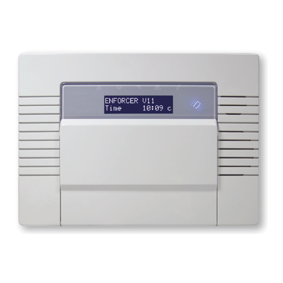
- Page 1 Installation Manual RINS1903-1 EN50131-1:2006+A1:2009 EN50131-3:2009 EN50131-6:2008 Enforcer Time 10:09 c EN50131-5-3:2005+A1:2008 PD6662:2010+IA:2015 Software Version >10 PIEZO WARNING The Enforcer system contains a 100dBA siren, please be aware of this after an activation...
-
Page 2: Table Of Contents
2.1 Technical Specification ......................4 3. Installation Guide ........................5 3.1 Mains and Earth Wiring ......................5 3.2 Inside of the Enforcer: Rear ....................6 3.3 Inside of the Enforcer: Front ....................6 3.4 Connecting / Replacing the Control Panel Battery ..............7 3.5 Important Installation Notes .................... -
Page 3: Introduction
1 . I n t r o d u c t i o n The Enforcer is a wireless alarm system that has been designed to enable easy installation and minimal maintenance. The Enforcer protects the property (domestic or commercial) with a multitude of unique features: •... -
Page 4: Specification And Warranty
Enforcer: Installation Manual 2 . S p e c i f i c a t i o n a n d W a r r a n t y 2.1 Technical Specification Enforcer Mains Inputs European rated voltage 230V AC -15/+10%... -
Page 5: Installation Guide
3 . I n s t a l l a t i o n G u i d e NOTE 1: It is recommended that the Engineer menu is accessed prior to opening a powered Enforcer. NOTE 2: If any new peripheral is installed (i.e. Modem, I/O board, Expander) it is recommended that the Enforcer is powered down (mains and battery). -
Page 6: Inside Of The Enforcer: Rear
3. The transformer is situated in a housing. 4. The rear tamper adjustment screw is used if the tamper from the front of the Enforcer isn't sitting flush to the back plate - this may happen if the Enforcer is installed on an uneven surface. -
Page 7: Connecting / Replacing The Control Panel Battery
Ensure that the Input and Output Board (I/O Board) used to connect wired keypads, readers, inputs and outputs to the Enforcer, and is only connected to circuits operating at SELV voltage. When securing external wires, ensure that means are provided in the installation to prevent the SELV or signal circuits from coming into contact with live parts of the power supply circuit. -
Page 8: Rs232 Connection / Uploading And Downloading Software
3.6 RS232 Connection / Uploading and Downloading Software The Enforcer PC software (InSite) can be downloaded from http://www.pyronix.com/pyronix- downloads.php. To enable the Enforcer to receive upload/download commands, refer to the function ‘SET UP DOWNLOAD’ in the programming manual. Serial Connection (RS232) 1. -
Page 9: Input / Output Board
3.8 Connecting Peripherals to the I/O Board Connecting Keypads (EURO-LCDPZ) Up to 3 additional keypads can be connected to the Enforcer. These will be addressed individually and also addressed in the Engineer function '‘Assign Keypads / Readers’. Addressing at the keypad Each keypad will also need to be addressed individually, press and hold the D key until ‘SECURITY CODE’... - Page 10 Enforcer: Installation Manual Connecting Internal Tag Readers (EUR-107) Up to 3 readers can be connected to the Enforcer. Each keypad or reader need to be addressed as described below. These will also need assigning in the Engineer function '‘Assign Keypads / Readers’.
- Page 11 Enforcer: Installation Manual Wiring a Wired External Sounder To create the bell tamper circuit, a resistor is required across 0V supply and tamper circuit of the bell box. Note that the input must be programmed as ‘tamper’. The resistor value will correspond to the value selected in ‘WIRING CHOICE’.
-
Page 12: Connecting A Wired Input Expander
Enforcer: Installation Manual 3.9 Connecting a Wired Input Expander Up to 4 x Remote Input Expanders can be connected to the Enforcer. NOTE: The above shows the I/O board connected to a EURO-ZEM8+, the connections for a EURO- ZEM8 are done in the same way. NOTE: If using a EURO-ZEM8+PSU, the D2+ MUST NOT be connected. -
Page 13: Connecting An Output Expander
ZEM Address 3 3.11 Connecting an Output Expander 1 x Remote Output Expander can be connected to the Enforcer. Each output expander allows 16 additional outputs. NOTE: The above shows the I/O board connected to a EURO-OEM8R8T. If using a EURO- OEM16R+PSU, the D2+ MUST NOT be connected. -
Page 14: Digi Wi-Fi (Wi-Fi Module)
Password entry. 3.13 Other Module Options The Enforcer has other options of , LAN, GPRS, GSM, VOICE or PSTN modules for communication. In order to communicate with the cloud and with an ARC simultaneously, the Enforcer is also compatible with CSL DigiAir Pyronix modules. These come in three variants of Wi-Fi, LAN and GPRS. Please refer to the ‘Modem and Communication Guide’... - Page 15 Enforcer: Installation Manual Page: 15...
- Page 16 Customer Support line (UK Only): +44(0)845 6434 999 (local rate) or +44(0)1709 535225 Hours: 8:00am - 6:30pm, Monday to Friday Email: customer.support@pyronix.com Website: www.pyronix.com...