Sign In
Upload
Manuals
Brands
TRENDnet Manuals
Switch
TEG-S224S
TRENDnet TEG-S224S Manuals
Manuals and User Guides for TRENDnet TEG-S224S. We have
2
TRENDnet TEG-S224S manuals available for free PDF download: User Manual, Specifications
TRENDNET TEG-S224S User Manual (206 pages)
Stackable NWay Ethernet Switch
Brand:
TRENDNET
| Category:
Switch
| Size: 4.52 MB
Table of Contents
Ce Mark Warning
2
Fcc Warning
2
VCCI Warning
2
Table of Contents
3
About this Guide
12
Conventions
12
Overview of this User's Guide
12
Introduction
15
Fast Ethernet Technology
15
Gigabit Ethernet Technology
16
Switching Technology
17
Features
18
Ports
18
Performance Features
19
Management
20
Unpacking and Setup
21
Unpacking
21
Setup
22
Desktop or Shelf Installation
22
Rack Installation
23
Figure 2-1. Switch Installed on a Desktop or Shelf
23
Figure 2-2A. Attaching the Mounting Brackets to the Switch
23
Power on
24
Figure 2-2B. Installing the Switch in an Equipment Rack
24
Power Failure
25
Identifying External Components
26
Front Panel
26
Figure 3-1. Front Panel View of the Switches
26
Rear Panel
27
Side Panels
28
Figure 3-2. Rear Panel View of the Switches
28
Stack Operation
29
Figure 3-3. Side Panel Views of the Switch
29
Figure 3-4. Switch Stack with One Master and Three Clients
30
Optional Plug-In Modules
31
Figure 3-5. Switch Stack with Example of Possible Connections
31
100BASE-FX (MT-RJ) Module
32
100BASE-FX (SC) Module
32
Figure 3-6. Two-Port, 100BASE-FX (MT-RJ) Module
32
Figure 3-7. One-Port, 100BASE-FX (SC) Module
32
100BASE-TX Module
33
Figure 3-8. Two-Port, 100BASE-TX Module
33
1000BASE-SX Gigabit Module
34
Figure 3-9. One-Port, 1000BASE-SX Gigabit Module
34
1000BASE-LX Gigabit Module
35
Led Indicators
35
Figure 3-10. One-Port, 1000BASE-LX Gigabit Module
35
Figure 3-11. the Switch LED Indicators
36
Connecting the Switch
38
Switch to End Node
38
Switch to Hub or Switch
39
Figure 4-1. Switch Connected to an End Node
39
10BASE-T Device
40
Figure 4-2. Switch Connected to a Normal (Non-Uplink) Port on a Hub or Switch Using a Straight or Crossover Cable
40
100BASE-TX Device
41
Switch Management Concepts
42
Local Console Management
42
Diagnostic (Console) Port (RS-232 DCE)
43
Ip Addresses and Snmp Community Names
43
Traps
44
Mibs
46
Packet Forwarding
47
Aging Time
47
Filtering Database
48
Spanning Tree Algorithm
49
STA Operation Levels
49
On the Bridge Level
50
On the Port Level
50
User-Changeable STA Parameters
51
Illustration of STA
52
Figure 5-1. before Applying the STA Rules
53
Figure 5-2. after Applying the STA Rules
53
Port Trunking
54
Table 5-1. User-Selective STA Parameters
54
Figure 5-3. Port Trunking Example
55
Vlan
56
IEEE 802.1Q Vlans
57
VLAN Segmentation
57
Sharing Resources Across Vlans
58
Figure 5-4. Example of Typical VLAN Configuration
58
Vlans Spanning Multiple Switches
59
Table 5-2. Example of Possible VLAN Assignments
59
Vlans over 802.1Q-Compliant Switches
61
Figure 5-5. Data Transmissions between 802.1Q-Compliant Switches
62
Broadcast Management
63
Broadcast Storms
63
Port-Based Broadcast Packet Filter
64
MAC-Based Broadcast Packet Filter
64
Using the Console Interface
65
Connecting to the Switch
65
Console Usage Conventions
66
First Time Connecting to the Switch
67
Figure 6-1. Initial Screen, First Time Connecting to the Switch
67
User Accounts Management
68
Administrator and Normal User Privileges
69
Save Changes
70
Table 6-1. Administrator and Normal User Privileges
70
Login on the Switch Console by Registered Users
71
Create/Modify User Accounts
71
Figure 6-4. User Accounts Management Menu
72
Figure 6-5. Add/Modify User Accounts Screen
72
View/Delete User Accounts
73
Setting up the Switch
74
System Configuration
74
Figure 6-6. View/Delete User Accounts Screen
74
Configure IP Address
75
Figure 6-7. System Configuration Menu
75
Figure 6-8. IP Address Configuration Screen
76
Configure Console
77
Figure 6-9. Console Options Screen
78
Configure Switch Stack
79
Figure 6-10. Switch Stack Configuration Screen
79
Figure 6-11 Information of Individual Switch Unit Screen
80
Information of Individual Switch Unit
80
Advance Settings
81
Figure 6-12. Configure Advanced Switch Features Screen
81
Configure Port
82
Figure 6-13. Port Configuration Screen
82
Configure Trunk
85
Figure 6-14. Port Trunk Screen
85
Configure Port Mirroring
86
Configure Spanning Tree Protocol
87
Figure 6-15. Port Mirroring Configuration Screen
87
Figure 6-16. Configure Spanning Tree Protocol Menu
88
STP Parameter Settings
88
Figure 6-17. STP Parameter Setting Screen
89
Figure 6-18. STP Custom Settings Screen
92
STP Custom Settings
92
Configure Filtering and Forwarding Table
93
Figure 6-19. Configure Filtering and Forwarding Table Screen
94
Configure Static Forwarding Table Entry
95
Figure 6-20. Static Forwarding Table Configuration Screen
95
Configure MAC Address Filtering
96
Configure Permanent Multicast Filtering
97
Figure 6-21. Custom Filtering Table Screen
97
Configure IGMP
98
Figure 6-22. Static Multicast Filtering Table Configuration Screen
98
Figure 6-23. IGMP Configuration Screen
99
Figure 6-24. IEEE 802.1Q IGMP Configuration Screen
100
Figure 6-25. Add/Remove IGMP Entry Screen
101
Configure Vlans & MAC-Based Broadcast Domains
102
Figure 6-26. IEEE 802.1Q IGMP Configuration Screen
102
Figure 6-27. Vlans & MAC-Based Broadcast Domains Configuration Screen
103
Configure MAC-Based Broadcast Domains
104
Figure 6-28. MAC-Based Broadcast Domains Configuration Menu
105
Figure 6-29. Add/Remove MAC-Based Broadcast Domains Screen
105
Figure 6-30. Add/Remove MAC-Based Broadcast Domain Members Screen
106
Configure IEEE 802.1Q Vlans
107
Figure 6-31. Add/Remove MAC-Based Broadcast Domain Members Screen
107
Figure 6-32. IEEE 802.1Q Vlans Configuration Menu
108
Figure 6-33. Ingress Filtering Check Screen
109
Figure 6-33. Default Port VLAN Assignment Screen
110
Figure 6-34. 802.1Q Static VLAN Settings Screen
111
Figure 6-35. Browse 802.1Q VLAN Entries Screen
112
Update Firmware and Configuration Files
112
Figure 6-36. Update Firmware and Configuration Files Screen
113
Special Note Concerning Firmware Updates
114
System Utilities
114
Figure 6-37. Utilities Menu
115
Figure 6-38. Ping Test Screen
115
Ping Test
115
Figure 6-39. Save Settings to TFTP Server Screen
116
Save Settings to TFTP Server
116
Figure 6-40. Save Switch History to TFTP Server Screen
117
Save Switch History to TFTP Server
117
Clear Address Table
118
Community Strings and Trap Stations
118
Figure 6-41. SNMP Manager Configuration Screen
119
Figure 6-42. Network Monitoring Menu
120
Network Monitoring
120
Switch Monitoring
120
Figure 6-43. Traffic Statistics Menu
121
Port Utilization
121
Traffic Statistics
121
Figure 6-44. Port Utilization Screen
122
Port Traffic Statistics
122
Figure 6-45. Port Traffic Statistics Screen
123
Figure 6-46. Port Packet Error Statistics Table
124
Port Packet Error Statistics
124
Figure 6-47. Packet Analysis Statistics Table
126
Port Packet Analysis Statistics
126
Browse Address Table
127
Figure 6-48. Browse Address Table
128
Switch History
128
Browse IGMP Status
129
Figure 6-49. Switch History Screen
129
Figure 6-50. IP Multicast Information Screen
130
Resetting the Switch
131
Restart System
131
Factory Reset
132
Figure 6-51. Restart System Screen
132
Logout
133
Figure 6-52. Factory Reset NV-RAM to Default Value Screen
133
Web-Based Network Management
134
Introduction
134
Getting Started
135
Management
135
Configuration
136
Figure 7-1. Configure IP Address Window
137
IP Address
137
Figure 7-2. Configure Switch Stack Window
138
Switch
138
Advanced
140
Figure 7-3. Configure Switch Stack - Advanced Window
140
Figure 7-4. Information of Individual Switch Unit Window
141
Switch Unit
141
Figure 7-5. Configure Port Window
142
Port
142
Figure 7-6. Port Trunk Window
144
Port Trunk
144
Figure 7-7. Port Mirroring Window
145
Port Mirroring
145
Spanning Tree Protocol
146
Figure 7-8. STP Parameter Setting Window
147
STP Parameters Setting
147
Figure 7-9. Spanning Tree Custom Setting Window
148
STP Custom Setting
148
Forwarding and Filtering
149
Figure 7-10. Configure Forwarding Table and Filtering Table Window
150
Figure 7-11. Static Forwarding Table Window
151
Static Forwarding Table
151
Figure 7-12. Static Forwarding Table
152
Figure 7-13. Static MAC Address Filtering Window
153
MAC Address Filtering Table
153
Figure 7-14. Static MAC Address Filtering
154
Figure 7-15. Static Permanent Multicast Filtering Window
155
Permanent Multicast Filtering
155
Figure 7-16. Static Permanent Multicast Filtering--Edit Window
156
Igmp
156
Figure 7-17. Configure IGMP Window
157
IGMP Settings
157
802.1Q Igmp
158
Figure 7-18. Add/Remove IGMP Table Window
158
Figure 7-19. Add/Remove IGMP Table-Edit Window
159
Vlans & MAC-Based Broadcast Domains
159
Figure 7-20. Configure VLAN Window
160
MAC-Based Broadcast Domains
160
Figure 7-21. Add/Remove MAC-Based Broadcast Domains Window
161
Figure 7-22. Add/Remove MAC-Based Broadcast Domains --- Edit Window
162
Figure 7-23. Add/Remove MAC-Based Broadcast Domain Member Window
163
Figure 7-25. Default Port VLAN ID Window
165
IEEE 802.1Q Vlans
165
Figure 7-26. Port Ingress Filtering Check Window
166
Figure 7-27. 802.1Q Static VLAN Entry Window (Number One)
167
Management
168
Figure 7-28. 802.1Q Static VLAN Entry Window (Number Two)
168
Community Strings and Trap Stations
169
Figure 7-29. Community Strings and Trap Stations Window
169
Figure 7-30. User Accounts Window
170
User Account
170
Figure 7-31. User Account-Edit Window
171
Console
172
Figure 7-32. Configure Console Window
172
Monitoring
173
Figure 7-33. Switch Statistics Window
173
Switch Overview
173
Figure 7-34. Port Utilization Window
174
Port Utilization
174
Figure 7-35. Port Traffic Statistics Window
175
Port Traffic Statistics
175
Figure 7-36. Port Error Packet Statistics Window
177
Port Error Packet Statistics
177
Figure 7-37. Port Packet Analysis Window
179
Port Packet Analysis Statistics
179
Browse Address Table
181
Figure 7-38. Browse Address Table Window
181
Browse IGMP Status
182
Figure 7-39. Browse IGMP Status Window
182
Switch History
183
Maintenance
183
Figure 7-40. Switch History Window
183
Figure 7-41. Firmware and Configuration Update Window
184
Firmware and Configuration Update
184
Figure 7-42. Save Settings to TFTP Server Window
185
Save Settings to TFTP Server
185
Figure 7-43. Save Switch History to TFTP Server Window
186
Save Switch History to TFTP Server
186
Figure 7-44. Save Changes Window
187
Save Changes
187
Factory Reset
188
Figure 7-45. Factory Reset to Default Value Window
188
Figure 7-46. Restart System Window
189
Restart System
189
Technical Specifications
190
Physical and Environmental
191
Pin Specification
194
Figure B-1. the Standard RJ-45 Receptacle/Connector
194
Figure B-2. Straight Cable for Switch (Uplink MDI-II Port) to Switch/Hub or Other Devices Connection
195
Figure B-3. Crossover Cable for Switch (MDI-X Port) to Switch/Hub or Other Network Devices (MDI-X Port) Connection
196
Sample Configuration File
197
Commands
197
Notes about the Configuration File
198
Runtime Software Default Settings
200
Index
202
Advertisement
TRENDnet TEG-S224S Specifications (2 pages)
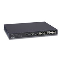
24-port 10/100Mbps Management Stackable Fast Ethernet Slave Switch
Brand:
TRENDnet
| Category:
Switch
| Size: 0.21 MB
Advertisement
Related Products
TRENDnet TEG-S224 - DATA SHEETS
TRENDnet TEG-S224M
TRENDnet TEG-S224TX
TRENDnet TEG-S224TXA - 26PORT Gigabit Copper Switch 24-10/100 2-10/100/1000
TRENDnet TEG-S224 Series
TRENDnet TEG-S2400I - DATA SHEETS
TRENDnet TEG-S24R - DATA SHEETS
TRENDnet TEG-S24Dg
TRENDnet TEG-S28TX
TRENDNET GREENnet TEG-S24g
TRENDnet Categories
Switch
Adapter
Wireless Router
Network Router
Security Camera
More TRENDnet Manuals
Login
Sign In
OR
Sign in with Facebook
Sign in with Google
Upload manual
Upload from disk
Upload from URL