Table of Contents
Advertisement
Quick Links
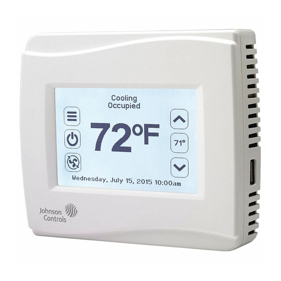
TEC3000 Series Wireless Single- or Two-Stage Economizer
Thermostat Controllers
Installation Instructions
TEC3030-xx-xxx, TEC3031-xx-xxx
Applications
The TEC3000 Series Wireless Single- or Two-Stage Economizer Thermostat Controllers are wireless networked
devices that provide control of the following:
•
unitary rooftop units (RTUs)
•
unitary RTUs with economizers
•
unitary RTUs with heat pumps
•
unitary RTUs with economizers and heat pumps
The networked models are compatible with the WNC1800/ZFR182x Pro Series Wireless Field Bus System that
enables remote monitoring and programming for efficient space temperature control. All models include a USB port
configuration that reduces installation time by allowing simple backup and restore features from a USB drive, which
enables rapid cloning of configuration between like units.
Some models have occupancy sensing capability built into the device. These thermostat controllers maximize up to
30% energy savings in high-energy usage commercial buildings, such as schools and hotels, during occupied
times by using additional standby setpoints.
All models feature an intuitive UI with backlit display that makes setup and operation quick and easy. Only the
single-speed fan configuration is supported for fan coil equipment types.
TEC3000 Series Wireless Single- or Two-Stage Economizer Thermostat
Refer to the
QuickLIT website
Controllers Installation Instructions
1
*241078913D*
24-10789-13, Rev. D
(barcode for factory use only)
Part No. 24-10789-13, Rev. D
for the most up-to-date version of this document.
Issued July 2018
Advertisement
Table of Contents

Related Manuals for Johnson Controls TEC3010


Summary of Contents for Johnson Controls TEC3010
- Page 1 *241078913D* 24-10789-13, Rev. D (barcode for factory use only) TEC3000 Series Wireless Single- or Two-Stage Economizer Thermostat Controllers Installation Instructions Part No. 24-10789-13, Rev. D Issued July 2018 TEC3030-xx-xxx, TEC3031-xx-xxx Refer to the QuickLIT website for the most up-to-date version of this document. Applications The TEC3000 Series Wireless Single- or Two-Stage Economizer Thermostat Controllers are wireless networked devices that provide control of the following:...
-
Page 2: North American Emissions Compliance
IMPORTANT: The TEC3000 Series Thermostat Controller is intended to provide an input to equipment under normal operating conditions. Where failure or malfunction of the thermostat controller could lead to personal injury or property damage to the controlled equipment or other property, additional precautions must be designed into the control system. -
Page 3: Location Considerations
Location Considerations Locate the TEC3000 Series Wireless Thermostat Controller: • on a partitioning wall, approximately 5 ft (1.5 m) above the floor in a location of average temperature, allowing for vertical air circulation to the TEC • away from direct sunlight, radiant heat, outside walls, outside doors, air discharge grills, stairwells, and from behind doors •... -
Page 4: Installing The Thermostat Controller
Installing the Thermostat Controller 1. Use a 1/16 in. (1.5 mm) Allen wrench or Johnson Controls® T-4000-119 Allen-Head Adjustment Tool (order separately) to remove the security screw if it is installed on the top of the thermostat controller cover as illustrated in Figure 2. - Page 5 Figure 2: Removing the Security Screw from the Thermostat Controller Cover (Shown with Occupancy Sensor) (Left) and Removing the Thermostat Controller Cover (Right) 3. Align the thermostat controller mounting base on the wall with the security screw on the top and use the base as a template to mark the two mounting hole locations.
- Page 6 Wiring When an existing thermostat controller is replaced, remove and label the wires to identify the terminal functions. Risk of Electric Shock. Disconnect the power supply before making electrical connections to avoid electric shock. Risque de décharge électrique. Débrancher l'alimentation avant de réaliser tout raccordement électrique afin d'éviter tout risque de décharge électrique.
- Page 7 TEC3020 TEC3031 5. Use a 1/16 in. (1.5 mm) Allen wrench or Johnson Controls T-4000-119 Allen-Head Adjustment Tool (order separately) to reinstall the security screw on the top of the thermostat controller cover. See Figure 2 for security screw placement.
- Page 8 Table 3: Terminal Identification (See Figure 6 for Wiring Diagram) Terminal Label Function TEC3030, TEC3031 24 V 24 VAC hot from the sensor Cooling stage 1 Cooling stage 2 Economizer Auxiliary output Auxiliary output W1 OB Heating 1 (RTU mode)/Reversing valve (O/B) (Heat Pump mode) Power for W1 and W2 W2 SUP Heating 2 (RTU mode)/Supplemental heat (Heat Pump mode)
- Page 9 Note: Only one transformer is required for each TEC. Figure 5: Staged Wiring Diagram - Rooftop Unit (See Table 3 for Terminal Identification) Outdoor Air Temp Heat 1 W2 SUP W1 OB Cool 2 Cool 1 24 V Common R SEN Supply/Aux Thermistor Thermistor...
- Page 10 Note: Only one transformer is required for each TEC. Figure 6: Staged Wiring Diagram - Heat Pump (See Table 3 for Terminal Identification) Outdoor Air Temp W2 SUP W1 OB Compressor Compressor 24 V Common R SEN Supply/Aux Thermistor Thermistor 24 V Economizer Common...
-
Page 11: Setup And Adjustments
Figure 7: AUX Contact Wiring 19 to 30 VAC AUX Contact Load Figure 8: Binary Input Wiring Dry Contact Dry Contact Setup and Adjustments IMPORTANT: Table 10 provides a full list of TEC3000 menu settings. In the upcoming sections, step-by-step instructions are included on how to access and adjust the more commonly used menus. -
Page 12: Customizing The Home Screen
Customizing the Home Screen Customizing the Home screen settings include: • Brightness • Units • Time Zone • Date • Enable Backlight • Time • Time Format • Date Format You can also show or hide these items on the Home screen: •... - Page 13 Table 4: Touchscreen Icons (Part 2 of 3) Icon Icon Name Description Indicates the signal strength of the TEC’s connection to the wireless network. Blank or three empty bars indicates that there is no connection to the PAN and the supervisory controller.
-
Page 14: User Lockout
Table 4: Touchscreen Icons (Part 3 of 3) Icon Icon Name Description Returns the display to the main home screen. Home Returns to the previous screen. Back Saves the current configuration and parameter settings. Save Deletes the scheduled event. Delete Clears the password entry on the keypad screen. - Page 15 3. Press the Menu icon. 4. Scroll down the menu and press Update. 5. Press Load Firmware. 6. Select the correct firmware version. The correct file name has the .pkg extension. 7. Press Confirm if you have the correct firmware version. The firmware is loaded from the USB drive.
-
Page 16: Configuring The Thermostat Controller
3. Press Network Setup. 4. Press FC Comm Mode and the Wireless Field Bus appears. This setting cannot be changed. 5. Press to return to the previous screen. 6. Press BACnet Instance ID. 7. Enter the unique BACnet® instance ID using the keypad. This value should be different to the other controllers on the site. - Page 17 When in heat pump mode, the TEC controls up to two stages of compressors (Y1, Y2) for both heating and cooling. O/B is controlled through the W1/OB output, and one stage of supplemental heat is controlled through the W2/SUP output. To configure heat pump mode: 1.
-
Page 18: Setting The Control Mode
11. Press to save and to return to the previous screen. The TEC supports the following three methods of determining economizer availability: Dry Bulb, Single Enthalpy, and Dual Enthalpy, in increasing order of accuracy. To run an economizer, outdoor air temperature (OAT) is required to run in Dry Bulb mode. -
Page 19: Configuring The Zone Space Or Equipment Size
The Fan Override icon on the home screen is dependent on the fan type. The following options are provided for single-speed fans: • On—Overrides the fan to be continuously on • Auto—Follows the behavior set as Fan Mode • Quiet—Follows the behavior set as Auto Mode. The Quiet option has no effect on the RTU/heat pump equipment as only a single-speed fan is supported. -
Page 20: Configuring Occupancy
The occupant has access to an up/down adjustment from the home screen. This adjustment applies a fixed offset (+/-) to the currently active setpoint, and this offset holds until the occupancy state of the controller changes. If the user taps the setpoint on the home screen, the icon inverts and displays white text on a black icon. The offset is held throughout all occupancy periods. -
Page 21: Selecting Schedule Source
Occupancy is determined using a top-down decision matrix as shown in Table 7. Enumerations may not match the TEC3000 Series Wireless On/Off or Floating Fan Coil and Individual Zone Thermostat Controllers with Dehumidification Capability Installation Instructions (Part No. 24-10787-14), TEC3000 Series Wireless Proportional Fan Coil and Individual Zone Thermostat Controllers with Dehumidification Capability Installation Instructions (Part No. -
Page 22: Setting The Local Schedule
2. Press Schedule. 3. Press Schedule Options. 4. Press Schedule Source and select Schedule (Local) or External (BAS). 5. Press to save and to return to the previous screen. This option is also exposed to the BAS through the point OCC-CONFIG. If BAS is configured as the occupancy source, map the point NET-OCC in and write to that point in order to control the schedule remotely. - Page 23 Figure 11: Setting the Room Occupancy (Left) and Setting the Occupancy Mode (Right) 8. Set the time to the time at which the event should occur and press the Save icon. Figure 12: Setting the Event Time (Left) and Viewing the Event Time (Right) 9.
-
Page 24: Overriding The Occupancy Mode
Overriding the Occupancy Mode The TEC supports a manual override of all other schedule sources (for example, Schedule, Occupancy BI, and temporary occupancy). This override can be set as follows: 1. Press the Menu icon. 2. Press Schedule. 3. Press Schedule Options. 4. -
Page 25: Configurable Binary Inputs
Additionally, the PID features Johnson Controls proprietary PRAC+ automatic tuning, which continuously tunes the controller parameters to automatically optimize the control performance to match the equipment and zone. For units configured with two stages of heating or cooling, PRAC+ is enabled and immediately begins to tune. To reset tuning at any time to the factory defaults: 1. -
Page 26: Aux Control
• Service—Input from the equipment to display a service warning on the thermostat • Dirty Filter—Input from the equipment to display a dirty filter fault on the thermostat • Motion NC—External motion sensor with a closed contact output when no motion is detected •... -
Page 27: Commissioning Mode
• Off—Output is turned off (relay open), used by a BAS to directly control the AUX output To set the Aux Mode: 1. Press the Menu icon. 2. Press Control Setup. 3. Press General. 4. Press Aux Mode and set accordingly. 5. - Page 28 • Supply Air Temperature Diagnostics—The TEC3000 supports diagnostics when you have a Supply Air Temperature installed. The TEC3000 monitors the supply air. If you call for cooling or heating and the temperature does not fall or rise by at least the supply air temperature alarm offset value within the supply air temperature alarm delay, an alarm is generated.
-
Page 29: Menus And Submenus
Menus and Submenus In the following table, the * indicates that the menus depend on your configuration. Table 10: Menus and Submenus (Part 1 of 9) Level 1 Level 2 Level 3 Available Values (LCD Screen Name) (Default Values) Setpoints Occ Cooling Setpoint 72°F (22°C) 55 to 85°F (13 to 30°C) - Page 30 Table 10: Menus and Submenus (Part 2 of 9) Level 1 Level 2 Level 3 Available Values (LCD Screen Name) (Default Values) Schedule Schedule Options Optimal Start Enable Yes or No Temp Occ Duration 120 minutes 0 to 300 minutes Motion Sensor Timeout 15 minutes 15 to 240 minutes...
- Page 31 Table 10: Menus and Submenus (Part 3 of 9) Level 1 Level 2 Level 3 Available Values (LCD Screen Name) (Default Values) Control Setup Aux Mode Not Used Not Used, Occupied NO, Occupied NC, (Cont) Occupied Fan NO, Occupied Fan NC, On, Off Load Shed Rate Limit 0.066°F...
- Page 32 Table 10: Menus and Submenus (Part 4 of 9) Level 1 Level 2 Level 3 Available Values (LCD Screen Name) (Default Values) Control Setup Deadband* 0.7 to 1.5°F 1.0°F (-17.22 °C) (Cont) *Functionally, this is the PID deadband when the Temp Control Setup is equal to the Deadband Override or Manual PID Tuning.
- Page 33 Table 10: Menus and Submenus (Part 5 of 9) Level 1 Level 2 Level 3 Available Values (LCD Screen Name) (Default Values) Control Setup Econ Prop Band* 160°F 5 to 10°F (-15 to -1.11°C) (Cont) *Values only appear when Auto Economizer Tuning is Disabled.
- Page 34 Table 10: Menus and Submenus (Part 6 of 9) Level 1 Level 2 Level 3 Available Values (LCD Screen Name) (Default Values) Equipment Setup General Number of Compressor One-Stage Not Used, One-Stage, Two-Stage Lead/Lag Equalize Runtime Yes or No Number of Heating Stages* Two-Stage Not Used, One-Stage, Two-Stage * Heat pump unit,...
- Page 35 Table 10: Menus and Submenus (Part 7 of 9) Level 1 Level 2 Level 3 Available Values (LCD Screen Name) (Default Values) — Trend EFF-ZNT -50 to 250°F (-45.56 to 121.11°C) — EFF-SETPOINT 45 to 100°F (7.22 to 37.78°C) — EFF-ZNH 0 to 100%RH —...
- Page 36 Table 10: Menus and Submenus (Part 8 of 9) Level 1 Level 2 Level 3 Available Values (LCD Screen Name) (Default Values) System Status Occupancy Source Occupancy Sensor Occupancy BI Temp Occ BI Temp Occ Occ Override Local Schedule BAS Schedule Occupancy Sensor Unit Status Idle...
- Page 37 Table 10: Menus and Submenus (Part 9 of 9) Level 1 Level 2 Level 3 Available Values (LCD Screen Name) (Default Values) — Commissioning Supply Air Temperature Display Current Temperature Heat Command 0 to 100% Cool Command 0 to 100% Supply Fan Yes or No Yes or No...
- Page 38 Table 11: TE-6300 Series Temperature Sensors (Order Separately) (Part 1 of 2) Mounting Style Probe Length Product Code Number Nickel 8 in. (203 mm) TE-6311A-1 Adjustable (1k ohm) Averaging 8 ft (2.4 m) TE-6315M-1 TE-6315V-2 17 ft (5.2 m) TE-6316M-1 TE-6316V-2 Duct 4 in.
-
Page 39: Troubleshooting
Table 11: TE-6300 Series Temperature Sensors (Order Separately) (Part 2 of 2) Mounting Style Probe Length Product Code Number Thermistor Adjustable 8 in. (203 mm) TE-6341A-1 (2.2k ohm) Duct 8 in. (203 mm) TE-6341P-1 Flange 4 in. (102 mm) TE-634GV-2 8 in. - Page 40 Internal Sensor Fail An internal sensor has failed on the Order replacement units and return the affected TEC. devices to Johnson Controls under the RMA program. OA Lockouts Disabled The Local Outdoor Air Temperature 1. If the source of outdoor air temperature was a...
- Page 41 Controller Fault The controller has detected an internal Order replacement units and return the affected fault that it cannot recover. devices to Johnson Controls under the RMA program. An unknown error has prevented the Order replacement units and return the affected controller from turning on.
- Page 42 Table 12: Fault List (Part 4 of 4) Faults Probable Causes Solutions Zone Temperature Too Cold The Zone Temperature has decreased Verify that the TEC and the RTU heating are below the configured Zone Temp Low enabled and functioning. Limit. Zone Temperature Too Hot The Zone Temperature has increased Verify that the TEC and the RTU cooling are...
- Page 43 A hardware failure is causing the two Order replacement units and return the boards to incorrectly identify affected devices to Johnson Controls themselves. under the RMA program. The controller displays Controller An internal fault was detected and the Order replacement units and return the Fault.
-
Page 44: Repair Information
Bulletin (LIT-12012356). Repair Information If the TEC3000 Series Thermostat Controller fails to operate within its specifications, replace the unit. For a replacement thermostat controller, contact the nearest Johnson Controls representative. TEC3000 Series Wireless Single- or Two-Stage Economizer Thermostat Controllers Installation Instructions... -
Page 45: Technical Specifications
The performance specifications are nominal and conform to acceptable industry standards. For application at conditions beyond these specifications, consult the local Johnson Controls office. Johnson Controls shall not be liable for damages resulting from misapplication or misuse of its products. - Page 46 507 E. Michigan Street, Milwaukee, WI 53202 Metasys® and Johnson Controls® are registered trademarks of Johnson Controls. All other marks herein are the marks of their respective owners. © 2018 Johnson Controls. TEC3000 Series Wireless Single- or Two-Stage Economizer Thermostat Controllers Installation Instructions Published in U.S.A.