Table of Contents
Advertisement
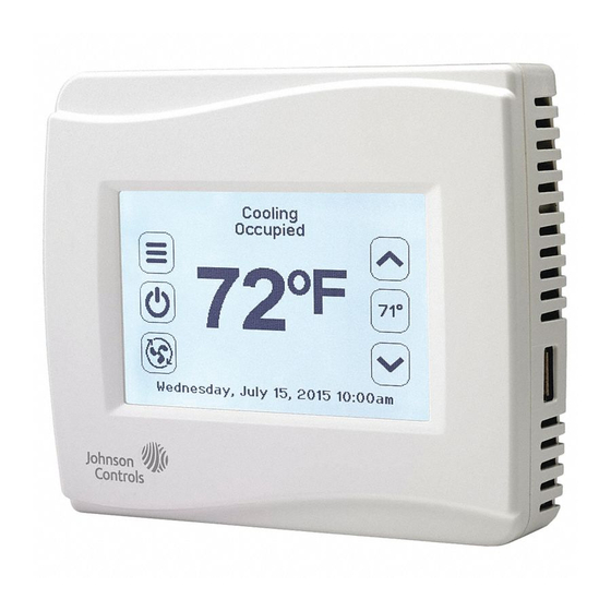
TEC3000 Series Wireless Proportional Fan Coil and
Individual Zone Thermostat Controllers with
Dehumidification Capability
Installation Instructions
TEC3020-xx-xxx, TEC3021-xx-xxx, TEC3022-xx-xxx, TEC3023-xx-xxx
Applications
The TEC3000 Series Wireless Proportional Fan Coil and Individual Zone Thermostat Controllers are wireless
networked devices that provide control of the following:
•
local hydronic reheat valves
•
pressure-dependent variable air volume (VAV) equipment with or without local reheat
•
two- or four-pipe fan coils
•
cabinet unit heaters
•
other individual zone equipment using a proportional 0 to 10 VDC control input
The networked models are compatible with the WNC1800/ZFR182x Pro Series Wireless Field Bus System that
enables remote monitoring and programming for efficient space temperature control. All models include a USB port
configuration that reduces installation time by allowing simple backup and restore features from a USB drive, which
enables rapid cloning of configuration between like units.
Some models have occupancy sensing capability built into the device. These thermostat controllers maximize up to
30% energy savings in high-energy usage commercial buildings, such as schools and hotels, during occupied
times by using additional standby setpoints.
All models feature an intuitive UI with backlit display that makes setup and operation quick and easy. Multiple fan
configurations are supported for fan coil equipment types:
•
single-speed
•
multi-speed (two or three discrete speeds)
•
variable-speed/EC motors (0 to 10 VDC control)
Some models support dehumidification on two-pipe fan coil units with reheat, and four-pipe fan coil units with or
without reheat. When no heating is required, the thermostat controller monitors space humidity and activates
dehumidification control as necessary. Heat and reheat is used as required to maintain the space temperature. For
optimal dehumidification performance, use a fan coil unit that has a multi-speed or variable-speed fan (VSF).
TEC3000 Series Wireless Proportional Fan Coil and Individual Zone
Refer to the
Thermostat Controllers with Dehumidification Capability
Installation Instructions
*241078819D*
24-10788-19, Rev. D
(barcode for factory use only)
QuickLIT website
for the most up-to-date version of this document.
1
Part No. 24-10788-19, Rev. D
Issued July 2018
Advertisement
Table of Contents

Related Manuals for Johnson Controls TEC3010


Summary of Contents for Johnson Controls TEC3010
- Page 1 *241078819D* 24-10788-19, Rev. D (barcode for factory use only) TEC3000 Series Wireless Proportional Fan Coil and Individual Zone Thermostat Controllers with Dehumidification Capability Part No. 24-10788-19, Rev. D Issued July 2018 Installation Instructions TEC3020-xx-xxx, TEC3021-xx-xxx, TEC3022-xx-xxx, TEC3023-xx-xxx Refer to the QuickLIT website for the most up-to-date version of this document.
-
Page 2: North American Emissions Compliance
IMPORTANT: The TEC3000 Series Thermostat Controller is intended to provide an input to equipment under normal operating conditions. Where failure or malfunction of the thermostat controller could lead to personal injury or property damage to the controlled equipment or other property, additional precautions must be designed into the control system. -
Page 3: Location Considerations
Location Considerations Locate the TEC3000 Series Wireless Thermostat Controller: • on a partitioning wall, approximately 5 ft (1.5 m) above the floor in a location of average temperature, allowing for vertical air circulation to the TEC • away from direct sunlight, radiant heat, outside walls, outside doors, air discharge grills, stairwells, and from behind doors •... -
Page 4: Installing The Thermostat Controller
IMPORTANT: Only connect memory devices to the USB port. Do not use it for charging external devices. Installing the Thermostat Controller 1. Use a 1/16 in. (1.5 mm) Allen wrench or Johnson Controls® T-4000-119 Allen-Head Adjustment Tool (order separately) to remove the security screw if it is installed on the top of the thermostat controller cover. - Page 5 Figure 2: Removing the Security Screw from the Thermostat Controller Cover (Shown without Occupancy Sensor) (Left) and Removing the Thermostat Controller Cover (Right) 3. Align the thermostat controller mounting base on the wall with the security screw on the top and use the base as a template to mark the two mounting hole locations.
- Page 6 Wiring When an existing thermostat controller is replaced, remove and label the wires to identify the terminal functions. Risk of Electric Shock. Disconnect the power supply before making electrical connections to avoid electric shock. Risque de décharge électrique. Débrancher l'alimentation avant de réaliser tout raccordement électrique afin d'éviter tout risque de décharge électrique.
- Page 7 TEC3020 TEC3031 5. Use a 1/16 in. (1.5 mm) Allen wrench or Johnson Controls T-4000-119 Allen-Head Adjustment Tool (order separately) to reinstall the security screw on the top of the thermostat controller cover. See Figure 2 for security screw placement.
- Page 8 Table 3: Terminal Identification (See Figure 5 for Wiring Diagram) Terminal Label Function TEC3020, TEC3021, TEC3022, TEC3023, Proportional FC/VAV 24 V 24 VAC hot from transformer No connect FAN H Fan high FAN M Fan medium FAN L Fan low and fan on Auxiliary binary output Auxiliary power 24 VAC common from transformer...
- Page 9 Note: Only one transformer is required for each TEC. Figure 5: Proportional Wiring Diagram (See Table 3 for Terminal Identification) R SEN SupplyTemp SupplyTemp Thermistor Switch Zone Temp Thermistor 24 V EC Motor Common TEC3000 Series Wireless Proportional Fan Coil and Individual Zone Thermostat Controllers with Dehumidification Capability Installation Instructions...
- Page 10 Note: For VAV and 2-pipe systems, connect the valve to the heating output. Figure 6: Proportional 0 to 10 VDC Control (Pressure-Dependent VAV) Proportional 0 to 10 Actuator Room Temperature Control Thermostat (Minimum and Maximum Position Adjusted on Actuator) Figure 7: Proportional 0 to 10 VDC Control (Pressure-Dependent VAV with Changeover Sensor/Switch) Changeover...
- Page 11 Note: For VAV and 2-pipe systems, connect the valve to the heating output. Figure 9: Floating Control Two-Pipe Heating and Cooling Hydronic Valve Control Fan Coil Application 0 to 10 Room Temperature Control Thermostat Figure 10: Floating Control Two-Pipe Heating and Cooling Hydronic Valve Control with Changeover Fan Coil Application Optional Water Supply Sensor...
-
Page 12: Setup And Adjustments
Figure 12: AUX Contact Wiring 19 to 30 VAC AUX Contact Load Figure 13: Binary Input Wiring Dry Contact Dry Contact Setup and Adjustments IMPORTANT: Table 10 provides a full list of TEC3000 menu settings. In the upcoming sections, step-by-step instructions are included on how to access and adjust the more commonly used menus. -
Page 13: Customizing The Home Screen
Customizing the Home Screen Customizing the Home screen settings include: • Brightness • Units • Time Zone • Date • Enable Backlight • Time • Time Format • Date Format You can also show or hide these items on the Home screen: •... - Page 14 Table 4: Touchscreen Icons (Part 2 of 4) Icon Icon Name Description Indicates the signal strength of the TEC’s connection to the wireless network. Blank or three empty bars indicates that there is no connection to the PAN and the supervisory controller.
- Page 15 Table 4: Touchscreen Icons (Part 3 of 4) Icon Icon Name Description Adjusts the fan override between On, Auto, and Quiet for variable-speed fans. Fan Overrides Variable-speed Fans Auto Quiet Fan Overrides Adjusts the fan override between Low, Medium, High, Auto, and Quiet for multi-speed fans.
-
Page 16: User Lockout
Table 4: Touchscreen Icons (Part 4 of 4) Icon Icon Name Description Indicates that an event or schedule is programmed for a specific day of the week. Checkmark Indicates that an error has occurred. Exclamation Point User Lockout You can select from three different levels of access at the local display to manage functionality through the supervisory controller. - Page 17 4. Scroll down the menu and press Update. 5. Press Backup. A message appears, stating that the file is saved locally and on a USB drive. 6. Press Confirm to save locally and on USB. The setting files are named based on the TEC3000 model name, date, and time stamp (for example, TEC3021-00_2015-10-08T1), They are saved locally and on the USB drive’s root directory.
-
Page 18: Configuring The Thermostat Controller
13. Press to return to the previous screen. 14. Press PAN ID. 15. Enter the PAN ID using the keypad. This value needs to be the same as set in the associated ZFR Pro Coordinator Radio. Once the PAN is set, the TEC attempts to connect to the wireless network. Provided that other devices on the PAN are in radio range, the connection should occur within one minute. -
Page 19: Configuring The Supply Fan - Fan Coil Only
Note: Selecting VAV reboots the controller in order to apply the change. Configuring the Supply Fan - Fan Coil Only On fan coil units (2-pipe or 4-pipe), three different types of supply fans are supported. These are single-speed fan, multi-speed fan (up to three discrete speeds), and VSF using a 0 to 10V control signal and an optional binary on/off command. -
Page 20: Setting The Control Mode
7. Press to save and to return to the previous screen. 8. Press Minimum Command and adjust accordingly. 9. Press to save and to return to the previous screen. Setting the Control Mode The Control Mode informs the controller to either run in Cooling only mode, Heating only mode, or Automatic mode based on the temperature in the zone relative to the heating and cooling setpoints. -
Page 21: Configuring The Zone Space Or Equipment Size
• High—Fan is continuously on high • Auto—Follows the behavior set as Fan Mode • Quiet—Follows the behavior set as Fan Mode, but prevents the fan from ever going above minimum speed To set the Fan Mode: 1. Press the Menu icon. 2. -
Page 22: Dehumidification Control - Fan Coil Only
7. Press to save and to return to the previous screen. Additionally, the thermostat controller supports manual changeover. To configure manual changeover: 1. Press the Menu icon. 2. Press Equipment Setup. 3. Press Changeover. 4. Press Changeover Mode and select Heating or Cooling. 5. -
Page 23: Temperature Setpoints
4. Press to save and to return to the previous screen. This point is also exposed to the BAS through the point DEHUM-SP. Temperature Setpoints The thermostat controller provides a flexible setpoint configuration to give power to the building owner while being easy to use by the occupant. -
Page 24: Configuring Occupancy
Table 6: Setpoint Operation Mode of Setpoint Details Operation Occ Setpoint Select = In this mode, the TEC has one setpoint, Common Setpoint, for heating and cooling. There is Setpoint Offset and also a common Setpoint Offset (warmer/cooler adjust) that is only applied to Common Heat Cool Setpoint Mode = Setpoint. -
Page 25: Selecting Schedule Source
Enumerations may not match the TEC3000 Series Wireless On/Off or Floating Fan Coil and Individual Zone Thermostat Controllers with Dehumidification Capability Installation Instructions (Part No. 24-10787-14), TEC3000 Series Wireless Proportional Fan Coil and Individual Zone Thermostat Controllers with Dehumidification Capability Installation Instructions (Part No. -
Page 26: Setting The Local Schedule
3. Press Schedule Options. 4. Press Schedule Source and select Schedule (Local) or External (BAS). 5. Press to save and to return to the previous screen. This option is also exposed to the BAS through the point OCC-CONFIG. If BAS is configured as the occupancy source, map the point NET-OCC in and write to that point in order to control the schedule remotely. - Page 27 Figure 16: Setting the Room Occupancy (Left) and Setting the Occupancy Mode (Right) 8. Set the time to the time at which the event should occur and press the Save icon. Figure 17: Setting the Event Time (Left) and Viewing the Event Time (Right) 9.
-
Page 28: Overriding The Occupancy Mode
Overriding the Occupancy Mode The TEC supports a manual override of all other schedule sources (for example, Schedule, Occupancy BI, and temporary occupancy). To set the override: 1. Press the Menu icon. 2. Press Schedule 3. Press Schedule Options. 4. Press Manual Occupancy Mode and select Occupied, Unoccupied, or No Override. 5. -
Page 29: Pid/Prac+ Automatic Control Tuning
Additionally, the PID features Johnson Controls proprietary PRAC+ automatic tuning, which continuously tunes the controller parameters to automatically optimize the control performance to match the equipment and zone. By default, PRAC+ is enabled and immediately begins to tune. -
Page 30: Aux Control
• Service—Input from the equipment to display a service warning on the thermostat • Dirty Filter—Input from the equipment to display a dirty filter fault on the thermostat • Motion NC—External motion sensor with a closed contact output when no motion is detected •... -
Page 31: Commissioning Mode
• Off—Output is turned off (relay open), used by a BAS to directly control the AUX output To set the Aux Mode: 1. Press the Menu icon. 2. Press Control Setup. 3. Press General. 4. Press Aux Mode and set accordingly. 5. - Page 32 • Supply Air Temperature Diagnostics—The TEC3000 supports diagnostics when you have a Supply Air Temperature installed. The TEC3000 monitors the supply air. If you call for cooling or heating and the temperature does not fall or rise by at least the supply air temperature alarm offset value within the supply air temperature alarm delay, an alarm is generated.
-
Page 33: Menus And Submenus
Menus and Submenus In the following table, the * indicates that the menus depend on your configuration. Table 10: Menus and Submenus (Part 1 of 8) Level 1 Level 2 Level 3 Available Values (LCD Screen Name) (Default Values) Setpoints Occ Cooling Setpoint 72°F (22°C) 55 to 85°F (13 to 30°C) - Page 34 Table 10: Menus and Submenus (Part 2 of 8) Level 1 Level 2 Level 3 Available Values (LCD Screen Name) (Default Values) Schedule Schedule Options Optimal Start Enable Yes or No Temp Occ Duration 120 minutes 0 to 300 minutes Motion Sensor Timeout 15 minutes 15 to 240 minutes...
- Page 35 Table 10: Menus and Submenus (Part 3 of 8) Level 1 Level 2 Level 3 Available Values (LCD Screen Name) (Default Values) Control Setup Aux Mode Not Used Not Used, Occupied NO, Occupied NC, (Cont) Occupied Fan NO, Occupied Fan NC, On, Load Shed Rate Limit 0.066°F 0 to 1°F (0 to 0.5°C)
- Page 36 Table 10: Menus and Submenus (Part 4 of 8) Level 1 Level 2 Level 3 Available Values (LCD Screen Name) (Default Values) Control Setup Deadband* 0.7 to 1.5°F 1.0°F (-17.22 °C) (Cont) *Functionally, this is the PID deadband when the Temp Control Setup is equal to the Deadband Override or Manual PID Tuning.
- Page 37 Table 10: Menus and Submenus (Part 5 of 8) Level 1 Level 2 Level 3 Available Values (LCD Screen Name) (Default Values) — Network Setup FC Comm Mode Wireless Field Bus BACnet Instance ID* 0 to 4,914,302 * BACnet/MSTP communication mode BACnet Device Address* 4 to 127 * BACnet/MSTP communication mode...
- Page 38 Table 10: Menus and Submenus (Part 6 of 8) Level 1 Level 2 Level 3 Available Values (LCD Screen Name) (Default Values) Equipment Setup Supply Temp Sensor* Nickel Nickel, Platinum, A99B, 2.25k ohm NTC, (Cont) 10k ohm NTC, 10k ohm NTC Type 3 * Supply temp type = analog sensor Supply Temp Offset* 0°F...
- Page 39 Table 10: Menus and Submenus (Part 7 of 8) Level 1 Level 2 Level 3 Available Values (LCD Screen Name) (Default Values) System Status Changeover State Supply Changeover Disabled (Cont) Temperature Cooling Mode Unreliable Heating Mode Supply Temperature Unreliable Zone Temp Source Internal Sensor Unreliable Internal Sensor...
- Page 40 Table 10: Menus and Submenus (Part 8 of 8) Level 1 Level 2 Level 3 Available Values (LCD Screen Name) (Default Values) Network Status Radio Code Version x.x.x.xxxx-x Current Radio Version (Read Only) Radio PAN ID 0 to 127 Active Channel —...
- Page 41 Table 11: TE-6300 Series Temperature Sensors (Order Separately) (Part 1 of 2) Sensor Type Mounting Style Probe Length Product Code Number Nickel 8 in. (203 mm) TE-6311A-1 Adjustable (1k ohm) Averaging 8 ft (2.4 m) TE-6315M-1 TE-6315V-2 17 ft (5.2 m) TE-6316M-1 TE-6316V-2 Duct...
-
Page 42: Troubleshooting
Internal Sensor Fail An internal sensor has failed on the Order replacement units and return the affected TEC. devices to Johnson Controls under the RMA program. TEC3000 Series Wireless Proportional Fan Coil and Individual Zone Thermostat Controllers with Dehumidification Capability Installation Instructions... - Page 43 Solutions Dehum Unavailable Dehumidification is unavailable Order replacement units and return the affected because the zone humidity sensor has devices to Johnson Controls under the RMA failed. program. Service Equipment connected to the BI Service the equipment by way of the configured for a Service alarm is manufacturer's recommendation.
- Page 44 Table 12: Fault List (Part 3 of 3) Faults Probable Causes Solutions Board Mismatch The baseboard and CPU board are Match the baseboard to its corresponding CPU paired incorrectly. An error message board. See Table 2 for information on ensuring appears on the TEC indicating the that you have the CPU board and base board model number of the baseboard and...
- Page 45 Table 13: Troubleshooting Details (Part 1 of 2) Symptom Probable Causes Solutions The controller displays Idle with a Unit The 2-pipe fan coil/VAV system does 1. Check the wiring of the supply Status of Cooling Unavailable due to not have a changeover sensor and temperature sensor or switch.
-
Page 46: Repair Information
Repair Information If the TEC3000 Series Thermostat Controller fails to operate within its specifications, replace the unit. For a replacement thermostat controller, contact the nearest Johnson Controls representative. TEC3000 Series Wireless Proportional Fan Coil and Individual Zone Thermostat Controllers with Dehumidification... -
Page 47: Technical Specifications
Technical Specifications TEC3000 Series Proportional Fan Coil and Individual Zone Thermostat Controllers with Dehumidification Capability (Part 1 of 2 ) Power Requirements 19 to 30 VAC, 50/60 Hz, 4 VA at 24 VAC nominal, Class 2 or safety extra-low voltage (SELV) USB Port Power Rating 120 to 250 mA current draw supported Analog Output Rating... - Page 48 The performance specifications are nominal and conform to acceptable industry standards. For application at conditions beyond these specifications, consult the local Johnson Controls office. Johnson Controls shall not be liable for damages resulting from misapplication or misuse of its products.