Table of Contents
Advertisement
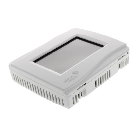
TEC3000 Series On/Off or Floating Fan Coil and Individual
Zone Thermostat Controllers with Dehumidification
Capability
Installation Instructions
TEC3310-xx-xxx, TEC3311-xx-xxx, TEC3312-xx-xxx, TEC3313-xx-xxx,TEC3610-xx-xxx, TEC3611-xx-xxx, TEC3612-xx-xxx, TEC3613-xx-xxx
Applications
The TEC3000 Series On/Off or Floating Fan Coil and Individual Zone Thermostat Controllers are stand-alone and
field-selectable BACnet® MS/TP or N2 networked devices that provide control of the following:
•
local hydronic reheat valves
•
pressure-dependent variable air volume (VAV) equipment with or without local reheat
•
two- or four-pipe fan coils
•
cabinet unit heaters
•
other individual zone equipment using an on/off or floating control input
The networked models feature a field-selectable Building Automation System (BAS) BACnet MS/TP or N2
communication capability that enables remote monitoring and programming for efficient space temperature control.
All models include a USB port configuration that reduces installation time by allowing simple backup and restore
features from a USB drive, which enables rapid cloning of configuration between like units.
Some models have occupancy sensing capability built into the device. These thermostat controllers maximize up to
30% energy savings in high-energy usage commercial buildings, such as schools and hotels, during occupied
times by using additional standby setpoints.
All models feature an intuitive onboard touchscreen UI with backlit display that makes setup and operation quick
and easy. Multiple fan configurations are supported for fan coil equipment types:
•
single-speed
•
multi-speed (two or three discrete speeds)
•
variable-speed/EC motors (0 to 10 VDC control)
Some models support dehumidification on two-pipe fan coil units with reheat, and four-pipe fan coil units with or
without reheat. When no heating is required, the thermostat controller monitors space humidity and activates
dehumidification control as necessary. Heat and/or reheat is used as required to maintain the space temperature.
For optimal dehumidification performance, use a fan coil unit that has a multi-speed or variable-speed fan (VSF).
Refer to the
TEC3000 Series On/Off or Floating Fan Coil and Individual Zone
Thermostat Controllers with Dehumidification Capability
Installation Instructions
*24107876F*
24-10787-6, Rev. F
(barcode for factory use only)
QuickLIT website
for the most up-to-date version of this document.
1
Part No. 24-10787-6, Rev.
Issued July 2018
F
Advertisement
Table of Contents

Related Manuals for Johnson Controls TEC3310


Summary of Contents for Johnson Controls TEC3310
- Page 1 Zone Thermostat Controllers with Dehumidification Part No. 24-10787-6, Rev. Capability Issued July 2018 Installation Instructions TEC3310-xx-xxx, TEC3311-xx-xxx, TEC3312-xx-xxx, TEC3313-xx-xxx,TEC3610-xx-xxx, TEC3611-xx-xxx, TEC3612-xx-xxx, TEC3613-xx-xxx Refer to the QuickLIT website for the most up-to-date version of this document. Applications The TEC3000 Series On/Off or Floating Fan Coil and Individual Zone Thermostat Controllers are stand-alone and field-selectable BACnet®...
-
Page 2: North American Emissions Compliance
IMPORTANT: The TEC3000 Series Thermostat Controller is intended to provide an input to equipment under normal operating conditions. Where failure or malfunction of the thermostat controller could lead to personal injury or property damage to the controlled equipment or other property, additional precautions must be designed into the control system. -
Page 3: Location Considerations
Installing the Thermostat Controller 1. Use a 1/16 in. (1.5 mm) Allen wrench or Johnson Controls® T-4000-119 Allen-Head Adjustment Tool (order separately) to remove the security screw if it is installed on the top of the thermostat controller cover as illustrated in Figure 2. - Page 4 Figure 2: Removing the Security Screw from the Thermostat Controller Cover (Shown without Occupancy Sensor) (Left) and Removing the Thermostat Controller Cover (Right) 3. Align the thermostat controller mounting base on the wall with the security screw on the top and use the base as a template to mark the two mounting hole locations.
- Page 5 Figure 3: Mounting Hole Locations, Dimensions, in. (mm) (Left) and Securing the Thermostat Controller Mounting Base to the Wall (Right) 4-1/16 (103) 3-1/4 (83) Wiring When an existing thermostat controller is replaced, remove and label the wires to identify the terminal functions. Risk of Electric Shock.
- Page 6 IMPORTANT: Use proper ESD precautions during installation and servicing to avoid damage to the electronic circuits of the thermostat controller. To wire the thermostat controller: 1. Strip the ends of each wire 1/4 in. (6 mm) and connect them to the appropriate screw terminals as indicated in Table 2 and Figure 6 or Figure 7.
- Page 7 CPU board and the base board, the model is the TEC3611. 6. Use a 1/16 in. (1.5 mm) Allen wrench or Johnson Controls T-4000-119 Allen-Head Adjustment Tool (order separately) to reinstall the security screw on the top of the thermostat controller cover. See Figure 2 for security screw placement.
- Page 8 Table 2: Terminal Identification (See Figure 6 and Figure 7 for Wiring Diagrams) Terminal Label Function TEC3310, TEC3311, TEC3312, TEC3313 TEC3610, TEC3611, TEC3612, TEC3613 Floating FC/VAV and On/Off FC Floating FC/VAV and On/Off FC 24 V 24 VAC hot from transformer...
- Page 9 Notes: • VAV and 2-pipe systems should connect their valve to the heating output. • Only one transformer is required for each TEC. Figure 6: On/Off Wiring Diagram (See Table 2 for Terminal Identification) Common N.O. Common Common Common CLG C N.C.
- Page 10 Notes: • For VAV and 2-pipe systems, connect the valve to the heating output. • Only one transformer is required for each TEC. Figure 7: Floating Wiring Diagram (See Table 2 for Terminal Identification) Open Close CLG C Open Close Heating FAN H FAN M...
- Page 11 Note: VAV and 2-pipe systems should connect their valve to the heating output. Figure 8: Floating Control (Pressure-Dependent VAV) Floating Actuator Room Temperature Control Thermostat (Minimum and Maximum Position Adjusted on Actuator) HTG O HTG C Figure 9: Floating Control (Pressure-Dependent VAV with Changeover Sensor/Switch) Changeover Supply Air Sensor...
- Page 12 Note: VAV and 2-pipe systems should connect their valve to the heating output. Figure 11: Floating Control Two-Pipe Heating and Cooling Hydronic Valve Control Fan Coil Application HTG O HTG C Room Temperature Control Thermostat Figure 12: Floating Control Two-Pipe Heating and Cooling Hydronic Valve Control with Changeover Fan Coil Application HTG O Optional Water...
-
Page 13: Setup And Adjustments
Note: VAV and 2-pipe systems should connect their valve to the heating output. Figure 14: Floating Control (Floating Two-Pipe and Four-Pipe Fan Coil Applications) Triac Switch Triac Switch Triac Switches HTG O HTG C CLG O CLG C HTG O HTG C Cooling Valve... -
Page 14: Customizing The Home Screen
Figure 17: Thermostat Controller Home Screen The humidity level appears on the home screen if there is a humidity sensor in the unit, or if the thermostat controller has a network override written to it. Customizing the Home Screen Customizing the Home screen settings include: •... - Page 15 Table 3: Touchscreen Icons (Part 2 of 3) Icon Icon Name Description Unit Power Powers the thermostat controller on or off. Note: This icon disables all equipment control, but does not physically power down the unit. Indicates that the thermostat controller detected a supervisory controller and both are online.
- Page 16 Table 3: Touchscreen Icons (Part 3 of 3) Icon Icon Name Description Fan Overrides for Adjusts the fan override between Low, Medium, High, Auto, and Quiet for Multi-speed Fans multi-speed fans. Medium High Auto Quiet Returns the display to the main home screen. Home Returns to the previous screen.
-
Page 17: User Lockout
User Lockout You can select from three different levels of access at the local display to manage functionality through the supervisory controller. This lockout is independent of any display or passcode settings. The existing temporary occupancy capability is unaffected by this feature. User lockout hides the icons that are not operable. The lockout levels are described in Table 4. - Page 18 6. Press Confirm to save locally and on USB. The setting files are named based on the TEC3000 model name, date, and time stamp (for example, TEC3311-00_2015-10-08T1). The files are saved locally and on the USB drive’s root directory. See Troubleshooting if the settings are not backed up correctly. 7.
-
Page 19: Configuring The Thermostat Controller
16. Press to return to the previous screen. 17. Press N2 Address. 18. Enter the N2 address through the keypad. 19. Press Save. Configuring the Thermostat Controller Use the Menu icon on the home screen to access and change the basic operating parameters of the thermostat controller. -
Page 20: Selecting The Heating And Cooling Device Type
Selecting the Heating and Cooling Device Type By default, the thermostat is configured for On-Off (2-position) control. This can be changed to Floating (Incremental) mode when the Unit Type is not set to VAV. For VAV mode, only floating actuators are supported and this option is unavailable. -
Page 21: Setting The Control Mode
For VSF control, the output is configurable for any range between 0 V and 10 V. The parameters are Start Voltage, Full Speed Voltage, and Minimum Command. Start Voltage is the voltage output at which the fan begins running, and Full Speed Voltage is the voltage output at which the fan reaches full speed. Minimum Command is the percentage of the range between the Start Voltage and the Full Speed Voltage. -
Page 22: Configuring The Zone Space Or Equipment Size - Floating Actuators, Multi-Speed Fans, And Variable-Speed Fans Only
• High—Fan is continuously on high • Auto—Fan cycles on demand with the controller entering cooling, heating, or dehumidification modes • Smart—Fan cycles on demand with the controller entering cooling or heating modes during unoccupied periods but is continuously running during occupied and standby periods The Fan Override icon on the home screen is dependent on the fan type. -
Page 23: Dehumidification Control - Fan Coil Only
For automatic changeover, a supply temperature sensor or switch must be connected to the Changeover Sensor (COS) input of the TEC. Changeover Mode must be set to Auto, and Supply Temp Type must be set for Analog Sensor, Cooling N.C. (cooling when switch is closed), or Heating N.C. (heating when switch is closed). When an analog sensor is used, the changeover setpoint can be adjusted. -
Page 24: Temperature Setpoints
To enable dehumidification control: 1. Press the Menu icon. 2. Press Control Setup. 3. Press General. 4. Press Dehum Enable and select Yes. 5. Press to save and to return to the previous screen. This point is also exposed to the BAS through the point DEHUM-EN. To adjust the dehumidification setpoint: 1. -
Page 25: Configuring Occupancy
The four modes of setpoint operation are described in Figure 5. Table 5: Setpoint Operation Mode of Setpoint Details Operation Occ Setpoint Select = This is the default mode and the original mode of operation that the TEC was released with Setpoint Offset and (the next three modes are new). -
Page 26: Selecting Schedule Source
Enumerations may not match the TEC3000 Series On/Off or Floating Fan Coil and Individual Zone Thermostat Controllers with Dehumidification Capability Installation Instructions (Part No. 24-10787-6), TEC3000 Series Proportional Fan Coil and Individual Zone Thermostat Controllers with Dehumidification Capability Installation Instructions (Part No. 24-10788-0), TEC3000 Series Single- or Two-Stage Economizer Thermostat Controllers Installation Instructions (Part No. -
Page 27: Setting The Local Schedule
If the OCC-CONFIG is set to Schedule, the internal schedule commands the LOCAL-OCC object, which sets the Occupancy Schedule command. Note: If you do not have a schedule in the Schedule object and you have the OCC-CONFIG set to Schedule, you can control the unit with the LOCAL-OCC object externally;... - Page 28 5. Select the days to which the schedule should apply. Note that if events are already set for the selected days, they appear in the corresponding event box. If any events conflict between selected days, an asterisk appears in the event box. See Figure 18. 6.
-
Page 29: Overriding The Occupancy Mode
8. Set the time to the time at which the event should occur and press Save. Figure 20: Setting the Event Time (Left) and Viewing the Event Time (Right) 9. Press Save to save the event and press the Return icon to return to the main scheduler screen. Figure 21: Returning to the Main Menu 10. -
Page 30: Enabling Optimal Start
PID is used in conjunction with a Multi-Stage Controller (MSC) for all occupied and standby control. Additionally, the PID features Johnson Controls proprietary PRAC+ (Pattern Recognition Adaptive Control) automatic tuning, which continuously tunes the controller parameters to automatically optimize the control performance to match the equipment and zone. -
Page 31: Configurable Binary Inputs
PRAC+ automatic tuning can also be disabled. When disabled, the controller parameters remain at their last values until automatic tuning is re-enabled. To disable automatic tuning: 1. Press the Menu icon. 2. Press Control Setup. 3. Press Tuning. 4. Press Temp Control Setup. 5. -
Page 32: Aux Control
The Open Door option works in conjunction with a motion sensor, either built into the TEC or connected to another BI configured for Motion NO/NC mode. When the door is open, motion detected by the sensor is ignored. Note that opening the door does not stop an Occupied period started by the motion sensor prior to opening the door. -
Page 33: Commissioning Mode
Commissioning Mode The thermostat controller has a built-in commissioning mode, which is designed to allow you to quickly test equipment wiring and functionality. Commissioning mode temporarily disables the control logic, and allows you to manually command any individual output. Commissioning is designed to be the last step of the installation process after configuring the controller for the equipment being controlled, and the available options in commissioning mode are dependent on the controller configuration. -
Page 34: Menus And Submenus
Menus and Submenus In the following table, the * indicates that the menus depend on your configuration. Table 10: Menus and Submenus (Part 1 of 9) Level 1 Level 2 Level 3 Available Values (LCD Screen Name) (Default Values) Setpoints Occ Cooling Setpoint 72°F (22°C) 55 to 85°F (13 to 30°C) - Page 35 Table 10: Menus and Submenus (Part 2 of 9) Level 1 Level 2 Level 3 Available Values (LCD Screen Name) (Default Values) Schedule Schedule Options — Set Schedule See Scheduling Optimal Start Enable Yes or No Temp Occ Duration 120 minutes 0 to 300 minutes Motion Sensor Timeout 15 minutes...
- Page 36 Table 10: Menus and Submenus (Part 3 of 9) Level 1 Level 2 Level 3 Available Values (LCD Screen Name) (Default Values) Control Setup Fan Off Delay* 30 seconds 0 to 120 seconds (Cont) * Fan coil units only Frost Protection Yes or No Dehumidification Enable* Yes or No...
- Page 37 Table 10: Menus and Submenus (Part 4 of 9) Level 1 Level 2 Level 3 Available Values (LCD Screen Name) (Default Values) Control Setup Humidity Offset 0% RH -15% to 15% RH (Cont) Reset Sensors False True or False Zone Temp Alarm Enabled Yes or No Zone Temp Low Limit 55°F...
- Page 38 Table 10: Menus and Submenus (Part 5 of 9) Level 1 Level 2 Level 3 Available Values (LCD Screen Name) (Default Values) Control Setup Cool Process Range* 40°F 10 to 100°F (-12.22 to 37.77°C) (Cont) *Values only appear when the Temp control equals Manual PID Tuning.
- Page 39 Table 10: Menus and Submenus (Part 6 of 9) Level 1 Level 2 Level 3 Available Values (LCD Screen Name) (Default Values) Equipment Setup General Unit Type 4-Pipe 2-Pipe, 4-Pipe, VAV Heating/Cooling Device Type* Floating On/Off, Floating * Fan coil units only Actuator Stroke Time* 30 seconds 5 to 300...
- Page 40 Table 10: Menus and Submenus (Part 7 of 9) Level 1 Level 2 Level 3 Available Values (LCD Screen Name) (Default Values) Equipment Setup Min Command* 0 to 100% (Cont) * Fan coil units only, variable-speed fan Med Fan Speed On Cmd* 0 to 100% * Fan coil units only, multi-speed fan High Fan Speed On Cmd*...
- Page 41 Table 10: Menus and Submenus (Part 8 of 9) Level 1 Level 2 Level 3 Available Values (LCD Screen Name) (Default Values) System Status Occupancy Source Local Schedule Occupancy BI Temp Occ BI Temp Occ Occ Override Local Schedule BAS Schedule Occupancy Sensor Unit Status Cooling...
-
Page 42: Troubleshooting
An internal sensor has failed on the Order replacement units and return the affected TEC. devices to Johnson Controls under the RMA program. TEC3000 Series On/Off or Floating Fan Coil and Individual Zone Thermostat Controllers with Dehumidification Capability Installation Instructions... - Page 43 Calibration Corrupt Factory calibration data is lost or is not Order replacement units and return the affected installed. devices to Johnson Controls under the RMA program. Changeover Fail The Supply Temperature Sensor is not Follow the same steps as Supply Temp Fail installed, has failed, or has been alarm.
- Page 44 Table 11: Fault List (Part 3 of 3) Faults Probable Causes Solutions Touchscreen Unavailable The touchscreen components have 1. Reboot the controller. failed to initialize. 2. If problems persist, order replacement units and return the affected devices to Johnson Controls under the RMA program. Board Mismatch The baseboard and CPU board are Match the baseboard to its corresponding CPU...
- Page 45 Table 12: Troubleshooting Details (Part 1 of 2) Symptom Probable Causes Solutions The controller displays Idle with a The 2-pipe fan coil/VAV system 1. Check the wiring of the supply temperature Unit Status of Cooling does not have a changeover sensor/switch.
- Page 46 A hardware failure is causing the Order replacement units and return the affected two boards to incorrectly identify devices to Johnson Controls under the RMA themselves. program. The controller displays Controller An internal fault was detected Order replacement units and return the affected Fault.
-
Page 47: Repair Information
UL Listed, File E27734, CCN XAPX7, Under E60730 Industry Canada, ICES-003 Europe CE Mark – Johnson Controls declares that this product is in compliance with the essential requirements and other relevant provisions of the EMC Directive and the RoHS Directive. - Page 48 The performance specifications are nominal and conform to acceptable industry standards. For application at conditions beyond these specifications, consult the local Johnson Controls office. Johnson Controls shall not be liable for damages resulting from misapplication or misuse of its products.