
Related Manuals for Motorola GTR 8000


Summary of Contents for Motorola GTR 8000
- Page 1 System Release 7.13 ASTRO ® INTEGRATED VOICE AND DATA GTR 8000 BASE RADIO November 2012 *6871022P86* 6871022P86-A © 2012 Motorola Solutions, Inc. All rights reserved...
- Page 3 Accordingly, any copyrighted Motorola computer programs contained in the Motorola products described in this document may not be copied or reproduced in any manner without the express written permission of Motorola. © 2012 Motorola Solutions, Inc. All Rights Reserved No part of this document may be reproduced, transmitted, stored in a retrieval system, or translated into any language or computer language, in any form or by any means, without the prior written permission of Motorola Solutions, Inc.
- Page 5 Document History Version Description Date 6871022P86-A First release of the GTR 8000 Base Radio manual. November 2012...
-
Page 7: Table Of Contents
1.5.1 How To Configure The HP2610 Ethernet LAN Switch..............1-6 1.6 Overview For a GTR 8000 Base Radio in a High Performance Data (HPD) Subsystem ........1-6 1.7 Overview for a GTR 8000 Base Radio or GPW 8000 Receiver in Conventional Architectures ......1-8 1.7.1 ASTRO 25 Conventional Base Radio/Receiver ................ - Page 8 3.4.2.1 How to Mount the Base Radio/Receiver ................3-18 3.4.3 Connecting Power ......................... 3-18 3.4.3.1 Connecting Power Cables to a GTR 8000 Base Radio ............3-18 3.4.3.2 DC Power Connection Wire Gauge Calculations for Integrated Voice and Data......3-19 3.4.3.3 DC Power Connection Wire Gauge Calculations for HPD............3-19...
- Page 9 3.4.7.6 GTR 8000 Base Radio – Part 68 Information................ 3-35 3.5 Installation/Troubleshooting Tools ..................... 3-36 3.5.1 Quick Connect RF Coaxial Adapters for GTR 8000 Base Radio Support .......... 3-36 3.6 Device Software Installation Prerequisites ................... 3-37 3.7 Using Software Download........................ 3-39 3.8 Device Installation Using the UNC ....................
- Page 10 5 GTR 8000 Base Radio Optimization......................5-1 5.1 Aligning the Internal Frequency Reference Oscillator ................5-1 5.1.1 GTR 8000 Base Radio Time and Frequency Inputs ................ 5-2 5.2 Equalizing the Battery ........................5-2 5.3 Aligning ASTRO Simulcast (Trunked Operation) ................... 5-3 5.4 Aligning ASTRO/Analog Simulcast (Conventional Operation)..............
- Page 11 5.9.5.7.1 How To Verify UHF Duplexer Isolation ..............5-33 5.9.5.8 UHF Duplexer Post Tuning Checks ..................5-33 5.10 Testing the GTR 8000 Base Radio/GPW 8000 Receiver Performance with a Service Monitor for Integrated Voice and Data ......................... 5-33 5.10.1 Deviation Standards (Digital Operation) ................... 5-34 5.10.2 Monitoring the Power Supply Module..................
- Page 12 9.6.1 How To Replace a Power Amplifier ..................9-18 9.7 Replacing the GTR 8000 Base Radio Backplane ................... 9-21 9.7.1 How To Replace a GTR 8000 Base Radio Backplane ..............9-21 9.8 Replacing a Preselector Filter......................9-27 9.8.1 How To Replace a Preselector Filter..................9-28 9.9 Replacing Transmit Filters (700/800 MHz) ..................
- Page 13 Document History A.1.2 T3-3R Receiver Mute Option Kit ....................A-4 A.1.2.1 T3-3R Receiver Mute Option Kit Parts List................A-5 A.1.3 T4-4R Receiver Mute Option Kit ....................A-6 A.1.3.1 T4-4R Receiver Mute Option Kit Parts List................A-8 A.1.4 Expected Site Performance for T2-2R, T3-3R, and T4-4R Receiver Mute ......... A-9 A.1.5 Tn-nR Receiver Mute Option Kit ....................
- Page 15 Fan Module ..........................2-7 Figure 2-9 Power Supply .......................... 2-7 Figure 2-10 AC and DC Power Distribution in the GTR 8000 Base Radio ............2-9 Figure 2-11 Power Supply Connections (Rear) ....................2-11 Figure 2-12 Preselector Filter (700/800 MHz) ....................2-12 Figure 2-13 Preselector (UHF) ........................
- Page 16 Captive Screws ........................9-18 Figure 9-8 GTR 8000 Power Amplifier RF Cable (Front)................9-20 Figure 9-9 GTR 8000 Base Radio Showing Connections to Backplane Through Backplane Cover......9-21 Figure 9-10 Fan Cable Connector ....................... 9-24 Figure 9-11 EMI Spring Panel Guide Rail Alignment ..................9-25 Figure 9-12 Preselector Filter (700/800 MHz) ....................
- Page 17 Figure B-2 Analog Simulcast Cable in an Open Rack Configuration ..............B-3 Figure B-3 Analog Simulcast Assembly in Rack – GTR 8000 Base Radio Backplane ........... B-4 Figure B-4 Connected Analog Simulcast Cable – GTR 8000 Base Radio Front View..........B-4 Figure B-5 Analog Simulcast Cable –...
- Page 19 GTR 8000 Base Radio/GPW 8000 Receiver Specifications for IV&D (700 and 800 MHz) ....1-14 Table 1-6 GTR 8000 Base Radio/GPW 8000 Receiver FCC Identification for IV&D (700 and 800 MHz) ..... 1-16 Table 1-7 GTR 8000 Base Radio/GPW 8000 Receiver Industry Canada for IVD (700 and 800 MHz)....1-16 Table 1-8 GTR 8000 Base Radio/GPW 8000 Receiver General Specifications for IV&D UHF R1 (380–435 MHz)
- Page 20 Base Radio Diagnostic Options in UEM ..................8-5 Table 8-3 Local Password and SNMPv3 Passphrase Troubleshooting..............8-7 Table 9-1 GTR 8000 Base Radio Field Replaceable Units ................9-1 Table 9-2 GTR 8000 Base Radio Field Replaceable Parts ................9-3 Table 9-3 Individual Replaceable Parts on External Dual Circulator Tray............
- Page 21 4.4.1 — Initial Configuration of a Device Using CSS........................4-3 4.4.6 — CSS Configuration Parameters for the GTR 8000 Base Radio (Trunked Simulcast)..........4-26 4.4.7 — CSS Configuration Parameters for the GTR 8000 Base Radio (Trunked Repeater) ..........4-27 4.4.8 — CSS Configuration Parameters for the GTR 8000 Base Radio (HPD)...............4-28 4.4.9 —...
- Page 23 List of Procedures 1.5.1 — How To Configure The HP2610 Ethernet LAN Switch ....................1-6 3.3.5 — General Floor Mounting Procedure for Cabinets or Racks ..................3-9 3.4.2.1 — How to Mount the Base Radio/Receiver .........................3-18 3.4.4.1 — How to Ground Base Radio/Receiver........................3-23 3.8.1 —...
- Page 24 9.5.1 — How To Replace a Power Supply Fan ........................9-16 9.6.1 — How To Replace a Power Amplifier ...........................9-18 9.7.1 — How To Replace a GTR 8000 Base Radio Backplane....................9-21 9.8.1 — How To Replace a Preselector Filter ..........................9-28 9.9.1 — How To Replace Transmit Filters (700/800 MHz) .....................9-29...
- Page 25 List of Procedures 9.10.1 — How To Replace The Dual Circulator/Isolator Modules ..................9-33 9.11.1 — How To Replace a Duplexer (700/800 MHz) ......................9-36 9.12.1 — How To Replace a Duplexer (UHF) .........................9-37 9.13.1 — How To Replace a Duplexer (VHF) .........................9-40 9.14.1 —...
- Page 27 GTR 8000 Base Radio in the event of failure. Useful Background Information Motorola offers various courses designed to assist in learning about the system. For information, go to http://www.motorolasolutions.com/training to view the current course offerings and technology paths.
- Page 28 Conventional Architecture. ® QUANTAR with a GTR 8000 Base Radio Trunked IP Simulcast Subsystem Remote Site Provides the information required to understand and operate the GTR 8000 ® Base Radio in an ASTRO 25 trunked site. HPD Standalone System - Infrastructure...
-
Page 29: Gtr 8000 Base Radio Description
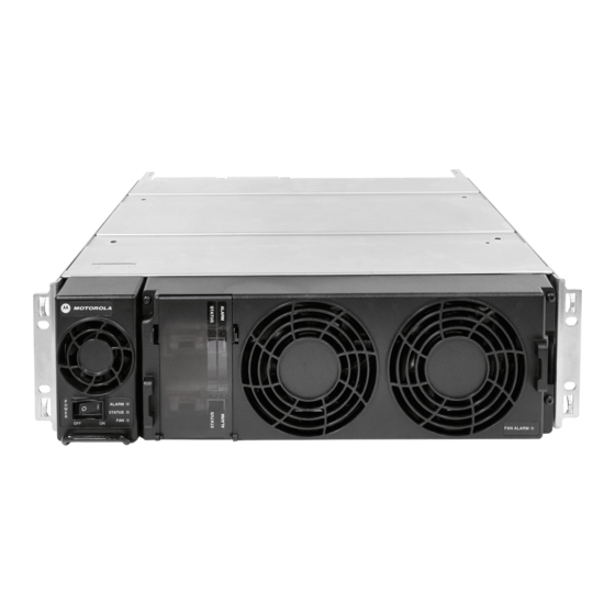
GTR 8000 Base Radio Description This chapter provides a high-level description of the GTR 8000 Base Radio and GPW 8000 Receiver and the function they serve in your system. 1.1 Introduction Figure 1-1 GTR 8000 Base Radio/GPW 8000 Receiver This manual provides information on the standalone GTR 8000 Base Radio and GPW 8000 Receiver and associated applications. -
Page 30: Gpw 8000 Receiver
CSS. The power supply module supports the transceiver module. Radio Frequency Distribution System (RFDS) provides the interface between the receiver and the site antennas. The receiver provides all the receive function of a GTR 8000 Base Radio as a receive-only station in a Conventional Architecture or ASTRO ®... -
Page 31: Supported System Configurations
1.3.1 Supported Frequencies for Trunked IV&D and Conventional Architectures The GTR 8000 Base Radio and GPW 8000 Receiver are available in the following frequency bands: • 700, 800 MHz (700 MHz analog conventional is not available within the U.S.A. or Canada) •... -
Page 32: Supported Frequencies For Hpd
PSC 9600 Site Controllers or base radios other than the GTR 8000 Base Radios. The base radios may be colocated with the site controllers, or be separated (non-colocated) from the site controllers. - Page 33 1.5 Overview For a GTR 8000 Base Radio in a Trunked Single-Site Repeater Configuration Figure 1-2 Single-Site Repeater Configuration 1 If the distance between the first non-colocated base radio and subsequent non-colocated base radios is less than 328 ft. (100 m), a single Ethernet LAN switch can be used to distribute the site controllers call control signaling to those non-colocated base radios.
-
Page 34: How To Configure The Hp2610 Ethernet Lan Switch
1.6 Overview For a GTR 8000 Base Radio in a High Performance Data (HPD) Subsystem The GTR 8000 Base Radio provides the radio frequency (RF) link between the system site controller and the subscriber/mobile radios. The base radio captures inbound signals through external receive (Rx) antennas from the subscriber/mobile radios and then amplifies, filters and demodulates the signals into data packets which are forwarded to the site controller. -
Page 35: Figure 1-4 Gtr 8000 Base Radios In Hpd Remote Site
1.6 Overview For a GTR 8000 Base Radio in a High Performance Data (HPD) Subsystem The site controller receives digitized data payload and control packets from the RNG and routes them to a specified base radio. The base radio extracts the control instructions from the packets and uses them for internal management such as channel frequency assignment. -
Page 36: Overview For A Gtr 8000 Base Radio Or Gpw 8000 Receiver In Conventional Architectures
MSUs so that outbound traffic intended for the MSU does not conflict with inbound random or reserved access traffic from the MSU. 1.7 Overview for a GTR 8000 Base Radio or GPW 8000 Receiver in Conventional Architectures Throughout this manual the term “conventional”... -
Page 37: Analog Conventional Base Radio/Receiver
1.7.2 Analog Conventional Base Radio/Receiver • Standalone repeater • Control station • Receive-only station • Voting • Multicast • Simulcast • Console Control – Monitor Mode – Repeat Control – Frequency Select – Scan Control (supported for Gold Elite console) –... -
Page 38: Power Efficiency Package
– Conventional Base Radio Sites – Conventional Hub Sites 1.8 Power Efficiency Package The GTR 8000 Base Radio or GPW 8000 Receiver is available in a Power Efficiency Package, which provides low standby power consumption (see Table 1-2) functionality for ASTRO ®... -
Page 39: Table 1-2 Standby Power Consumption
1.8 Power Efficiency Package The Power Efficiency Package hardware includes a modified transceiver, power amplifier, power supply, fan, and optional transceiver option card (internal reference) along with additional software configurations through CSS. The following conditions must be met to obtain a power consumption of less than or equal to 35 W: •... -
Page 40: Gtr 8000 Base Radio/Gpw 8000 Receiver Specifications
GTR 8000 Base Radio 1.9 GTR 8000 Base Radio/GPW 8000 Receiver Specifications The following lists the specifications for the GTR 8000 Base Radio and GPW 8000 Receiver. • 1.9.1 GTR 8000 Base Radio/GPW 8000 Receiver Specifications for Integrated Voice and Data (700 and 800 MHz), page 1-12. -
Page 41: Gtr 8000 Base Radio/Gpw 8000 Receiver Specifications For Integrated Voice And Data (700 And 800 Mhz)
1.9.1 GTR 8000 Base Radio/GPW 8000 Receiver Specifications for Integrated Voice and Data (700 and 800 MHz) Table 1-3 GTR 8000 Base Radio/GPW 8000 Receiver General Specifications IV&D (700 and 800 MHz) (cont'd.) General Specifications Operating Altitude Up to 1800 meters (5900 feet) above mean... -
Page 42: Table 1-4 Gtr 8000 Base Radio Transmitter Specifications For Iv&D (700 And 800 Mhz)
GTR 8000 Base Radio Table 1-3 GTR 8000 Base Radio/GPW 8000 Receiver General Specifications IV&D (700 and 800 MHz) (cont'd.) General Specifications Frequency Stability TRAK External Reference Frequency Generation Synthesized Table 1-4 GTR 8000 Base Radio Transmitter Specifications for IV&D (700 and 800 MHz) - Page 43 1.9.1 GTR 8000 Base Radio/GPW 8000 Receiver Specifications for Integrated Voice and Data (700 and 800 MHz) Table 1-5 GTR 8000 Base Radio/GPW 8000 Receiver Specifications for IV&D (700 and 800 MHz) (cont'd.) Receiver Specifications C4FM, FM Modulation (GPW 8000 Receiver) Analog Sensitivity (12 dB SINAD) 12.5 kHz -118 dBm...
-
Page 44: Industry Canada
851-870 MHz Transmitter 2-100 W ABZ89FC5810 792-825 MHz Receiver ABZ89FR5811 1.9.1.1 Industry Canada Table 1-7 GTR 8000 Base Radio/GPW 8000 Receiver Industry Canada for IVD (700 and 800 MHz) IC Approval IC Model Frequency Range Type Power Output Number Number 109AB-T7039 Tx 851–869 MHz, Rx 806–824 MHz... -
Page 45: Gtr 8000 Base Radio/Gpw 8000 Receiver Specifications For Integrated Voice And Data Uhf R1
1.9.2 GTR 8000 Base Radio/GPW 8000 Receiver Specifications for Integrated Voice and Data UHF R1 (380–435 MHz) 1.9.2 GTR 8000 Base Radio/GPW 8000 Receiver Specifications for Integrated Voice and Data UHF R1 (380–435 MHz) Table 1-8 GTR 8000 Base Radio/GPW 8000 Receiver General Specifications for IV&D UHF R1 (380–435 MHz) -
Page 46: Table 1-8 Gtr 8000 Base Radio/Gpw 8000 Receiver General Specifications For Iv&D Uhf R1 (380-435 Mhz)
GTR 8000 Base Radio Table 1-8 GTR 8000 Base Radio/GPW 8000 Receiver General Specifications for IV&D UHF R1 (380–435 MHz) (cont'd.) General Specifications Power Consumption (GTR 8000 Base Radio/GPW 8000 Receiver Standby with Power Efficiency Package) AC: 70 W DC: 35 W Channel Spacing 12.5/25 kHz... - Page 47 1.9.2 GTR 8000 Base Radio/GPW 8000 Receiver Specifications for Integrated Voice and Data UHF R1 (380–435 MHz) Table 1-9 GTR 8000 Base Radio Transmitter Specifications for IV&D UHF R1 (380–435 MHz) (cont'd.) Transmitter Specifications Analog Audio Distortion Less and 2% (1% typical) at 1000 Hz...
-
Page 48: Industry Canada
2-110 W C4FM, FM ABZ89FC4821 2-100 W LSM, H-DQPSK 380–435 MHz ABZ89FR4822 Receiver 1.9.2.1 Industry Canada Table 1-12 GTR 8000 Base Radio/GPW 8000 Receiver Industry Canada for IV&D (UHF R1 380–435 MHz) IC Approval IC Model Frequency Range Type Power Output Number... -
Page 49: Gtr 8000 Base Radio/Gpw 8000 Receiver Specifications For Integrated Voice And Data Uhf R2
1.9.3 GTR 8000 Base Radio/GPW 8000 Receiver Specifications for Integrated Voice and Data UHF R2 (435–524 MHz) 1.9.3 GTR 8000 Base Radio/GPW 8000 Receiver Specifications for Integrated Voice and Data UHF R2 (435–524 MHz) Table 1-13 GTR 8000 Base Radio/GPW 8000 Receiver General Specifications for IV&D UHF R2 (435–524 MHz) -
Page 50: Table 1-14 Gtr 8000 Base Radio Transmitter Specifications For Iv&D Uhf R2 (435-524 Mhz)
GTR 8000 Base Radio Table 1-13 GTR 8000 Base Radio/GPW 8000 Receiver General Specifications for IV&D UHF R2 (435–524 MHz) (cont'd.) General Specifications Power Consumption (GTR 8000 Base Radio/GPW 8000 Receiver Standby with Power Efficiency Package) AC: 70 W DC: 35 W Channel Spacing 12.5/25 kHz... - Page 51 1.9.3 GTR 8000 Base Radio/GPW 8000 Receiver Specifications for Integrated Voice and Data UHF R2 (435–524 MHz) Table 1-14 GTR 8000 Base Radio Transmitter Specifications for IV&D UHF R2 (435–524 MHz) (cont'd.) Transmitter Specifications Analog Audio Distortion Less than 2% (1% typical) at 1000 Hz...
-
Page 52: Table 1-15 Gtr 8000 Base Radio/Gpw 8000 Receiver Specifications For Iv&D Uhf R2 (435-524 Mhz)
GTR 8000 Base Radio Table 1-15 GTR 8000 Base Radio/GPW 8000 Receiver Specifications for IV&D UHF R2 (435–524 MHz) (cont'd.) Receiver Specifications Analog 12.5 kHz 50 or 60 dB (adjustable) Analog 25 kHz 80 dB Analog Audio Response +1, -3 dB from 6 dB per octave de-emphasis;... -
Page 53: Industry Canada
1.9.3.1 Industry Canada 1.9.3.1 Industry Canada Table 1-17 GTR 8000 Base Radio/GPW 8000 Receiver Industry Canada for IV&D (UHF R2 435–524 MHz) IC Approval IC Model Frequency Range Type Power Output Number Number 109AB-T7039 Tx 450–470 MHz, Rx 450–470 MHz... -
Page 54: Table 1-18 Gtr 8000 Base Radio/Gpw 8000 Receiver General Specifications For Iv&D Vhf (136-174 Mhz)
GTR 8000 Base Radio Table 1-18 GTR 8000 Base Radio/GPW 8000 Receiver General Specifications for IV&D VHF (136–174 MHz) (cont'd.) General Specifications DC: C4FM, FM: 460 W max H-DQPSK, LSM: 360 W max Power Consumption (GPW 8000 Receiver) AC: 85 W max... -
Page 55: Table 1-20 Gtr 8000 Base Radio/Gpw 8000 Receiver Specifications For Iv&D Vhf (136-174 Mhz)
1.9.4 GTR 8000 Base/GPW 8000 Receiver Radio Specifications for Integrated Voice and Data VHF (136–174 MHz) Table 1-19 GTR 8000 Base Radio Transmitter Specifications for IV&D VHF (136–174 MHz) (cont'd.) Transmitter Specifications 12.5 kHz 45 dB 25 kHz 50 dB... -
Page 56: Table 1-21 Gtr 8000 Base Radio/Gpw 8000 Receiver Fcc Identification For Iv&D Vhf (136-174 Mhz)
GTR 8000 Base Radio Table 1-20 GTR 8000 Base Radio/GPW 8000 Receiver Specifications for IV&D VHF (136–174 MHz) (cont'd.) Receiver Specifications Analog 12.5 kHz 50 or 60 dB (adjustable Analog 25 kHz 80 dB Spurious and Image Response Rejection 90 dB... -
Page 57: Industry Canada
1.9.4.1 Industry Canada 1.9.4.1 Industry Canada Table 1-22 GTR 8000 Base/GPW 8000 Receiver Radio Industry Canada for IV&D (VHF 136–174 MHz) IC Approval IC Model Frequency Range Type Power Output Number Number 109AB-T7039 Tx 138–174 MHz, Rx 138–174 MHz C4FM, FM... -
Page 58: Table 1-24 Transmitter Specifications For Gtr 8000 Base Radio For Hpd (700 And 800 Mhz)
GTR 8000 Base Radio Table 1-24 Transmitter Specifications for GTR 8000 Base Radio for HPD (700 and 800 MHz) Transmitter Specifications Frequency Range 762–776, 851–870 MHz Power Output* 2-50 W Electronic Bandwidth Full Bandwidth Error Vector Magnitude Spurious and Harmonic Emissions... -
Page 59: Industry Canada
1.9.5.1 Industry Canada Table 1-25 Receiver Specifications for GTR 8000 Base Radio (700 and 800 MHz HPD) (cont'd.) Receiver Specifications Faded Sensitivity 2% Bit Error Rate HT200 (BER) 16 QAM: -94 dBm Faded Sensitivity 1% Bit Error Rate HT200 (BER) -
Page 61: Gtr 8000 Base Radio Theory Of Operation
GTR 8000 Base Radio Theory of Operation For an understanding of the GTR 8000 Base Radio components, review the modules that provide the base radio functionality, the modules that provide RF distribution functionality (RFDS), and the backplane that connects to other modules within the site. -
Page 62: Transceiver Control Board
GTR 8000 Base Radio • Transceiver RF Board: Contains DC power conversion/regulation and performs receiver and exciter functions. • Transceiver Option Card: An optional board that attaches to the control board. Provides an internal 10 MHz frequency reference. For conventional base radio/receiver operation it also provides the analog interfaces and wildcard I/Os. -
Page 63: Exciter
2.1.1.2.1 Exciter 2.1.1.2.1 Exciter The exciter on the XCVR RF board provides the transmitter functions for the base radio. The exciter circuitry generates a low-level, modulated RF signal that passes to the power amplifier. It supports various modulation types as well as bandwidths up to 25 kHz, through software programming. The exciter also provides a controlled output power level to the power amplifier. -
Page 64: Transceiver Option Card Intercom Button
GTR 8000 Base Radio 2.1.1.3.2 Transceiver Option Card Intercom Button There is one intercom button on the front of the transceiver option card, accessible behind the fan module. Pressing the intercom button toggles the intercom function between the ON and OFF states. -
Page 65: Power Amplifier Input/Output Connections
2.1.2.1 Power Amplifier Input/Output Connections The power amplifier (PA) is a forced convection-cooled RF power amplifier. It accepts a low-level modulated RF signal from the transceiver module, and amplifies it for transmission through the site transmit antenna. Also, to complete the Cartesian correction loop (linearization method), it provides a low level RF feedback signal to the transceiver module to achieve the required transmitter linearity. -
Page 66: Function Of The Fan Module
GTR 8000 Base Radio • RF input/feedback (backplane connection). Figure 2-7 Power Amplifier (Backplane Connections) 2.1.3 Function of the Fan Module The fan module provides intermittent forced air cooling for the power amplifier and transceiver modules. The fans are controlled by a thermostat in the modules behind the fan module. The fan module houses two 119 mm axial fans which deliver a total of approximately 160 cubic feet per minute of airflow. -
Page 67: Function Of The Power Supply
2.1.4 Function of the Power Supply Figure 2-8 Fan Module 2.1.4 Function of the Power Supply Figure 2-9 Power Supply 6871022P86-A - November 2012... - Page 68 The power supply controls its own continuously running fan, changing its speed to fast or slow as needed. GTR 8000 Base Radio: If the power supply module is used for the Power Efficiency Package, the power supply fan does not run below a 40 °C air inlet temperature in DC mode with the transmitter in a de-keyed state.
-
Page 69: Ac/Dc Power Distribution - Base Radio
2.1.4.1 AC/DC Power Distribution – Base Radio Figure 2-10 AC and DC Power Distribution in the GTR 8000 Base Radio If present, the base radio operates from AC power as the preferred power source. When AC power is not available, the base radio switches to operate from the DC source. -
Page 70: Battery Temperature Sensor Cable
Motorola recommends that a battery with capacity no larger than 60A-hr be connected to a single charger . In addition to standard sealed lead-acid batteries (valve-regulated lead acid or gel cells), the power supply supports charging of vented lead-acid and NiCd batteries. -
Page 71: Power Supply Module - Backplane Connections
2.1.4.5 Power Supply Module - Backplane Connections 2.1.4.5 Power Supply Module - Backplane Connections Table 2-3 Power Supply Module Backplane Connections Port/Type Description Input only Battery / DC 48 VDC: Power and • Provides the DC input to the power supply when operating from a DC source. Control Signal •... -
Page 72: Backplanes And Card Cages
GTR 8000 Base Radio 2.2 Backplanes and Card Cages Card cages for the GTR 8000 Base Radio are created with a welded and riveted design. Each card cage has a backplane. • See 3.4.5 Connections – Rear (Integrated Voice and Data), page 3-23 3.4.6 Connections –... -
Page 73: Rfds - Preselector (Vhf)
2.3.4 RFDS - Transmit Filter (700/800 MHz) The transmit filter removes any noise in the receive sub-band. The Tx Output from the GTR 8000 Base Radio connects to the Transmit Filters Tx In. The Transmit Filters Tx Out connects the Tx Output or any other RFDS equipment. -
Page 74: Rfds - Duplexer (700/800 Mhz)
GTR 8000 Base Radio Figure 2-15 Transmit Filter (700/800 MHz) 2.3.5 RFDS - Duplexer (700/800 MHz) This optional filter provides the capability to use a single antenna for both transmitter and receiver. Only one transmitter and receiver can be combined. -
Page 75: Rfds - Duplexer (Vhf)
2.3.7 RFDS - Duplexer (VHF) Figure 2-17 Duplexer (UHF) 2.3.7 RFDS - Duplexer (VHF) This optional filter provides the capability to use a single antenna for both transmit and receiver. Only one transmitter and receiver can be combined. 6871022P86-A - November 2012 2-15... -
Page 76: Rfds - External Dual Circulator/Isolator Tray (700/800 Mhz)
2.3.8 RFDS - External Dual Circulator/Isolator Tray (700/800 MHz) An option for the GTR 8000 Base Radio is an External Dual Circulator module which isolates the base radio from the antenna, thus preventing the transmitter from generating intermodulation. The circulator load dissipates reflected power. -
Page 77: Rfds - External Dual Circulator/Isolator Tray (Uhf)
2.3.9 RFDS - External Dual Circulator/Isolator Tray (UHF) An option for the GTR 8000 Base Radio is an External Dual Circulator module which isolates the base radio from the antenna, thus preventing the transmitter from generating intermodulation. The circulator load dissipates reflected power. -
Page 78: Rfds - External Dual Circulator/Isolator Tray (Vhf)
2.3.10 RFDS - External Dual Circulator/Isolator Tray (VHF) An option for the GTR 8000 Base Radio is an External Dual Circulator module which isolates the base radio from the antenna, thus preventing the transmitter from generating intermodulation. The circulator load dissipates reflected power. -
Page 79: Mounting Locations
2.3.11.1 Mounting Locations If the antenna relay is Enabled and it is then disconnected, a failure is generated and logged stating the antenna relay is disconnected. However, the base radio also generates an exciter failure because the antenna relay is controlled and monitored through the exciter module. The exciter failure should be ignored until after the antenna relay failure is corrected. -
Page 80: Figure 2-22 Base Radio Backplane Mounting Location
GTR 8000 Base Radio Figure 2-22 Base Radio Backplane Mounting Location 2-20 6871022P86-A - November 2012... -
Page 81: Figure 2-23 Antenna Relay Module Mounted On Backplane Cover
2.3.11.1 Mounting Locations Figure 2-23 Antenna Relay Module Mounted on Backplane Cover On base radios equipped with the peripheral tray, the antenna relay is mounted on the peripheral tray. 6871022P86-A - November 2012 2-21... -
Page 82: Functional Operation
GTR 8000 Base Radio Figure 2-24 Antenna Relay Module Mounted on Peripheral Tray 2.3.11.2 Functional Operation The antenna relay module contains a relay with a set of normally open and normally closed contacts. The relay coil is controlled by a signal from the transceiver module that connect to Receiver input port Rx-A or the PA deck to a single transmit/receive antenna. -
Page 83: Figure 2-25 Functional Block And Interconnect Diagram For Antenna Relay Module (Bracket Mounting)
2.3.11.2 Functional Operation Figure 2-25 Functional Block and Interconnect Diagram for Antenna Relay Module (Bracket Mounting) 6871022P86-A - November 2012 2-23... - Page 84 GTR 8000 Base Radio Figure 2-26 Functional Block and Interconnect Diagram for Antenna Relay Module (Peripheral Tray Mounting) 2-24 6871022P86-A - November 2012...
-
Page 85: Gtr 8000 Base Radio Installation
3.1.1 Equipment Installation Process Overview Process Steps Prepare the site to comply with the Motorola requirements and specifications for the equipment, as listed in the Standards and Guidelines for Communication Sites manual. Other codes and guidelines that may apply to the location must also be met. -
Page 86: General Safety Precautions
• Do not operate the radio transmitters unless all RF connectors are secure and all connectors are properly terminated. • All equipment must be properly grounded in accordance with the Motorola Standards and Guidelines for Communications Sites manual and specified installation instructions for safe operation. -
Page 87: Figure 3-1 Warning Label On Hot Modules
Figure 3-1 Warning Label on Hot Modules All Tx and Rx RF cables' outer shields must be grounded per Motorola Standards and Guidelines for Communications Sites manual requirements. DC input voltage shall be no higher than 60VDC. This maximum voltage shall include consideration of the battery charging "float voltage"... -
Page 88: Dc Mains Grounding Connections
GTR 8000 Base Radio All Tx and Rx RF cables shall be connected to a surge protection device according to the Motorola Standards and Guidelines for Communications Sites manual. Do not connect Tx and Rx RF cables directly to outside antenna. -
Page 89: Replaceable Batteries
Equipment racks should only be lifted without the use of lifting equipment when sufficient personnel are available to ensure that regulations covering health and safety are not breached. Motorola recommends the use of an appropriate powered mechanical lifting apparatus for moving and lifting the equipment racks. In addition to these points, refer to and comply with any local regulations that govern the use of lifting equipment. -
Page 90: Figure 3-2 Lengths And Angles For Lifting Using The Eyenuts
GTR 8000 Base Radio Do not use the eyenuts if damage is apparent. Contact Motorola for replacements. Use all four eyenuts when lifting the equipment rack. The minimum distance from each eyenut to the lifting point must be 1.2 meters (47.2 in). Using a shorter length than that specified could cause the eyenuts to fail. This figure shows the minimum lengths and proper lifting angles using the eyenuts. -
Page 91: General Installation Standards And Guidelines
Additionally, review the installation information in the Standards and Guidelines for Communication Sites manual for more details, including: • Equipment installation • Antenna installation You should also review installation information specifically for GTR 8000 Base Radios and subsystems in 3.4 GTR 8000 Base Radio Hardware Installation, page 3-16. -
Page 92: General Equipment Inspection And Inventory Recommendations
3.3.2 General Equipment Inspection and Inventory Recommendations Motorola recommends that an inventory of all equipment is taken with a Motorola representative to ensure that the order is complete. Carefully inspect all equipment and accessories to verify they are in good condition. Promptly report any damaged or missing items to a Motorola representative. -
Page 93: General Placement And Spacing Recommendations
(ASHRAE) standards. Also adhere to any local regulations that apply to the installation. • Locate the system in an area that is free of dust, smoke, and electrostatic discharge (ESD). • See the Motorola Standards and Guidelines for Communication Sites manual for details on these space requirements. -
Page 94: General Bonding And Grounding Requirements
This bar provides electrical continuity between all bonds and ground wire with a current carrying capacity equal to or exceeding that of a 6 AWG copper wire. See the Motorola Standards and Guidelines for Communication Sites manual for more information on proper bonding and ground at a site. -
Page 95: General Power Guidelines And Requirements
• Verify that all cables are properly labeled to match System-specific configuration documentation provided by Motorola. • Ensure that cables do not exceed the minimum bend radius as outlined in the Motorola Standards and Guidelines for Communication Sites manual. For more information on cabling guidelines, see the documentation supplied with components from each equipment manufacturer. -
Page 96: General Breaker Recommendations
GTR 8000 Base Radio • All AC power equipment and electrical components must conform to National Electrical Manufacturers Association (NEMA) and National Electrical Code (NEC). These must also be listed by an NRTL. • A surge arrestor, designed to protect equipment systems from a 120/240 V service and load center, is placed on the power feed ahead of all individual load center circuit breakers. -
Page 97: General Electrostatic Discharge Recommendations
3.3.9 General Electrostatic Discharge Recommendations Electronic components, such as circuit boards and memory modules, can be extremely sensitive to electrostatic discharge (ESD). Motorola recommends that an antistatic wrist strap and a conductive foam pad be used when installing or upgrading the system. -
Page 98: General Installation/Troubleshooting Tools
GTR 8000 Base Radio 3.3.12 General Installation/Troubleshooting Tools If information is needed regarding where to obtain any of the equipment and tools listed, contact the Motorola System Support Center (SSC). See 8.5 Using Motorola System Support Center (SSC), page 8-8. -
Page 99: Technical Support For Installation
3.3.13 Technical Support for Installation Technical support is available from the site-specific documents provided by the Field Engineer or Motorola Field Representative for the system, one of the Motorola System Support Center (SSC), or qualified subcontractors. -
Page 100: Site-Specific Information
GTR 8000 Base Radio 3.3.13.1 Site-Specific Information When systems are staged by the Motorola Center for Customer Solution Integration (CCSI), site-specific system documentation is created to document how the system was staged. The Field Engineer assigned to the system creates all of the site-specific information including the following: •... -
Page 101: Rack Mounting The Gtr 8000 Base Radio
3.4.2 Rack Mounting The GTR 8000 Base Radio For the cabinet version, in the event that an eye nut needs to be replaced, at least 2 feet access to both sides of the cabinet is preferable, so that both side panels can be removed. -
Page 102: How To Mount The Base Radio/Receiver
Lift the base radio/receiver into place on the rack using the pins on the brackets to properly line up the device. Attach the two brackets to the rack: a. For a Motorola modular rack, use M6x1x10 thread forming screws with black finish. b. For a Motorola open rack, use 1224x5/8 thread forming screws (zinc plated). -
Page 103: Dc Power Connection Wire Gauge Calculations For Integrated Voice And Data
* = The actual current value can be calculated from the power consumption value in the specifications tables. See 1.9 GTR 8000 Base Radio/GPW 8000 Receiver Specifications, page 1-12. To determine the maximum length of wire for wire other than 2 AWG, the following relationship can be used: •... -
Page 104: Table 3-4 Power Connection Wire Gauge Maximum Distances For Hpd
GTR 8000 Base Radio 48 VDC system), the current will be up to 9.5 A. Use of smaller gauge wire would reduce this length depending on the resistance of the wire. To determine the maximum length of wire for wire other than 2 AWG, the following relationship can be used: •... -
Page 105: Mounting The Battery Temperature Sensor
Voltage is proportional to the battery temperature and is used by diagnostic circuitry in the power supply module. The 40-foot cable can be extended to a total length of 190 feet using 50-foot extensions (Motorola part number 3084827Y04. See 8.5 Using Motorola System Support Center (SSC), page... -
Page 106: Grounding The Gtr 8000 Base Radio
GTR 8000 Base Radio Figure 3-6 Battery Temperature Sensor Example 2 3.4.4 Grounding The GTR 8000 Base Radio Detailed grounding information is beyond the scope of this manual. See the Standards and Guidelines for Communication Sites manual for detailed information about grounding and lightning protection. -
Page 107: How To Ground Base Radio/Receiver
3.4.4.1 How to Ground Base Radio/Receiver When rack installations have a primary rack and one or more expansion racks, all these racks must be connected to the same Sub System Ground Bus Bar (SSGB) (and no other rack connected to the SSGB). This is to ensure surge events do not produce ground potential differences that will affect signals between the racks. -
Page 108: Figure 3-8 Base Radio/Receiver Integrated Voice & Data Backplane
GTR 8000 Base Radio Figure 3-8 Base Radio/Receiver Integrated Voice & Data Backplane Table 3-5 Base Radio/Receiver Backplane Connections for Integrated Voice & Data Port / Port / Type Device it connects to: Description Type SC-A port, Site LAN switch... - Page 109 ASTRO ® 25 simulcast over the air. This input is used in conjunction with EXT FREQ REF option 1. * See 5.1.1 GTR 8000 Base Radio Time and Frequency Inputs, page 5-2. 6871022P86-A - November 2012 3-25...
-
Page 110: Connections - Rear (Hpd)
GTR 8000 Base Radio The EXT FREQ REF input on the rear of the device is high impedance. An external termination is needed to properly terminate the cable connected to the input. It is recommended that a BNC "T" and a 50 Ohm BNC termination be connected to the input to terminate the cable. -
Page 111: Connections - Front
3.4.7 Connections – Front Table 3-6 Base Radio Backplane Connections for HPD (cont'd.) Port / Port / Type Device it connects to: Description Type Rx-A, BNC Receive line A RF coax to receive path for Rx antenna. Rx-B, BNC Receive line B RF coax to receive path for antenna B. -
Page 112: Figure 3-10 Base Radio/Receiver - Front
GTR 8000 Base Radio Figure 3-10 Base Radio/Receiver – Front The Transceiver Option Card is an optional board that attaches to the control board of a base radio or receiver. The board provides an internal 10 MHz frequency reference. For conventional base radio/receiver operation, it provides the analog interfaces and wild card I/Os. - Page 113 3.4.7 Connections – Front Table 3-7 Transceiver Connections - Front (cont'd.) Connects to This XCVR Port / Type Description Device/Port Microphone port, RJ-45 Microphone, RJ-45 port Used to connect to a microphone with PTT button. Use microphone kit GMMN4063B. Speaker port, RJ-9 External Speaker, RJ-9 Used to connect to an amplified port...
-
Page 114: System Connector Ports (Conventional)
* See 5.1.1 GTR 8000 Base Radio Time and Frequency Inputs, page 5-2. For information about conventional functions and topologies supported by the base radio/receiver, see the Conventional Operations manual. Note that the base radio/receiver can be IP managed while using the 2- or 4-wire/V.24 interface for channel traffic. - Page 115 3.4.7.1 System Connector Ports (Conventional) Table 3-8 50–Pin System Connector Pin-Outs (Conventional) (cont'd.) Pin # Signal Type Function Note Input Aux In 12 – Opto-Isolated In - Current flow to Activate Input Aux In 13 For future use Pull To Ground To Activate Aux Out 12 Output Low Impedance to Ground When...
- Page 116 GTR 8000 Base Radio Table 3-8 50–Pin System Connector Pin-Outs (Conventional) (cont'd.) Pin # Signal Type Function Note Aux In 11 + Input Opto-Isolated In - Current flow to Activate Aux In 12 + Input Opto-Isolated In - Current flow to...
-
Page 117: Wireline Port Pin-Outs
3.4.7.2 Wireline Port Pin-Outs Figure 3-11 50–Pin System Connector Pin-Outs (Conventional) 3.4.7.2 Wireline Port Pin-Outs The Wireline port is an RJ-45 connector and can accommodate up to 8 pins. Table 3-9 Wireline Port Pin-Outs Auxiliary 2-Wire 4-Wire 4-Wire Signal Name Pin # Connection Connection... -
Page 118: Microphone Port Pin-Outs
GTR 8000 Base Radio 3.4.7.3 Microphone Port Pin-Outs The Microphone port is an RJ-45 connector that provides the interface for a microphone. Table 3-10 Microphone Port Pin-Outs Signal Name Pin # Reserved Reserved MIC_PTT MIC_AUDIO Reserved Reserved Reserved Figure 3-13 Microphone Port Pin-Outs 3.4.7.4 Speaker Port Pin-Outs... -
Page 119: Port Pin-Outs
Input Output 3.4.7.6 GTR 8000 Base Radio – Part 68 Information This section applies when the base radio/receiver is equipped with the optional wireline interface circuitry contained on the OCXO Transceiver Option Card (Option CA01506AA or TCXO Transceiver Option Card (Option CA01953). -
Page 120: Installation/Troubleshooting Tools
Base Radio Support The GTR 8000 Base Radio employs a number of "QN" & "QMA" Quick Connect RF connectors in its design. The following RF adapters are available from Motorola and can be used to connect test equipment to the various station devices for troubleshooting purposes. -
Page 121: Device Software Installation Prerequisites
3.6 Device Software Installation Prerequisites Table 3-13 Quick Connect RF Coaxial Adapters for GTR 8000 Base Radio Support (cont'd.) Type Adapter / Connector description Motorola Part Number 2871002H01 Right Angle Male QN cable plug for RG-400 coax 2886067Y01 Right Angle Male QN cable plug for RG-213... - Page 122 GTR 8000 Base Radio Obtain the following values from the system administrator: • line interface number • ZC site link path 1 IP address • ZC site link path 2 IP address • Host name to access the UNC server application using SSH (username>@IP address> format) •...
-
Page 123: Using Software Download
This step is applicable to systems with AAA Servers, Domain Controllers, or Syslog Servers. To use the VoyenceControl component of Motorola’s centralized configuration application for any of the site device procedures, you need to set up the Unified Network Configurator (UNC). Depending on your organization’s policies, you may also need to implement a secure protocol between the UNC and the site device. - Page 124 GTR 8000 Base Radio For information on how to configure the secure or clear SWDL transfer mode, see the Unified Network Configurator manual and “Device Security Configuration” in the CSS Online Help. Software Download can be accomplished in two ways: •...
-
Page 125: Device Installation Using The Unc
3.8 Device Installation Using the UNC SWDL operation can be fault managed through UEM, syslog, local SWDL log files, user messages, and device reports. For further information on SWDL, see the Software Download manual. The operating software can also be loaded using the UNC. See the Unified Network Configurator manual to perform single device software downloads (ruthless download) to the devices. -
Page 126: Discovering A Device With The Unc
GTR 8000 Base Radio Process Steps Discover the device in the UNC. See 3.8.1 Discovering a Device with the UNC, page 3-42. Logging in to the UNC Server Application Using PuTTY. See the Securing Protocols with SSH manual. Load the Operating System images to the UNC. See 3.8.2 Loading Device OS Images to the UNC, page... - Page 127 3.8.1 Discovering a Device with the UNC Enter: http://ucs-unc0<Y>.ucs:9443/UNCW in the Address field. Where <Y> is the number of the UNC server (01 for primary core UNC server, and 02 for backup core UNC server). Step result: The UNC Wizard launches and a login dialog box appears. Type the administrative username and password.
-
Page 128: Loading Device Os Images To The Unc
Step result: The device sites are listed, which means they are available for channel configuration. 3.8.2 Loading Device OS Images to the UNC Prerequisites: This procedure requires the Motorola device OS Image CDs. Locate the Transport OS Image media that is packaged with the Network Management DVDs. When and where to use: This procedure loads the Operating System (OS) images for the devices for distribution through the Unified Network Configurator (UNC). -
Page 129: Loading Software To A Device
Select Load new OS images from the menu. Press ENTER. Step result: A message appears indicating there are two methods for loading OS Images. Insert the Motorola Device OS Images CD into the CD/DVD-ROM drive of the server. Step result: The drive light starts blinking on the server. -
Page 130: Enabling Ftp Service
GTR 8000 Base Radio 3.8.3.1 Enabling FTP Service Prerequisites: Prior to installing the OS software, FTP services must be enabled. Procedure Steps Launch an SSH terminal server session in PuTTY to access the UNC Server Administration menu. See the Securing Protocols with SSH manual. -
Page 131: Figure 3-15 Voyencecontrol Welcome Page
3.8.3.2 Transferring and Installing the OS Image On the PNM client where you set up VoyenceControl, double-click the UNC shortcut on the desktop. You can also paste the following address into IE web browser: http://ucs-unc0<Y>.ucs, where <Y> is the number of the UNC server (01 for primary core UNC server, and 02 for backup core UNC server). -
Page 132: Figure 3-16 Voyencecontrol Login Window
GTR 8000 Base Radio Click the launch VoyenceControl ™ link. Step result: VoyenceControl client session launches with the login window. Figure 3-16 VoyenceControl Login Window Enter the User ID and Password. Click OK. Step result: The VoyenceControl Dashboard appears. Figure 3-17 VoyenceControl Dashboard In the left navigation pane, expand Networks, ASTRO 25 Radio Network, then Views. - Page 133 3.8.3.2 Transferring and Installing the OS Image Double click Motorola <device> from the navigation pane. Step result: The view opens and all currently discovered devices appear. Select Tools → OS Inventory from the menu. You can also press F9 to select the OS Inventory.
-
Page 134: Inspecting Device Properties For Transferred And Installed Software
GTR 8000 Base Radio 12 Select the image for this device from the Selected Image section. You can ignore the Install and Copy check boxes. Step result: This populates the Image Info tab and informs the application which image to use. -
Page 135: Disabling Ftp Service
3.8.3.4 Disabling FTP Service Procedure Steps From the Device view, right click the device, select Pull, then Pull Hardware Spec. Step result: The current software version information is updated in the UNC. Skip this step if a Pull All or Pull Hardware Spec has already occurred. From the Device view, right click on the device, then choose Properties. - Page 136 GTR 8000 Base Radio Procedure Steps Launch an SSH terminal server session in PuTTY to access the UNC Server Administration menu. See the Securing Protocols with SSH manual. Step result: The UNC Server Administration menu appears. Select Unix Administration from the menu. Press ENTER.
-
Page 137: Gtr 8000 Base Radio Configuration
• Updating factory-installed base radio application software • Setting parameters in a configuration file stored on the GTR 8000 Base Radio that impacts both base radio and RF Distribution System (RFDS) functionality. This chapter details configuration procedures relating to the base radio. -
Page 138: Security/Authentication Services
GTR 8000 Base Radio Process Steps Use the Unified Network Configurator Discovery Wizard to: • Discover the devices. • Upload configurations for the devices. • Generate changes for non-compliant devices. Approve jobs (if any). 4.3 Security/Authentication Services If the device supports SNMPv3 protocol, a pop-up dialog box appears displaying the SNMPv3 Password Prompt when logging into a device through Configuration/Service Software (CSS) using an Ethernet connection. -
Page 139: Configuring A Device Using Css
4.4 Configuring a Device Using CSS Figure 4-2 CSS Login Banner 4.4 Configuring a Device Using CSS This section covers configuration of a device using the Configuration/Service Software (CSS). If you do not know the IP address for the device, it is available through a serial port connection in the Tools →... -
Page 140: Connecting Through A Serial Port Link
Continue to one of the following depending on the type of device you are configuring: • 4.4.6 CSS Configuration Parameters for the GTR 8000 Base Radio (Trunked Simulcast), page 4-26 • 4.4.7 CSS Configuration Parameters for the GTR 8000 Base Radio (Trunked Repeater), page 4-27. - Page 141 4.4.2 Connecting Through a Serial Port Link When and where to use: Connecting through a serial port link is used to set the IP address of the device and to set the serial security services. All other device function and feature configurations are performed via an Ethernet port connection in the CSS. Procedure Steps Connect a serial cable to a laptop or PC running the CSS application, and the serial connector located on the device's module.
-
Page 142: Serial Connection Configurations
GTR 8000 Base Radio Figure 4-3 CSS Login Banner Then... If... If a domain controller is available on the network... Type the Username and Password for your RADIUS service user account that is assigned to the netwadm group in Active Directory. (The default user is serviceuser.) -
Page 143: Setting The Device Ip Address And Pairing Number Using Css
4.4.3.1 Setting the Device IP Address and Pairing Number Using CSS 4.4.3.1 Setting the Device IP Address and Pairing Number Using Prerequisites: Ensure that you have the required credentials information (local service account password and elevated privileges password) to configure the site devices before proceeding. The user credentials information includes both the current and new credentials. -
Page 144: Pairing To A Comparator
GTR 8000 Base Radio Procedure Steps Connect to the device using Configuration/Service Software (CSS) through a serial port link. See 4.4.2 Connecting Through a Serial Port Link, page 4-4. Select Tools → Set IP Address/BR_CM Pairing Number from the menu. -
Page 145: Serial Security Services Using Css
4.4.3.3 Serial Security Services Using CSS 224.100.102.nnn, where nnn is: 100 + (2 * channel number) - 1 The Base Radio/Comparator Pairing Number is not used for circuit (V.24 or 4-wire/V.24 hybrid link) configurations. 4.4.3.1 Setting the Device IP Address and Pairing Number Using CSS, page 4-7 on how to set the pairing number. -
Page 146: Resetting Snmpv3 User Credentials To Factory Defaults Using Css
To obtain the keys for resetting either password or SNMPv3 passphrases for the device, contact Motorola Solutions Customer Support. Changing to the incorrect user credentials may lead to not being able to access the device through CSS or SSH. -
Page 147: Connecting Through An Ethernet Port Link
4.4.4 Connecting Through an Ethernet Port Link Procedure Steps Connect to the device using Configuration/Service Software (CSS) through a serial port link. See 4.4.2 Connecting Through a Serial Port Link, page 4-4. Select Security → SNMPv3 Configuration → Reset SNMPv3 Configuration (Serial) from the menu. Step result: The Reset SNMPv3 Configuration dialog box opens. - Page 148 GTR 8000 Base Radio Normally the computer is connected to the appropriate LAN switch either locally or remotely through the network. Do not connect directly to a device unless downloading the software individually to that device. b. Start the computer.
-
Page 149: Figure 4-4 Snmpv3 Security Level Option Prompt
4.4.4 Connecting Through an Ethernet Port Link If... Then... For a site controller or RDM, select Set IP Address/Box Number. 3. Read the IP address from the Device IP Address field. 4. Re-establish an Ethernet connection and repeat steps 1 through 4. 5. -
Page 150: Ethernet Connection Configurations
GTR 8000 Base Radio The front panel Ethernet port on GTR 8000 Base Radios have a fixed IP address (192.168.1.1). However the Ethernet MAC ID for each front panel connection is unique to each base radio. A communication error can occur when configuring multiple base radios through the front panel Ethernet port. -
Page 151: Setting The Date And Time Using Css
4.4.5.2 Setting the Date and Time Using CSS Procedure Steps Connect to the device using Configuration/Service Software (CSS) through an Ethernet port link. See 4.4.4 Connecting Through an Ethernet Port Link, page 4-11. Select Service → BR/CM Pairing Number from the menu. Enter the pairing number. - Page 152 GTR 8000 Base Radio When and where to use: This procedures changes the SNMPv3 configuration and user credentials from CSS on a selected device in the site. For more information on this feature, see the SNMPv3 manual. During installation this is done through an Ethernet cable connected directly to the Ethernet port of the device.
- Page 153 4.4.5.3 Changing SNMPv3 Configuration and User Credentials Using CSS If... Then... 4. Click OK. Step result: The DNS information of the device automatically appears in the Device IP Address field. 5. Continue with step 5. Click OK. Step result: A connection is made with the selected device, and the entered SNMPv3 admin passphrases are authenticated and the Configure SNMPv3 Users dialog box appears.
-
Page 154: Adding Or Modifying An Snmpv3 User Using Css
GTR 8000 Base Radio To change the Authentication Passphrase for the selected SNMPv3 user (if applicable to the selected security level), type the password into the Old Passphrase Field in the Authentication Passphrase form of the Configure SNMPv3 Users dialog box. -
Page 155: Performing An Snmpv3 Connection Verification Using Css
4.4.5.3.2 Performing an SNMPv3 Connection Verification Using CSS Procedure Steps In the CSS, log in using the appropriate credentials. Step result: The Configure SNMPv3 Users dialog box appears. To create, delete, or update the selected SNMPv3 user, use one of the following steps: If... -
Page 156: Configuring Dns Using Css
GTR 8000 Base Radio Procedure Steps Connect to the device using Configuration/Service Software (CSS) through an Ethernet port link. See 4.4.4 Connecting Through an Ethernet Port Link, page 4-11. When the passphrase prompt screen opens, select configured security level and enter the required passphrases. -
Page 157: How To Configure Dns Using Css
4.4.5.4.1 How to Configure DNS Using CSS Table 4-2 Conventional Comparator System Name Variables (cont'd.) Variable Description siteXXXX The logical Site ID (as configured on the Site configuration screen), where XXXX is a number between 2000 and 2255. csubYY The number of the Conventional Subsystem, where YY is a number between 1 and 47. -
Page 158: Customizing The Login Banner Using Css
GTR 8000 Base Radio Enter the Requested DNS Server IP address for the Primary, Secondary, and Tertiary DNS servers. The Primary Row Status must be enabled before the Secondary row is ungrayed. The secondary row status must be enabled before the Tertiary row is ungrayed. See Table 4-1. -
Page 159: Setting The Swdl Transfer Mode Using Css
4.4.5.6 Setting the SWDL Transfer Mode Using CSS Procedure Steps Connect to the device using Configuration/Service Software (CSS) through an Ethernet port link. See 4.4.4 Connecting Through an Ethernet Port Link, page 4-11. Select Security → Device Security Configuration → Remote Access/Login Banner (Ethernet) from the menu. -
Page 160: Setting The Ntp Server Settings
GTR 8000 Base Radio Select Security → Device Security Configuration → Remote Access/Login Banner (Ethernet) from the menu. Step result: The Remote Access/Login Banner screen appears displaying the Remote Access Configuration tab. Figure 4-6 Remote Access Configuration Tab In the Software Download Transfer Mode (Requested) field, choose either Ftp (clear) or Sftp (secure). -
Page 161: Setting Up The Local Password Configuration Using The Css
4.4.5.8 Setting Up the Local Password Configuration Using the CSS When the IP addresses exceeds the total, removing IP addresses allows the UEM to be identified as the current manager and can handle traps for the device. 4.4.5.8 Setting Up the Local Password Configuration Using the CSS When and where to use: This procedure describes how to set the complexity requirements and controls for the local service account password. -
Page 162: Css Configuration Parameters For The Gtr 8000 Base Radio (Trunked Simulcast)
4.4.1 Initial Configuration of a Device Using CSS, page 4-3. For configuration parameters on each field for a trunked simulcast GTR 8000 Base Radio, see "Multi-Site or Simulcast Subsystem" in the CSS Online Help. Process Steps Connect to the base radio through an Ethernet port link and then read the configuration file from the base radio. -
Page 163: Css Configuration Parameters For The Gtr 8000 Base Radio (Trunked Repeater)
Radio (Trunked Repeater) Prerequisites: Before proceeding with this process, complete the initial configuration of the device in . For configuration parameters for a trunked Repeater GTR 8000 Base Radio, see "Repeater Site Subsystem" in the CSS Online Help. Process Steps Connect to the base radio through an Ethernet port link and then read the configuration file from the base radio. -
Page 164: Css Configuration Parameters For The Gtr 8000 Base Radio (Hpd)
4.4.8 CSS Configuration Parameters for the GTR 8000 Base Radio (HPD) Prerequisites: Before proceeding with this proccess, complete the initial configuration of the device in . For configuration parameters for an HPD GTR 8000 Base Radio, see "HPD Remote/Expandable Site" in the CSS Online Help. Process Steps 4-28... - Page 165 4.4.8 CSS Configuration Parameters for the GTR 8000 Base Radio (HPD) Connect to the base radio through an Ethernet port link and then read the configuration file from the base radio. 4.4.4 Connecting Through an Ethernet Port Link, page 4-11.
-
Page 166: Css Configuration Parameters For The Gtr 8000 Base Radio (Conventional)
Before proceeding with this process, complete the initial configuration of the device in . For configuration parameters for a conventional GTR 8000 Base Radio, see the following in the CSS Online Help: • Analog-only, Digital-only, or Mixed Mode GTR 8000 Base Radio: Conventional Site - ASTRO 7.12 and Later •... -
Page 167: Configuring Tx Power Values And Battery Type
4.4.10 Configuring Tx Power Values and Battery Type 11 Click Network Services Configuration in the System tree and complete the fields on the three tabs. For configuration details for RADIUS Services, see the Authentication Services manual. For configuration details for SYSLOG Services, see the Centralized Event Logging, manual. 12 Click Password Configuration in the System tree and complete the fields. -
Page 168: Setting Rmc System Gain
When and where to use: The RMC system gain must be set up according to your organizations GTR 8000 Base Radio configuration. For standalone base radios, calculate and enter a value for system gain. Calculate the system gain from the receiver multicoupler input to the base radio Rx input. -
Page 169: Using Voyencecontrol To Configure Centralized Authentication On Devices
Select Configuration from the navigation tree in the left pane. Select the Receive Multicoupler (RMC) Configuration tab. In the GTR 8000 Configuration field, select GTR 8000 Base Radio Standalone. Enter a dB value in the System Gain field. Save your RMC configuration to an archive on your local or network drive by selecting File → Save or File →... - Page 170 GTR 8000 Base Radio Process Steps Configure Domain Name Service (DNS) on the device. See Chapter 7, “Configuring DNS on RF Site and VPM Devices Using VoyenceControl” in the Authentication Services manual. Configure Authentication Sources for the device. See Chapter 7, “Configuring Authentication Sources for RF Site and VPM Devices Using VoyenceControl in the Authentication Services manual.
-
Page 171: Gtr 8000 Base Radio Optimization
GTR 8000 Base Radio Optimization Your Motorola Field Representative or Motorola System Support Center (SSC) can advise you on optimization activities required for your system, if any. See 8.5 Using Motorola System Support Center (SSC), page 8-8. This chapter contains optimization procedures and recommended settings relating to GTR 8000 Base Radio. -
Page 172: Gtr 8000 Base Radio Time And Frequency Inputs
GTR 8000 Base Radio 5.1.1 GTR 8000 Base Radio Time and Frequency Inputs A variety of external time and frequency inputs can be provided to the base station for normal operation or for Internal Frequency Reference Oscillator alignment. The following table provides a list of acceptable input signal types and levels for each base radio input port. -
Page 173: Aligning Astro Simulcast (Trunked Operation)
5.3 Aligning ASTRO Simulcast (Trunked Operation) See Base Radio Service Help > Service Screens > Alignment Screens in the CSS Online Help for the alignment procedures. Some batteries do not require equalization. See the battery manufacturer recommendations. 5.3 Aligning ASTRO Simulcast (Trunked Operation) ASTRO ®... -
Page 174: Aligning Tx Wireline
Model 92E with BNC input, or Aeroflex 3900 Series Service Monitor using the spectrum analyzer function • Torque driver capable of delivering 12 in -lbs of torque and 10 mm deep well socket • Tuning probe - Motorola Part No. 3082059X01, p/o TRN4083A tuning kit • Flat-blade screwdriver An R2600 Communications Analyzer can both generate and measure simultaneously. -
Page 175: Vhf Tuning Procedures
5.8.1 VHF Tuning Procedures 5.8.1 VHF Tuning Procedures 5.8.1.1 Calculating Proper VHF Alignment Frequency Use either 5.8.1.1.1 Calculating The VHF Alignment Frequency For a Single Receive Frequency, page 5-5 5.8.1.1.2 Calculating The VHF Alignment Frequency for Multi Receive Frequencies, page 5-5 to calculate the VHF alignment frequency to be generated by the signal generator. -
Page 176: Preparing The Equipment For Vhf Alignment
GTR 8000 Base Radio Procedure Steps From the site documentation or the CSS, note the receive frequency for each channel supported by the base radio/receiver. Calculate a midpoint frequency as follows: = (F ) ÷ 2 highest lowest Using F in place of the base radio/receiver receive frequency, perform steps 3 and 4 from 5.8.1.1.1... -
Page 177: Figure 5-1 Preselector Tuning - Vhf
5.8.1.3 VHF Tuning Procedure Figure 5-1 Preselector Tuning — VHF 6871022P86-A - November 2012... -
Page 178: Tuning The Vhf Preselector
GTR 8000 Base Radio 5.8.1.3.1 Tuning The VHF Preselector Procedure Steps Turn the base radio/receiver power supply ON (to provide a 50 Ohm termination). Adjust the signal generator to the frequency calculated in 5.8.1.1.1 Calculating The VHF Alignment Frequency For a Single Receive Frequency, page 5-5 5.8.1.1.2 Calculating The VHF Alignment Frequency for Multi... -
Page 179: Calculating The Uhf Alignment Frequency For Multi Receive Frequencies
5.8.2.1.2 Calculating The UHF Alignment Frequency For Multi Receive Frequencies Procedure Steps From the site documentation or the CSS, determine the base radio receive frequency. Add 200 kHz. If base radio/receiver is 380–435 MHz, determine the alignment frequency as follows: If frequency (from Step 1) is >... -
Page 180: Preparing The Equipment For Uhf Alignment
GTR 8000 Base Radio Procedure Steps From the site documentation or the CSS, note the receive frequency for each channel supported by the base radio/receiver. Calculate a midpoint frequency as follows: = (F ) ÷ 2 highest lowest Using F in place of the base radio receive frequency, perform steps 1 through 4 from 5.8.2.1.1 Calculating... -
Page 181: Figure 5-2 Preselect Tuning - Uhf
5.8.2.3 UHF Tuning Procedure Figure 5-2 Preselect Tuning — UHF 6871022P86-A - November 2012 5-11... -
Page 182: Tuning The Uhf Preselector
GTR 8000 Base Radio 5.8.2.3.1 Tuning The UHF Preselector Procedure Steps Turn the base radio power supply ON (to provide a 50 Ohm termination). Adjust the signal generator to the frequency calculated in 5.8.2.1.1 Calculating The UHF Alignment Frequency For a Single Receive Frequency, page 5-8 5.8.2.1.2 Calculating The UHF Alignment Frequency For Multi... -
Page 183: Required Test Equipment
5.9.2 Required Test Equipment Tuning is performed by injecting RF signals and making tuning adjustments (using the tuning rods and trimmer screws) while monitoring for maximum or minimum readings on the RF millivoltmeter. Field tuning the duplexer module requires the following general adjustments: •... -
Page 184: Setting Up For Tuning A Vhf Duplexer
GTR 8000 Base Radio 5.9.4.1 Setting Up for Tuning a VHF Duplexer Perform the tasks in 5.9.4.1.1 How To Set Up Tuning The VHF Duplexer, page 5-15 prior to tuning the VHF duplexer module. See Figure 5-3. Figure 5-3 VHF Duplexer Tuning Setup... -
Page 185: How To Set Up Tuning The Vhf Duplexer
5.9.4.1.1 How To Set Up Tuning The VHF Duplexer 5.9.4.1.1 How To Set Up Tuning The VHF Duplexer Procedure Steps Disconnect the 6 N-type connectors from each cavity. For each cavity, unscrew and remove trimmer screw dust covers (9). Use an Allen wrench and loosen the tuning rod locking screws (6). 5.9.4.2 Tuning VHF Duplexer Low Pass Resonators Figure 5-4 Test Equipment Set Up for Tuning VHF Duplexer Low Pass Resonator 6871022P86-A - November 2012... -
Page 186: How To Tune Vhf Duplexer Low Pass Resonators
GTR 8000 Base Radio 5.9.4.2.1 How To Tune VHF Duplexer Low Pass Resonators Procedure Steps Set up test equipment as shown in Figure 5-4. Push or pull tuning rod for cavity #1 to obtain a PEAK reading on the millivoltmeter Use the Allen wrench and tighten locking screw. -
Page 187: How To Tune Vhf Duplexer High Pass Resonators
5.9.4.3.1 How To Tune VHF Duplexer High Pass Resonators 5.9.4.3.1 How To Tune VHF Duplexer High Pass Resonators Procedure Steps Set up test equipment as shown in Figure 5-5. Push or pull tuning rod for cavity #4 to obtain a PEAK reading on the millivoltmeter Use the Allen wrench and tighten locking screw. -
Page 188: How To Tune Vhf Duplexer High Notch Loop Assemblies
GTR 8000 Base Radio 5.9.4.4.1 How To Tune VHF Duplexer High Notch Loop Assemblies Procedure Steps Set up test equipment as shown in Figure 5-6. Use the tuning tool to adjust trimmer screws for cavity # 1 to obtain minimum reading on millivoltmeter. -
Page 189: How To Tune Vhf Duplexer Low Notch Loop Assemblies
5.9.4.5.1 How To Tune VHF Duplexer Low Notch Loop Assemblies 5.9.4.5.1 How To Tune VHF Duplexer Low Notch Loop Assemblies Procedure Steps Set up test equipment as shown in Figure 5-7. Use the tuning tool to adjust trimmer screws for cavity # 4 to obtain minimum reading on millivoltmeter. (Adjust trimmer screw to obtain minimum. -
Page 190: Figure 5-9 Verifying Vhf Duplexer Insertion Loss - Connecting Duplexer Cable Assembly
GTR 8000 Base Radio Figure 5-9 Verifying VHF Duplexer Insertion Loss — Connecting Duplexer Cable Assembly 5-20 6871022P86-A - November 2012... -
Page 191: How To Verify Vhf Duplexer Insertion Loss
5.9.4.6.1 How To Verify VHF Duplexer Insertion Loss 5.9.4.6.1 How To Verify VHF Duplexer Insertion Loss Procedure Steps Connect test equipment as shown in Figure 5-8. Observe and note the level in dBm as shown on the millivoltmeter. Connect the duplexer cable assembly and test equipment to the duplexer as shown in Figure 5-9. -
Page 192: Figure 5-11 Verifying Vhf Duplexer Isolation - Connecting Duplexer Cable Assembly
GTR 8000 Base Radio Figure 5-11 Verifying VHF Duplexer Isolation — Connecting Duplexer Cable Assembly 5-22 6871022P86-A - November 2012... -
Page 193: How To Verify Vhf Duplexer Isolation
5.9.4.7.1 How To Verify VHF Duplexer Isolation 5.9.4.7.1 How To Verify VHF Duplexer Isolation Procedure Steps Connect test equipment as shown in Figure 5-10. Observe and note the level in dBm as shown on the service monitor. Connect the test equipment to the duplexer as shown in Figure 5-11. -
Page 194: Setting Up For Tuning A Uhf Duplexer
GTR 8000 Base Radio 5.9.5.1 Setting Up for Tuning a UHF Duplexer Figure 5-12 UHF Duplexer Tuning Setup 5-24 6871022P86-A - November 2012... -
Page 195: How To Set Up Tuning The Uhf Duplexer
5.9.5.1.1 How To Set Up Tuning the UHF Duplexer 5.9.5.1.1 How To Set Up Tuning the UHF Duplexer Procedure Steps Disconnect N-type connectors (12) and remove cables (6) from cavities. See Figure 5-12. For each cavity (6), use open-end wrench and loosen locknuts (2 per cavity). 5.9.5.2 Tuning UHF Duplexer Low Pass Resonators Figure 5-13 Test Equipment Set Up for Tuning UHF Duplexer Low Pass Resonator 6871022P86-A - November 2012... -
Page 196: How To Tune Uhf Duplexer Low Pass Resonators
GTR 8000 Base Radio 5.9.5.2.1 How To Tune UHF Duplexer Low Pass Resonators Procedure Steps Set up test equipment as shown in Figure 5-13. Use nut driver to adjust pass adjustment screw for cavity # 1 to obtain a PEAK reading on the millivoltmeter. -
Page 197: How To Tune Uhf Duplexer High Pass Resonators
5.9.5.3.1 How To Tune UHF Duplexer High Pass Resonators 5.9.5.3.1 How To Tune UHF Duplexer High Pass Resonators Procedure Steps Set up test equipment as shown in Figure 5-14. Use nut driver to adjust pass adjustment screw for cavity #4 to obtain a PEAK reading on the millivoltmeter. Use an open-end wrench and tighten lock nut carefully, making sure pass adjustment screw does not shift position. -
Page 198: How To Tune Uhf Duplexer High Notch Loop Assemblies
GTR 8000 Base Radio 5.9.5.4.1 How To Tune UHF Duplexer High Notch Loop Assemblies Procedure Steps Set up test equipment as shown in Figure 5-15. Use screwdriver to adjust notch adjustment screw for cavity # 1 to obtain a minimum reading on the millivoltmeter. -
Page 199: How To Tune Uhf Duplexer Low Notch Loop Assemblies
5.9.5.5.1 How To Tune UHF Duplexer Low Notch Loop Assemblies 5.9.5.5.1 How To Tune UHF Duplexer Low Notch Loop Assemblies Procedure Steps Set up test equipment as shown in Figure 5-16. Use screwdriver to adjust notch adjustment screw for cavity #4 to obtain a minimum reading on the millivortmeter. -
Page 200: Figure 5-18 Verify Uhf Duplexer Insertion Loss - Connecting Duplexer Cable Assembly
GTR 8000 Base Radio Figure 5-18 Verify UHF Duplexer Insertion Loss — Connecting Duplexer Cable Assembly 5-30 6871022P86-A - November 2012... -
Page 201: How To Verify Uhf Duplexer Insertion Loss
5.9.5.6.1 How To Verify UHF Duplexer Insertion Loss 5.9.5.6.1 How To Verify UHF Duplexer Insertion Loss Procedure Steps Connect test equipment as shown in Figure 5-17. Observe and note the level in dBm as shown on the millivoltmeter. Connect the duplexer cable assembly and test equipment to the duplexer as shown in Figure 5-18. -
Page 202: Figure 5-20 Verifying Uhf Duplexer Isolation - Connecting Duplexer Cable Assembly
GTR 8000 Base Radio Figure 5-20 Verifying UHF Duplexer Isolation — Connecting Duplexer Cable Assembly 5-32 6871022P86-A - November 2012... -
Page 203: How To Verify Uhf Duplexer Isolation
Procedure Steps Make sure all notch adjustment lock nuts (6) are tight. Make sure all pass adjustment lock nuts (6) are tight. 5.10 Testing the GTR 8000 Base Radio/GPW 8000 Receiver Performance with a Service Monitor for Integrated Voice and Data The service monitor is a tool used to test and measure the transmitter and receiver characteristics of the base radio. -
Page 204: Deviation Standards (Digital Operation)
GTR 8000 Base Radio • 5.10.3 Verifying Receiver Performance (Digital Operation), page 5-35 • 5.10.4 Verifying Receiver Performance (Analog Operation), page 5-38 • 5.10.5 Checking Receiver Sensitivity (Self-test Method) (IV and D), page 5-39 • 5.10.6 Monitoring the Transmitter Metering Points, page 5-40 •... -
Page 205: Monitoring The Power Supply Module
5.10.2 Monitoring the Power Supply Module 5.10.2 Monitoring the Power Supply Module Procedure Steps Connect to the base radio in CSS through an Ethernet connection. See 4.4.4 Connecting Through an Ethernet Port Link, page 4-11. Select Service → Metering Screens from the menu. Step result: The Metering Screen window opens on the Power Supply tab. - Page 206 GTR 8000 Base Radio Make the following connections to the base radio: a. Disconnect the BNC antenna cable (or N connector if preselector is present) from the Receive Antenna Port. b. Connect the service monitor GEN port to the base radios Antenna Port.
- Page 207 Change the RF level and read the BER and RSSI again at the level appropriate for the base radio. The value should be less than 5%. See 1.9 GTR 8000 Base Radio/GPW 8000 Receiver Specifications, page 1-12 for the appropriate value.
-
Page 208: Verifying Receiver Performance (Analog Operation)
GTR 8000 Base Radio 5.10.4 Verifying Receiver Performance (Analog Operation) When and where to use: Use this procedure to verify receiver performance by measuring the receiver sensitivity (SINAD) for an analog base radio. This procedure uses an internal SINAD in the base radio. If a field technician chooses to use a service monitor as an external SINAD meter, see “SINAD Measurement Procedure (measured by Service... -
Page 209: Checking Receiver Sensitivity (Self-Test Method) (Iv And D)
11 Record the signal generator RF level. Compare this value to the sensitivity specifications. See 1.9 GTR 8000 Base Radio/GPW 8000 Receiver Specifications, page 1-12 for the appropriate value. -
Page 210: Monitoring The Transmitter Metering Points
GTR 8000 Base Radio Connect to the base radios transceiver module in CSS through an Ethernet connection. See 4.4.4 Connecting Through an Ethernet Port Link, page 4-11. Select Service → Test and Measurement Screen from the menu. Select the ASTRO BER RSSI Report tab. -
Page 211: Verifying Transmitter Performance (Digital Operation)
5.10.7 Verifying Transmitter Performance (Digital Operation) Item Measure Current Measured Forward Power (Watts) Forward power of the base radio Current Measured Reflected Power (Watts) Reflected power of the base radio Current Measured VSWR Voltage Standing Wave Ratio (VSWR) of the base radio The following readings are for a conventional base radio: Current Stored Forward Power (Watts) - Page 212 GTR 8000 Base Radio Connect the service monitor to the base radio: a. Remove the N-Type connector from the Transmitter Antenna Port. b. Connect an N-to-N cable from the Transmitter Antenna Port to the T/R port of the service monitor c.
-
Page 213: Verifying Transmitter Performance (Analog Operation)
5.10.8 Verifying Transmitter Performance (Analog Operation) Click Start Pattern Transmission. Step result: The service monitor displays: • The test pattern on the modulation scope. • The amount of deviation of the carrier. • The Modulation Fidelity as a percentage. • The transmitters carrier frequency error. Figure 5-22 Configuration for Modulation Fidelity Measurement (Aeroflex 2975 Series Service Monitor) Record the NAC, TGID, and SID readings from the P25 Uplink Data (in the Options menu) for use in digital... - Page 214 GTR 8000 Base Radio Connect to the base radio in CSS through an Ethernet connection. See 4.4.4 Connecting Through an Ethernet Port Link, page 4-11. Select Service → Test and Measurement Screen from the menu. Select the ASTRO Test Pattern tab.
-
Page 215: Testing The Gtr 8000 Base Radio Performance With A Service Monitor For Hpd
5.11 Testing the GTR 8000 Base Radio Performance with a Service Monitor for HPD Click Start Pattern Transmission. Step result: The service monitor displays: • The transmit output power (make sure to account for any cable loss). • The amount of FM deviation of the carrier. -
Page 216: Setting Up The Hpd Service Monitor For Testing The Base Radio
GTR 8000 Base Radio Figure 5-24 HPD Service Monitor Test Screen (Aeroflex 3900 Series Service Monitor) The HPD Service Monitor may be connected with an HPD base radio to perform the following diagnostic tests (for additional tests, see the HPD service monitor manual). These tests are designed to determine whether the equipment is operating within specification. - Page 217 12 If the Test Screen is not displayed (see Figure 5-24), press the Test button on the front of the service monitor. 13 Locate the specifications for the GTR 8000 Base Radio configuration you will be testing. See 1.9 GTR 8000 Base Radio/GPW 8000 Receiver Specifications, page 1-12.
-
Page 218: Performing In-Band Power Meter User Calibration
GTR 8000 Base Radio 5.11.2 Performing In-band Power Meter User Calibration When and where to use: The Aeroflex 3900 series HPD service monitor has two forms of power measurement: • Broadband, which is similar to the working of an in-line wattmeter. -
Page 219: Measuring Hpd Br Tx Power, Frequency Accuracy And Tx Evm
5.11.3 Measuring HPD BR Tx Power, Frequency Accuracy and Tx EVM 5.11.3 Measuring HPD BR Tx Power, Frequency Accuracy and Tx EVM Procedure Steps Perform the service monitor setup steps in 5.11.1 Setting Up the HPD Service Monitor for Testing the Base Radio, page 5-46. - Page 220 If MHz is not already displayed to the right of the RF Receiver Frequency value you entered, press the unlabeled button on the front of the service monitor next to the MHz soft key. The value entered should be within the Frequency Range specification for the GTR 8000 Base Radio configuration being tested. See 1.9 GTR 8000 Base Radio/GPW 8000 Receiver...
-
Page 221: Figure 5-26 Css Test And Measurement Screen
5.11.3 Measuring HPD BR Tx Power, Frequency Accuracy and Tx EVM On the Test and Measurement Screen: a. Click Change to Service Mode. b. Re-open the Test and Measurement Screen. c. Key up the base radio for 16-QAM modulation by selecting 16-QAM in the Select Pattern to Transmit field. d. -
Page 222: Measuring Hpd Br Rx Sensitivity And Rx Ber
When and where to use: Follow this procedure to test: • Rx Sensitivity: Does the 1% Bit Error Rate (BER) meet specifications for your GTR 8000 Base Radio configuration? • Rx BER: Does -70 dBm produce a 0.01% Bit Error Rate (BER) or better, as expected? -
Page 223: Figure 5-28 Hpd Service Monitor - Rf Control Settings Window (Aeroflex 3900 Series Service Monitor)
5.11.4 Measuring HPD BR Rx Sensitivity and Rx BER Using the soft keys on the right side of the screen, configure the service monitor GEN port to generate inbound signaling to the base radio, as follows: a. Click the ON soft key under RF Gen. b. - Page 224 • 64 QAM (Quadrature Amplitude Modulation) • 16 QAM • QPSK (Quadrature Phase Shift Keying) 1.9 GTR 8000 Base Radio/GPW 8000 Receiver Specifications, page 1-12. c. Select TDO for Sync Mode. d. Select 0.153 Std for Pattern. Select Free Run for Sync Mode in the Receive (Expected) quadrant of the RF Control Settings window.
-
Page 225: Figure 5-29 Css Test And Measurement Screen
5.11.4 Measuring HPD BR Rx Sensitivity and Rx BER Connect to the base radios transceiver module in CSS through an Ethernet connection. See 4.4.4 Connecting Through an Ethernet Port Link, page 4-11. Select Service → Test and Measurement Screen from the menu. Figure 5-29 CSS Test and Measurement Screen 10 Set up the CSS Test and Measurement screen to display received BER through Configuration/Service Software (CSS), as follows:... -
Page 226: Figure 5-30 Hpd Service Monitor - Rx Meter Subscreen And Soft Keys (Aeroflex 3900 Series Service Monitor)
13 Enter –70 dBm in the RF Gen Level field. This should produce a 0.01% or better BER on the Test and Measurement screen in CSS. If it does not, contact Motorola System Support Center (SSC). See 8.5 Using Motorola System Support Center (SSC), page 8-8. -
Page 227: Checking Receiver Sensitivity (Self-Test Method) (Hpd)
5.11.5 Checking Receiver Sensitivity (Self-test Method) (HPD) 5.11.5 Checking Receiver Sensitivity (Self-test Method) (HPD) When and where to use: Use this procedure to check the receiver sensitivity for the station without any test equipment. The receiver uses a factory calibrated low-level noise source at the receiver input to check performance. This procedure can be performed remotely. -
Page 228: Figure 5-31 Css Test And Measurement Screen
GTR 8000 Base Radio Procedure Steps Connect to the base radio in CSS through an Ethernet connection. See 4.4.4 Connecting Through an Ethernet Port Link, page 4-11. Select Service → Test and Measurement Screen from the menu. Figure 5-31 CSS Test and Measurement Screen Reset the base radio: a. -
Page 229: Gtr 8000 Base Radio Maintenance
GTR 8000 Base Radio Maintenance This chapter describes periodic maintenance procedures relating to the GTR 8000 Base Radio. 6.1 Fan Grill Cleaning Instructions If the station equipment is installed in a dusty environment, precautions must be taken to filter the air used for forced cooling of the station. -
Page 231: Gtr 8000 Base Radio Operation
GTR 8000 Base Radio Operation This chapter details tasks that you will perform once the GTR 8000 Base Radio is installed and operational on your system. 7.1 Base Radio Operational States for Trunked Simulcast GTR 8000 Base Radio modules can be in any one of the following four operational states: •... -
Page 232: Base Radio Operational States For Conventional
The site controller may then respond with a channel grant, and the base radio becomes enabled for service again. 7.3 Base Radio Operational States for Conventional A GTR 8000 Base Radio can be in one of two operational states: • Standby/Receiving • Transmit During initialization, the base radio powers up into the standby/receiving state and is enabled for service. -
Page 233: Illegal Carrier Determination Feature (Trunked)
7.4 Illegal Carrier Determination Feature (Trunked) 7.4 Illegal Carrier Determination Feature (Trunked) The Illegal Carrier Determination feature allows radio channels to continue operating with system configurable levels of channel interference. In an ASTRO ® 25 system, the base radio uses Received Signal Strength Indicator (RSSI), an RF Threshold Value, and the Malfunction Timer Value to implement this feature. -
Page 235: Gtr 8000 Base Radio Troubleshooting
GTR 8000 Base Radio troubleshooting requires an understanding of hardware-based and software-based diagnostics, as well as testing tools. Support is available from Motorola to assist with all steps in the troubleshooting process. This chapter provides fault management and troubleshooting information relating to GTR 8000 Base Radio. - Page 236 GTR 8000 Base Radio Table 8-1 GTR 8000 Base Radio General Troubleshooting (cont'd.) Problem Troubleshooting Check all power sources as there may be more than one. 4. Check for any physical damage to the modules and check whether the modules were properly grounded.
- Page 237 8.1 General Troubleshooting Table 8-1 GTR 8000 Base Radio General Troubleshooting (cont'd.) Problem Troubleshooting Recovery of the link failure results in a similar set of actions to indicate that the failure event cleared. Note that a failure of the transport line or a failure of the opposing host on the wireline link will both appear to the base radio as a link failure.
-
Page 238: Troubleshooting Tools
• Configuration/Service Software (CSS) • MOSCAD Network Fault Management (NFM) In addition, see 3.5.1 Quick Connect RF Coaxial Adapters for GTR 8000 Base Radio Support, page 3-36 testing system performance: 8.2.1 Using Unified Event Manager to Monitor Links and Components Use Unified Event Manager (UEM) to monitor critical links and components in the system. -
Page 239: Diagnostic Options In Uem
8.2.1.2 Diagnostic Options in UEM Many devices are capable of sending out events that report both critical and non-critical events. Learn to distinguish between critical and non-critical events. See the Unified Event Manager manual or UEM Online Help for further details. 8.2.1.2 Diagnostic Options in UEM This table summarizes the base radio diagnostic options. -
Page 240: Using Unified Network Configurator For Troubleshooting
The password reset mechanism in the CSS application can be enabled/disabled. See “Secure Remote Access Configuration > Device Security Configuration - Security Services (Serial)” in the CSS Online Help for information. To obtain the keys for resetting either password or SNMPv3 passphrases for the device, contact Motorola Solutions Customer Support. -
Page 241: Site Controller Failure - Impact On Gtr 8000 Base Radio For Trunked Operation
8.3 Site Controller Failure – Impact on GTR 8000 Base Radio for Trunked Operation Table 8-3 Local Password and SNMPv3 Passphrase Troubleshooting SNMPv3 Local To Reset SNMPv3 To Reset Local Login Scenario Passphrase Password Passphrase Password Known Known User is locked out of... -
Page 242: Using Motorola System Support Center (Ssc)
8.5.1 Gathering Information Before Calling Motorola Before calling the Motorola System Support Center (SSC), log any and all steps taken to troubleshoot the problem and any results of those steps. The Motorola System Support Center (SSC) can use this information to determine the appropriate support actions. -
Page 243: Use Of Subcontractors
8.5.3 Use of Subcontractors The Motorola System Service Subcontractor Assessment program ensures that service people contracted by Motorola meet strict minimum requirements before they can work on any system. For more information on this program, contact the Motorola representative. 6871022P86-A - November 2012... -
Page 245: Gtr 8000 Base Radio Fru Procedures
Part Number. Contact Motorola System Support Center (SSC) as needed for numbers not provided here (for cables that are internal to a GTR 8000 Base Radio, the part numbers are not listed in this documentation, but you can locate the part number on the cable itself before contacting Motorola Support). See Using Motorola System Support Center (SSC), page 8-8. - Page 246 GTR 8000 Base Radio Table 9-1 GTR 8000 Base Radio Field Replaceable Units (cont'd.) Component Type FRU Kit Number Replacement Procedure DLN1432A Transceiver Module w/OCXO Transceiver Option Card (UHF R1, 380–435 MHz) Transceiver Module w/OCXO DLN1433A Transceiver Option Card (UHF R2, 435–524 MHz)
-
Page 247: Table 9-2 Gtr 8000 Base Radio Field Replaceable Parts
9.1 Field Replaceable Units (FRUs) and Parts Table 9-2 GTR 8000 Base Radio Field Replaceable Parts Component Type Part Number Replacement Procedure GTR 8000 Base Radio Backplane 0180706H88 9.7 Replacing the GTR 8000 Base Radio Backplane, page 9-21 Preselector 700 MHz... -
Page 248: Replacing A Radio Transceiver Module
Low Pass/Harmonic Filter 700/800 9185202U04 9185856Y01 Low Pass/Harmonic Filter UHF Low Pass/Harmonic Filter VHF 9185856Y03 Table 9-4 GTR 8000 Base Radio Cables Component Type Part Number 30009301004 System Connector Cable – SCSI2 Base Radio to Champ Antenna Relay Control Cable... -
Page 249: How To Replace A Transceiver Module
9.2.1 How To Replace a Transceiver Module Figure 9-1 Transceiver Module Figure 9-2 GTR 8000 Base Radio Modules If you do not know the IP address for the device, it is available through a serial port connection in the Tools, Set IP Address from the menu. - Page 250 GTR 8000 Base Radio Locate the transceiver module you need to replace. If the transceiver module is not operational, skip to step Connect to the base radios transceiver module Ethernet service port using Configuration/Service Software (CSS). See 4.4.4 Connecting Through an Ethernet Port Link, page 4-11.
- Page 251 9.2.1 How To Replace a Transceiver Module 11 Using the handle, gently pull the transceiver module straight out, along the guides on which it sits. 12 Slide in the replacement transceiver module along the guiding rails until it is engaged. A slight push may be needed to engage the module.
- Page 252 GTR 8000 Base Radio 24 Restore the following Clear Protocols parameters in the Remote Access Configuration tab on the Device Security Configuration screen in CSS. See “Device Security Configuration Remote Access/Login Banner (Ethernet)” in the CSS Online Help. 25 Update/Verify the DNS, Syslog, and RADIUS Service Configuration. See Chapter 7 of the Authentication Services manual.
- Page 253 Specific settings for the base radio must still be configured. See the CSS Online Help for GTR 8000 Base Radio for detailed configuration instructions. If the base radio is part of a Power Efficiency Package, make sure the base radio Tx Power Out in the CSS is limited to 50 W.
-
Page 254: Replacing The Fan Assembly
GTR 8000 Base Radio 35 On systems with MAC Port locking, disable the locking and then re-enable the locking with the MAC address of the base radio. The device being replaced may be connected to an Ethernet port on a switch which implements MAC Port locking (HP switch or site controller). -
Page 255: How To Replace The Fan Assembly
9.3.1 How To Replace the Fan Assembly Figure 9-3 Fan Assembly 9.3.1 How To Replace the Fan Assembly Procedure Steps Wear an electrostatic discharge (ESD) wrist strap and connect its cable to a verified good ground. This strap must be worn throughout this procedure to prevent ESD damage to any components. Using a T20 bit, loosen the three captive screws on the front of the fan assembly, so they disengage from the chassis. - Page 256 GTR 8000 Base Radio All fan modules are delivered from the factory for dual fan operation. If the base radio/receiver is part of a power efficiency package configuration, the DLN6804A fan module must be used and converted for single fan operation. Also, make sure the Tx Power Out in the CSS is limited to 50 W.
-
Page 257: Replacing A Power Supply
9.4 Replacing a Power Supply 9.4 Replacing a Power Supply Figure 9-4 Power Supply The power supply output is directly mapped to a PA/transceiver combination. Removal of a power supply will result in a loss of the associated transmit channel until the replacement power supply is inserted and turned ON. - Page 258 GTR 8000 Base Radio Wear an electrostatic discharge (ESD) wrist strap and connect its cable to a verified good ground. This strap must be worn throughout this procedure to prevent ESD damage to any components. Disable the base radio that is using the power supply module being replaced, so the system does not attribute the loss of channel to a failure.
-
Page 259: Replacing A Power Supply Fan
9.5 Replacing a Power Supply Fan 9.5 Replacing a Power Supply Fan The power supply fan is a field replaceable unit (FRU). Replacing the power supply fan requires that the entire power supply module be removed. The power supply output is directly mapped to a PA/transceiver combination. Removal of a power supply will result in a loss of the associated transmit channel until the replacement power supply is inserted and turned ON. -
Page 260: How To Replace A Power Supply Fan
GTR 8000 Base Radio 9.5.1 How To Replace a Power Supply Fan Procedure Steps Wear an electrostatic discharge (ESD) wrist strap and connect its cable to a verified good ground. This strap must be worn throughout this procedure to prevent ESD damage to any components. -
Page 261: Replacing A Power Amplifier
Click Change to Normal Mode. Step result: The base radio is enabled. 9.6 Replacing a Power Amplifier Figure 9-7 shows the captive screws that secure the power amplifier module to the chassis in the GTR 8000 Base Radio. 6871022P86-A - November 2012 9-17... -
Page 262: How To Replace A Power Amplifier
GTR 8000 Base Radio Figure 9-6 Power Amplifier Module Figure 9-7 Captive Screws 9.6.1 How To Replace a Power Amplifier Procedure Steps Wear an electrostatic discharge (ESD) wrist strap and connect its cable to a verified good ground. This strap must be worn throughout this procedure to prevent ESD damage to any components. - Page 263 9.6.1 How To Replace a Power Amplifier Disable the base radio associated with the power amplifier module being replaced, so that the system does not attribute the loss of channel to a failure. a. Connect to the device modules Ethernet service port using Configuration/Service Software (CSS). See 4.4.4 Connecting Through an Ethernet Port Link, page 4-11.
-
Page 264: Figure 9-8 Gtr 8000 Power Amplifier Rf Cable (Front)
Disconnect the cable from the power amplifier. Figure 9-8 GTR 8000 Power Amplifier RF Cable (Front) Using the handle, gently pull the power amplifier module straight out, along the guides on which it sits. Reconnect the RF cable to the RF output QN connector on the front of the power amplifier module, as follows: a. -
Page 265: Replacing The Gtr 8000 Base Radio Backplane
Step result: The base radio is enabled. 9.7 Replacing the GTR 8000 Base Radio Backplane In a GTR 8000 Base Radio, the backplane is the circuit board at the rear of the card cage which connects the power supply, transceiver and power amplifier. - Page 266 GTR 8000 Base Radio Wear an electrostatic discharge (ESD) strap and connect its cable to a verified good ground. Be sure to wear this strap throughout this procedure to prevent ESD damage to any components. If the base radio is not operational, skip to...
- Page 267 9.7.1 How To Replace a GTR 8000 Base Radio Backplane Disengage the transceiver module and the power amplifier from the backplane as follows: a. Using a T20 bit, loosen the two captive screws on the front of each module, so they disengage from the chassis.
-
Page 268: Figure 9-10 Fan Cable Connector
GTR 8000 Base Radio 17 Reinstall the metal bulkhead that holds the RF output cable from the power amplifier, using the two screws previously removed to secure it to the inner chassis at the left of the backplane. 18 Connect the fan cable to the new backplane, from the front of the chassis, with the backplane secured to the chassis, as follows: a. -
Page 269: Figure 9-11 Emi Spring Panel Guide Rail Alignment
9.7.1 How To Replace a GTR 8000 Base Radio Backplane 19 Slide the EMI spring panel back into the cabinet, making sure that the offset tabs on the panel are to the right (inside) of the power supply guide rail, making sure that the panel does not catch on the fan cable. - Page 270 GTR 8000 Base Radio 24 Reinstall the fan assembly. See 9.3 Replacing the Fan Assembly, page 9-10. 25 Slide the power supply into the chassis, pushing gently until it seats in the new backplane. If the power supply does not seat properly, remove it and adjust the EMI spring panel properly against the mounting flange.
-
Page 271: Replacing A Preselector Filter
9.8 Replacing a Preselector Filter 9.8 Replacing a Preselector Filter Figure 9-12 Preselector Filter (700/800 MHz) Figure 9-13 Preselector Filter (UHF) Figure 9-14 Preselector Filter (VHF) 6871022P86-A - November 2012 9-27... -
Page 272: How To Replace A Preselector Filter
GTR 8000 Base Radio You can replace a preselector filter without shutting the power down. 9.8.1 How To Replace a Preselector Filter Procedure Steps Wear an electrostatic discharge (ESD) strap and connect its cable to a verified good ground. This strap must be worn throughout this procedure to prevent ESD damage to any components. -
Page 273: How To Replace Transmit Filters (700/800 Mhz)
You can disable a channel using the Unified Event Manager, or the Configuration/Service Software (CSS). Shock hazard. The GTR 8000 Base Radio contains dangerous voltages which can cause severe electrical shock or damage to equipment. Set the rocker switches on the front of the associated power supplies to the off position before servicing this component in the base radio. -
Page 274: Replacing The Dual Circulator/Isolator Modules
Step result: The base radio is enabled. 9.10 Replacing the Dual Circulator/Isolator Modules For a GTR 8000 Base Radio, the following RFDS modules are assembled in a tray: • External Dual Circulator/Isolator • Circulator Load (a module that is connected directly to the External Dual Circulator module) •... -
Page 275: Figure 9-16 External Dual Circulator/Isolator Tray (700/800 Mhz)
9.10 Replacing the Dual Circulator/Isolator Modules Figure 9-16 External Dual Circulator/Isolator Tray (700/800 MHz) 6871022P86-A - November 2012 9-31... -
Page 276: Figure 9-17 External Dual Circulator/Isolator Tray (Uhf)
These modules can be replaced individually, or if you order them together, you may receive the modules already secured to a tray. Shock hazard. The GTR 8000 Base Radio contains dangerous voltages which can cause electrical shock or damage to equipment. Set the power supply switches for the affected equipment to the Off (0) position when servicing this component in the system. -
Page 277: How To Replace The Dual Circulator/Isolator Modules
9.10.1 How To Replace The Dual Circulator/Isolator Modules 9.10.1 How To Replace The Dual Circulator/Isolator Modules Procedure Steps Wear an electrostatic discharge (ESD) strap and connect its cable to a verified good ground. This strap must be worn throughout this procedure to prevent ESD damage to any components. Set the rocker switch on the front of the power supply to the OFF (0) position. - Page 278 GTR 8000 Base Radio If... Then... 8. Connect the Circulator Load to the External Dual Circulator module. 9. Proceed to Step 6 using the existing tray. You are replacing an individual Circulator Load... 1. Unscrew the connector that secures the Circulator Load to the External Dual Circulator module.
-
Page 279: Replacing A Duplexer (700/800 Mhz)
Figure 9-18 Duplexer Module (700/800 MHz) Shock hazard. The GTR 8000 Base Radio contains dangerous voltages which can cause electrical shock or damage to equipment. Set the power supply switches for the affected equipment to the Off (0) position when servicing this component in the base radio. -
Page 280: How To Replace A Duplexer (700/800 Mhz)
GTR 8000 Base Radio 9.11.1 How To Replace a Duplexer (700/800 MHz) Procedure Steps Wear an electrostatic discharge (ESD) wrist strap and connect its cable to a verified good ground. This strap must be worn throughout this procedure to prevent ESD damage to any components. -
Page 281: Replacing A Duplexer (Uhf)
9.12 Replacing a Duplexer (UHF) Figure 9-19 Duplexer Module (UHF) Shock hazard. The GTR 8000 Base Radio contains dangerous voltages which can cause electrical shock or damage to equipment. Set the power supply switches for the affected equipment to the Off (0) position when servicing this component in the base radio. - Page 282 GTR 8000 Base Radio Disable the base radio with the duplexer module being replaced: a. Connect to the device modules Ethernet service port using Configuration/Service Software (CSS). See 4.4.4 Connecting Through an Ethernet Port Link, page 4-11. b. Select Service → Test Measurement Screen from the menu.
-
Page 283: Replacing A Duplexer (Vhf)
9.13 Replacing a Duplexer (VHF) Figure 9-20 Duplexer Module for IVD (VHF) Shock hazard. The GTR 8000 Base Radio contains dangerous voltages which can cause electrical shock or damage to equipment. Set the power supply switches for the affected equipment to the Off (0) position when servicing this component in the base radio. -
Page 284: How To Replace A Duplexer (Vhf)
Step result: The base radio is enabled. 9.14 Replacing an Antenna Relay Shock hazard. The GTR 8000 Base Radio contains dangerous voltages which can cause electrical shock or damage to equipment. Set the power supply switches for the affected equipment to the Off (0) position when servicing this component in the base radio. -
Page 285: How To Replace An Antenna Relay
9.14.1 How To Replace an Antenna Relay Powering down the base radio causes any affiliated subscribers to relocate to another channel at the site or another channel at an adjacent site. It is recommended to disable the base radio before powering down, so the system does not attribute the loss of channel to a failure. -
Page 287: Gtr 8000 Base Radio Reference
This chapter contains supplemental reference information relating to GTR 8000 Base Radio. 10.1 LEDs Many of the LEDs on the GTR 8000 Base Radio devices provide an indication for one or more the following conditions: • Lamp Test: The Lamp Test state is used to verify that the indicators are operational. For Lamp Test, the LEDs stay in this state for only a second or less. -
Page 288: Transceiver Ethernet Link Status Leds
GTR 8000 Base Radio Table 10-1 Transceiver Status and Alarm LEDs Condition Green (Status LED) Red (Alarm LED) No Power Lamp Test (During Test) Impaired Operation Blinking Critical Failure Booting Up Blinking Operational Note: To get detailed information on current operation and fault status, use the CSS Status Panel screen. -
Page 289: Transceiver Services-Controlled Leds
10.1.1.4 Transceiver Services-Controlled LEDs Table 10-3 Transceiver Application-Controlled LEDs LED 2 LED 4 LED 1 Control LED 3 Infrastructure Receive Channel TX/Service Payload Link Condition Status Status status Status Booting Up* Green Green Green Green Lamp Test Amber Amber Amber Amber Receiver Inhibited Amber... -
Page 290: Transceiver Option Card Intercom Led
GTR 8000 Base Radio Table 10-4 Transceiver Services-Controlled LEDs (cont'd.) LED 5 LED 6 Condition SWDL/VLAN Fault LED 7 Receiver Reference Failure Transmitter Inhibited SWDL (Software Download Green transfer in progress) Warning Amber Minor Hardware Failure Amber (blinking) Red (blinking) -
Page 291: Fan Module Led
10.1.4 Fan Module LED The power amplifier LED color must be observed to interpret the power amplifiers condition. For example: • If the Alarm LED is red and the Transmit and Status LEDs are not lit, the condition is “PA Failure” and the power amplifier module should be replaced. -
Page 292: Power Supply Leds
GTR 8000 Base Radio The fan operates at full capability for at least seven days after the fan alarm first occurs, allowing normal operation without requiring an immediate service call. 10.1.5 Power Supply LEDs Figure 10-5 Power Supply Module The power supply has three LEDs visible from the front panel. In order to interpret its condition, observe the color of all the power supply's LEDs. -
Page 293: Rfds Equipment Specifications
10.2 RFDS Equipment Specifications Table 10-6 Power Supply LEDs (cont'd.) Condition Status Alarm Power Supply Failure Power Supply Fan Failure Green 10.2 RFDS Equipment Specifications This section provides specifications for all the RFDS equipment. Specifications are subject to change without notice. 10.2.1 Transmit Filter Specifications (700/800 MHz) Table 10-7 Transmit Filter Specifications (700/800 MHz) Tx Filter Spec Limit... -
Page 294: Preselector Filter Specifications (700/800 Mhz)
GTR 8000 Base Radio 10.2.2 Preselector Filter Specifications (700/800 MHz) Table 10-8 Preselector Filter Specifications (700/800 MHz) Preselector Spec Typical Limit (700/800 MHz) Frequency range 792–825 MHz Insertion loss 1 dB 0.7 dB VSWR max. 1.5:1 1.3:1 Tx selectivity 15 dB... -
Page 295: Preselector Filter Specifications (Vhf)
10.2.4 Preselector Filter Specifications (VHF) 10.2.4 Preselector Filter Specifications (VHF) Table 10-10 Preselector Filter Specifications (VHF) Preselector Spec Typical Limit (VHF) Tuning range 136–154 MHz, 150–174 MHz Bandwidth 4 MHz Insertion loss 1.3 dB 1.1 dB VSWR max. 1.9:1 Input Connector Mini-UHF Output Connector Mini-UHF... -
Page 296: Duplexer Specifications (Uhf)
GTR 8000 Base Radio 10.2.6 Duplexer Specifications (UHF) Table 10-12 Duplexer Specifications (UHF) Duplexer Spec Typical Notes Limit (UHF) Frequency range 380–403 MHz, 403–435 MHz, 435–470 MHz, 470–494 MHz, 494–512 MHz Insertion loss Tx* 1.3 dB 1.1 dB Insertion loss Rx* 1.3 dB... -
Page 297: External Dual Circulator Specifications (700/800 Mhz)
10.2.8 External Dual Circulator Specifications (700/800 MHz) Table 10-13 Duplexer Specifications (VHF) (cont'd.) Duplexer Spec Typical Notes Limit (VHF) Minimum Tx-Rx 1.5 MHz Frequency Spacing Antenna Connector N female Rx/Tx Output N Female Connector * Minimum Tx-Rx spacing may be as low as 1.0 MHz; however, insertion loess of isolation may not be met. -
Page 298: External Dual Circulator Specifications (Vhf)
GTR 8000 Base Radio Table 10-15 External Dual Circulator Specifications (UHF) (cont'd.) External Dual Circulator Spec Typical Limit (UHF) Input Return Loss 18 dB 24 dB Reverse Isolation 40 dB 50 dB Power (continuous) 200 W Harmonic Attenuation <10 55 dB... - Page 299 10.2.11 Antenna Relay Specifications Table 10-17 Antenna Relay Specifications (cont'd.) Antenna Relay Spec Typical Limit Coil Specifications: 21.0 V min. pull-in voltage 2.0 V max. drop-out voltage 430 Ω ±10% @ +20 ºC resistance Contact Specifications: SPDT type Failsafe (break before make) actuation 20 ms max.
-
Page 301: Gtr 8000 Base Radio Disaster Recovery
GTR 8000 Base Radio Disaster Recovery This chapter provides references and information that will enable you to recover a GTR 8000 Base Radio in the event of failure. 11.1 Recovery Sequence for GTR 8000 Base Radio Process Steps Replace the GTR 8000 Base Radio transceiver module. See 9.2 Replacing a Radio Transceiver Module,... - Page 302 11.3 Performing a Site Download With GCP 8000 Site Controllers, page 11-5. • Conventional GTR 8000 Base Radios: See “Downloading Software” in the Software Download manual. To perform the software download operation, follow the “Performing Operations on a Single Off-line Device” procedure.
-
Page 303: Performing A Site Download With Psc 9600 Site Controllers
11.2 Performing a Site Download With PSC 9600 Site Controllers Step result: The configuration from the file you selected is loaded into the new base radio. Communication with the base radio is not available until the reset is complete. Enable the base radio using CSS as follows: a. - Page 304 GTR 8000 Base Radio Select Tools → Connection Configuration from the menu. Step result: The Connection Screen appears. Verify that Ethernet is selected in the Connection Type area. Specify the IP address for the device in the Ethernet Settings area. Do the following: If...
-
Page 305: Performing A Site Download With Gcp 8000 Site Controllers
11.3 Performing a Site Download With GCP 8000 Site Controllers d. Click Generate to add the file to the Components In the Software Depot list. Click OK. e. Exit the Software Depot File Manager. f. From Software Download, select the appropriate ASTRO 25 system Site Type. g. - Page 306 GTR 8000 Base Radio Download and install the necessary software onto the site controllers and base radio as follows: a. Select File → File Manager from the menu. Step result: The Software Depot file Manager opens. b. Select Component Operations → Import Fileset from the menu.
-
Page 307: Appendix A Conventional Gtr 8000 Base Radio Option Kits
These option kits add the capability of simplex operation, while expanding the receive capability over two or more separate RF channels through a single antenna. The option kits allow a single GTR 8000 Base Radio to be interfaced with up to three GPW 8000 Receivers. The GTR 8000 Base Radio provides both transmit and receive functionality. -
Page 308: T2-2R Receiver Mute Option Kit
GTR 8000 Base Radio A.1.1 T2-2R Receiver Mute Option Kit The CA01958AA T2-2R Receiver Mute option kit is used with a standalone GTR 8000 Base Radio and one GPW 8000 Receiver. All option kit hardware and cables required are included in... -
Page 309: T2-2R Receiver Mute Option Kit Parts List
A.1.1.1 T2-2R Receiver Mute Option Kit Parts List A.1.1.1 T2-2R Receiver Mute Option Kit Parts List Table A-1 T2-2R Receiver Mute Option Kit Parts List Part Number Description Quantity DLN6795A T2-2R RECEIVER MUTE CLN8788A HARDWARE, T2-2R RECEIVER MUTE 0182017V14 SPLITTER, 2 WAY 0285854Y01 NUT, M6-GROUND WIRE TO STUDS ON TRAY... -
Page 310: T3-3R Receiver Mute Option Kit
GTR 8000 Base Radio A.1.2 T3-3R Receiver Mute Option Kit The CA01959AA T3-3R Receiver Mute option kit is used with a standalone GTR 8000 Base Radio and two GPW 8000 Receivers. All option kit hardware and cables required are included in... -
Page 311: T3-3R Receiver Mute Option Kit Parts List
A.1.2.1 T3-3R Receiver Mute Option Kit Parts List A.1.2.1 T3-3R Receiver Mute Option Kit Parts List Table A-2 T3-3R Receiver Mute Option Kit Parts List Part Number Description Quantity DLN6796A T3-3R RECEIVER MUTE CLN8789A HARDWARE, T3-3R RECEIVER MUTE 0182017V15 SPLITTER, 3WAY 0285854Y01 NUT, M6-GROUND WIRE TO STUDS ON TRAY... -
Page 312: T4-4R Receiver Mute Option Kit
GTR 8000 Base Radio A.1.3 T4-4R Receiver Mute Option Kit The CA01960AA T4-4R Receiver Mute option kit is used with a standalone GTR 8000 Base Radio and three GPW 8000 Receiver. All option kit hardware and cables required are included in... -
Page 313: Figure A-5 T4-4R Receiver Mute Option Kit Wiring Diagram
A.1.3 T4-4R Receiver Mute Option Kit The wiring diagram for the T4-4R Receiver Mute option kit outlines the connections for all cables and provides part numbers for each type. Figure A-5 T4-4R Receiver Mute Option Kit Wiring Diagram 3.4.7.1 System Connector Ports (Conventional), page 3-30 for a detailed description of system connector pinouts. -
Page 314: T4-4R Receiver Mute Option Kit Parts List
GTR 8000 Base Radio A.1.3.1 T4-4R Receiver Mute Option Kit Parts List Table A-3 T4-4R Receiver Mute Option Kit Parts List Part Number Description Quantity DLN6797A T4-4R RECEIVER MUTE CLN8790A HARDWARE, T4-4R RECEIVER MUTE 0182017V16 SPLITTER, 4WAY 0285854Y01 NUT, M6-GROUND WIRE TO STUDS ON... -
Page 315: Expected Site Performance For T2-2R, T3-3R, And T4-4R Receiver Mute
A.1.4 Expected Site Performance for T2-2R, T3-3R, and T4-4R Receiver Mute A.1.4 Expected Site Performance for T2-2R, T3-3R, and T4-4R Receiver Mute Table A-4 Total Transmit and Receive Attenuation for T2-2R, T3-3R, and T4-4R Receiver Mute Band Type Attenuation CA01958AA: T2-2R CA01959AA: T3-3R CA019860AA: T4-4R VHF Receive (Rx) -
Page 316: Tn-Nr Receiver Mute Option Kit
GTR 8000 Base Radio A.1.5 Tn-nR Receiver Mute Option Kit The CA01961AA Tn-nR Receiver Mute option kit is used with a standalone GTR 8000 Base Radio and up to three GPW 8000 Receivers. Figure A-6 Tn-nR Receiver Mute Option Kit Wiring Diagram 3.4.7.1 System Connector Ports (Conventional), page 3-30... -
Page 317: Tn-Nr Receiver Mute Option Kit Parts List
12 MONTH STANDARD WARRANTY A.1.6 Installing the T2-2R, T3-3R, and T4-4R Receiver Mute Option Kits Procedure Steps Install the standalone GTR 8000 Base Radio and GPW 8000 Receivers according to the processes and procedures in Chapter 3 GTR 8000 Base Radio Installation. - Page 318 GTR 8000 Base Radio If the base radio and receivers are powered up, ensure that each device is switched to service mode or powered down, as follows: If you choose to turn off the power, set the rocker switch on the front of the associated power supply to the Off (0) position and skip this step.
-
Page 319: Configuring The T2-2R, T3-3R, And T4-4R Receiver Mute Option Kits
A.1.7 Configuring the T2-2R, T3-3R, and T4-4R Receiver Mute Option Kits f. Repeat for each device in the configuration. A.1.7 Configuring the T2-2R, T3-3R, and T4-4R Receiver Mute Option Kits Prerequisites: Ensure that all required installation procedure have been performed for the base radio and receiver(s) and that the devices have been powered up. - Page 320 GTR 8000 Base Radio Select WildCard Tables from the navigation pane and click Set to Default to add default WildCard tables. Figure A-7 CSS - WildCard Tables Example Click Yes to reset the WildCard Tables to their default structure. The following default WildCard Tables are created: WildCard Table numbers are arbitrary and shown for illustration purposes.
- Page 321 A.1.7 Configuring the T2-2R, T3-3R, and T4-4R Receiver Mute Option Kits LLGT Detect NULL Dekey from Wireline T4 if CH2 Channel NULL Function Conf (1..16) (1..17) Key from Wireline NULL T5 if CH3 Channel Conf Function (1..16) (1..17) Key from Wireline Table configurations are selected from the TABLE parameter.
-
Page 322: T1-2R With Talk-Around Option Kit
(direct) operation. A GPW 8000 Receiver is used to monitor the output frequency. A standalone T7039A GTR 8000 Base Radio is required. One GPW 8000 Receiver must be ordered without this option. This option kit includes one RF (transmit/receive) antenna relay, control cable, RF cables, and mounting hardware. -
Page 323: Figure A-8 T1-2R Talk-Around Option Kit Wiring Diagram
Figure A-8 T1-2R Talk-Around Option Kit Wiring Diagram 3.4.7.1 System Connector Ports (Conventional), page 3-30 for a detailed description of system connector pinouts. The antenna relay is mounted on the backplane of the GTR 8000 Base Radio. See 2.3.11 Antenna Relay Module, page 2-18 for details. -
Page 324: T1-2R With Talk-Around Option Kit Parts List
GTR 8000 Base Radio A.2.1 T1-2R with Talk-Around Option Kit Parts List Table A-6 T1-2R with Talk-Around Option Kit Parts List Part Number Description Quantity DLN6799A T1-2R W/TALKAROUND CLN8792A HARDWARE, T1-2R W/TALKAROUND 0310909A54 SCREW 3.5X30MM ANT RELAY MTG 40009272002 RELAY, COAXIAL 29V... -
Page 325: Expected Site Performance For T1-2R With Talk-Around
A.2.3 Installing the T1-2R with Talk-Around Option Kit Procedure Steps Install the standalone GTR 8000 Base Radio, GPW 8000 Receiver according to the processes and procedures Chapter 3 GTR 8000 Base Radio Installation. Install a duplexer according to the procedures in... -
Page 326: Configuring The T1-2R With Talk-Around Option Kit
Disconnect the Ethernet cable from the base radio's transceiver module Ethernet service port. f. Repeat for each device in the configuration. Attach the antenna relay to the backplane of the GTR 8000 Base Radio. See 2.3.11 Antenna Relay Module, page 2-18 9.14 Replacing an Antenna Relay, page 9-40... - Page 327 A.2.4 Configuring the T1-2R with Talk-Around Option Kit When and where to use: This procedure is used to configure the WildCard Tables for a T1-2R with Talk-Around configuration using the Configuration/Service Software (CSS). Procedure Steps If necessary, perform the initial configuration for the base radio. 4.4.1 Initial Configuration of a Device Using CSS, page 4-3 for details.
- Page 328 GTR 8000 Base Radio Tx Inhibit Input 3 TX INHIBIT ENABLE NULL Monitor Function Tone (1..17) NULL Channel Function (1..16) (1..17) Key from Wireline LLGT Detect NULL Dekey from Wireline T4 if CH2 Channel NULL Conf Function (1..16) (1..17) Key from...
-
Page 329: T2-2R With Duplexer And Triple Relay Option Kit
The CA01962AA T2-2R with Duplexer and Triple Relay option kit adds the capability to dynamically tune the TX frequency based on the active channel. The GTR 8000 Base Radio is a normal duplexed repeater while the GPW 8000 Receiver monitors the TX frequency. The other channel is for talk-around (transmit and receive). This option is sometimes called the triple relay option. -
Page 330: Figure A-10 Triple Antenna Relay Tray
GTR 8000 Base Radio Figure A-10 Triple Antenna Relay Tray The wiring diagram for the T2-2R with Duplexer and Triple Relay option kit outlines the connections for all cables and provides part numbers for each type. A-24 6871022P86-A - November 2012... -
Page 331: Figure A-11 T2-2R With Duplexer And Triple Relay Option Kit Wiring Diagram
A.3 T2-2R with Duplexer and Triple Relay Option Kit Figure A-11 T2-2R with Duplexer and Triple Relay Option Kit Wiring Diagram 3.4.7.1 System Connector Ports (Conventional), page 3-30 for a detailed description of the system connector pinouts. 6871022P86-A - November 2012 A-25... -
Page 332: T2-2R With Duplexer And Triple Relay Option Kit Parts List
GTR 8000 Base Radio A.3.1 T2-2R with Duplexer and Triple Relay Option Kit Parts List Table A-8 T2-2R with Duplexer and Triple Relay Option Kit Parts List Part Number Description Quantity DLN6800A T2-2R DUPLXR AND TRPL RELAY CLN8793A HARDWARE, T2-2R DUPLXR AND TRPL... -
Page 333: Expected Site Performance For T2-2R With Duplexer And Triple Relay
A.3.3 Installing the T2-2R with Duplexer and Triple Relay Option Kit Procedure Steps Install the standalone GTR 8000 Base Radio, GPW 8000 Receiver according to the processes and procedures Chapter 3 GTR 8000 Base Radio Installation. Install a duplexer according to the procedures in... -
Page 334: Configuring The T2-2R With Duplexer And Triple Relay Option Kit
GTR 8000 Base Radio If the base radio and receiver are powered up, ensure that each device is switched to service mode or powered down, as follows: If you choose to turn off the power, set the rocker switch on the front of the associated power supply to the Off (0) position and skip this step. - Page 335 The 80 msec antenna rely delay is required to allow sufficient time for all antenna relays to propagate the transmission signal from the GTR 8000 Base Radio. This step is not required for GPW 8000 Receivers. Select WildCard Tables from the navigation pane and click Set to Default to add default WildCard tables.
- Page 336 GTR 8000 Base Radio External PTT Input 5 Key from Dekey from Wideband Wideband Set Output Clear Output STAT-RX Qualifiers (1..12) (1..12) TX INHIBIT Tx Inhibit Input 3 ENABLE Monitor NULL Function Tone (1..17) Channel NULL Function (1..16) (1..17) Key from...
- Page 337 A.3.4 Configuring the T2-2R with Duplexer and Triple Relay Option Kit 10 Click Add and populate the new WildCard table, as follows: WildCard Descrip- States and Condition Actions Inactions tion Table State Value Condi- State Com- Value Com- tion mand mand NULL Dekeyed...
-
Page 339: Appendix B Analog Simulcast Cable Assembly
T57 Telco connector. This cable assembly is combined with a panel bracket. It can be mounted on a rack or cabinet. The assembled cable and panel is aligned with the backplane of the GTR 8000 Base Radio. -
Page 340: Assembling The Analog Simulcast Cable And Panel
GTR 8000 Base Radio B.2 Assembling the Analog Simulcast Cable and Panel Procedure Steps Use this figure to identify the items used throughout this procedure. See B.1 Analog Simulcast Cable Kit Parts List, page B-1 for the part numbers of the items called out in this procedure. -
Page 341: Installing The Analog Simulcast Cable In An Open Rack Configuration
Secure each extender bracket (item E) to the tapped holes on the rack using two M6 (item F) screws using a Tx30 bit driver. Torque to 55 in-lbs. The extender brackets should be mounted one rack unit above or below the GTR 8000 Base Radio. Installation is dependent on existing devices on the rack. -
Page 342: Figure B-3 Analog Simulcast Assembly In Rack - Gtr 8000 Base Radio Backplane
Replacing the Fan Assembly, page 9-10 for details. Route the Analog Simulcast Cable over the GTR 8000 Base Radio if the panel was mounted over the base radio. Figure B-4 Connected Analog Simulcast Cable – GTR 8000 Base Radio Front View Connect the 50 pin connector to the system connector on the TOC. -
Page 343: Installing The Analog Simulcast Cable In A Cabinet Configuration
B.4 Installing the Analog Simulcast Cable in a Cabinet Configuration Figure B-5 Analog Simulcast Cable – GTR 8000 Base Radio with Fan Modules B.4 Installing the Analog Simulcast Cable in a Cabinet Configuration Procedure Steps Use this figure to identify the items used throughout this procedure. See B.1 Analog Simulcast Cable Kit Parts... -
Page 344: Analog Simulcast Cable Pin Assignment
9.3 Replacing the Fan Assembly, page 9-10 for details. Route the Analog Simulcast Cable over the GTR 8000 Base Radio if the panel was mounted over the base radio. Figure B-4 Connected Analog Simulcast Cable – GTR 8000 Base Radio Front View for an example. -
Page 345: Figure B-7 Telco T57 Female Connector On The Analog Simulcast Cable
B.5 Analog Simulcast Cable Pin Assignment Figure B-7 Telco T57 Female Connector on the Analog Simulcast Cable For the system connector pin-outs, see 3.4.7.1 System Connector Ports (Conventional), page 3-30. For the wireline connector, see 3.4.7.2 Wireline Port Pin-Outs, page 3-33. - Page 346 GTR 8000 Base Radio Table B-2 Analog Simulcast Cable Pin Assignment (cont'd.) Wireline Signal Conn Type Function Note Gen TX + Gen TX Data+ Analog Signal - 600 Ohm Balanced PL - PL (-) In Analog Signal - 600 Ohm Balanced...