Siemens SIMATIC ET 200S Manual
Distributed i/o system
Hide thumbs
Also See for SIMATIC ET 200S:
- Manual (652 pages) ,
- Operating instructions manual (418 pages) ,
- Installation and operating manual (216 pages)
Table of Contents
Advertisement
Quick Links
SIMATIC
ET 200S
Distributed I/O System
Manual
The following supplement is part of this documentation:
No.
Designation
1
Product information
This manual is part of the documentation
package with the order number
6ES7151-1AA00-8BA0
Edition 07/2003
EWA-4NEB780602402-09
Drawing number
Edition
A5E00060322-10
07/2003
Preface, Contents
Product Overview
Brief Instructions on
Commissioning ET 200S
Configuration Options
Installation
Wiring and Fitting
Commissioning and Diagnostics
General Technical Specifications
ET 200S Power Supply
Interface Modules
Terminal Modules
Power Modules
Digital Electronic Modules
Analog Electronic Modules
4 IQ-SENSE
RESERVE Modules
Appendices
Glossary, Index
1
2
3
4
5
6
7
8
9
10
11
12
13
14
15
Advertisement
Chapters
Table of Contents

Related Manuals for Siemens SIMATIC ET 200S


Summary of Contents for Siemens SIMATIC ET 200S
- Page 1 Preface, Contents SIMATIC Product Overview ET 200S Brief Instructions on Commissioning ET 200S Distributed I/O System Configuration Options Manual Installation Wiring and Fitting The following supplement is part of this documentation: Designation Drawing number Edition Commissioning and Diagnostics Product information A5E00060322-10 07/2003 General Technical Specifications...
- Page 2 Trademarks SIMATIC, SIMATIC HMI and SIMATIC NET are registered trademarks of SIEMENS AG. Third parties using for their own purposes any other names in this document which refer to trademarks might infringe upon the rights of the trademark owners.
- Page 3 Preface Purpose of the manual The information in this manual enables you to run the ET 200S distributed I/O system on PROFIBUS-DP as a DP slave. Required level of knowledge Knowledge of the field of automation engineering is required to understand the manual.
- Page 4 Preface Certification See Section 7.1 Standards, certificates and approvals CE Mark of Conformity See Section 7.1 Standards, certificates and approvals Identification for Australia (C-tick mark) See Section 7.1 Standards, certificates and approvals Standards See Section 7.1 Standards, certificates and approvals ET 200S Distributed I/O System EWA-4NEB780602402-09...
- Page 5 Preface Position in the information landscape This manual is part of the documentation package with the order number 6ES7151-1AA00-8xA0 and comprises six manuals and one instruction list with the following contents: IM151-7 CPU ET 200S Distributed I/O ET 200S Motor Starters Interface Module System •...
- Page 6 Due to the fact that it is low in contaminants, the ET 200S is recyclable. Contact a certified electronic-waste disposal company to recycle and dispose of your old equipment in an environment-friendly manner. Additional support Please contact your local Siemens representative if you have any queries about the products described in this manual. http://www.ad.siemens.com/automation/partner Training center We offer a range of courses to help get you started with the xxx and SIMATIC S7 programmable controller.
- Page 7 Technical Support Local time: 0:00 to 24:00 / 365 days a year Phone.: +49 (0) 180 5050 222 Fax: +49 (0) 180 5050 223 E-mail: adsupport@siemens.com GMT: +1:00 Europe/Africa (Nuremberg) United States (Johnson City) Asia/Australia (Beijing) Authorization Technical Support and...
- Page 8 Service & Support on the Internet In addition to our documentation, we also offer you all of our know-how online on the Internet. http://www.siemens.com/automation/service&support There you will find: • The newsletter that provides you with all the latest information on your products.
- Page 9 Contents Preface Product Overview What are distributed I/O systems? ......What is the ET 200S distributed I/O system? .
- Page 10 Contents Wiring and Fitting General rules and regulations for operating the ET 200S ... Operating the ET 200S on a grounded supply ....Electrical design of the ET 200S .
- Page 11 Contents Interface Modules Parameters for interface modules ....... IM151-1 BASIC interface module (6ES7151-1CA00-0AB0) .
- Page 12 Contents Digital Electronic Modules 12.1 Parameters for digital electronic modules ......12-3 12.2 2DI 24 VDC Standard digital electronic module (6ES7131-4BB00-0AA0) .
- Page 13 Contents Analog Electronic Modules 13.1 Analog value representation ........13-2 13.1.1 Analog value representation for measuring ranges with SIMATIC S7...
- Page 14 Contents 4 IQ-SENSE 14.1 Parameters for the 4 IQ-SENSE ....... . 14-3 14.1.1 Group diagnosis parameter...
-
Page 15: Table Of Contents
Contents Figures Typical PROFIBUS-DP network structure ......View of the ET 200S distributed I/O system ..... . Components and the manuals required for them . - Page 16 Contents 6-10 LEDs on the analog electronic modules ......6-16 6-11 LEDs on the 1Count 24V/100kHz .
- Page 17 Contents 10-7 Block diagram for the TM-E15S24-A1, TM-E15C24-A1, and TM-E15N24-A1 terminal modules ......10-21 10-8 Block diagram for the TM-E15S24-01, TM-E15C24-01, and TM-E15N24-01 terminal modules...
- Page 18 Contents 13-13 Block diagram of the 2AI I 2/4WIRE High Feature ....13-70 13-14 Block diagram of the 2AI I 4WIRE High Speed ....13-74 13-15 Block diagram of the 2AI RTD Standard...
- Page 19 Contents Tables Components of the ET 200S ........Features and benefits of the ET 200S .
- Page 20 Contents Parameters for the IM151-1 BASIC interface module ....Parameters for the IM151-1 STANDARD and IM151-1 FO STANDARD interface modules ..........Parameters for the IM151-1 HIGH FEATURE interface module (parameter assignment tab) .
- Page 21 Contents 12-14 Terminal assignment of an open single contact (mechanical normally open contact with single contact) ... . 12-35 12-15 Terminal assignment of an open changeover contact (mechanical changeover contact) .
- Page 22 Contents 13-28 Behavior of the analog modules depending on the position of the analog input value in the value range ..... 13-31 13-29 Behavior of the analog modules depending on the position...
- Page 23 Product Overview Chapter overview The product overview tells you: • The place of the ET 200S distributed I/O system in the ET 200 distributed I/O system • The components that make up the ET 200S distributed I/O system • Which of the manuals in the ET 200S manual package contains the information you require Chapter overview Section...
- Page 24 Product Overview What are distributed I/O systems? Distributed I/O systems – area of application When a system is set up, the inputs and outputs from and to the process are often located centrally in the programmable logic controller. If there are inputs and outputs at considerable distances from the programmable logic controller, there may be long runs of cabling which are not immediately comprehensible, and electromagnetic interference may impair reliability.
-
Page 25: Typical Profibus-Dp Network Structure
Product Overview Which devices can be connected to the PROFIBUS-DP? An extremely wide range of devices can be connected to the PROFIBUS-DP as DP masters or DP slaves, provided their behavior complies with IEC 61784-1:2002 Ed1 CP 3/1. The devices that can be used include the following: •... - Page 26 Product Overview What is the ET 200S distributed I/O system? Definition The ET 200S distributed I/O system is a finely-graduated modular, highly flexible DP slave with IP 20 protection. Area of application You can connect virtually any number of I/O modules in virtually any combination right next to the interface module that transfers the data to the DP master.
-
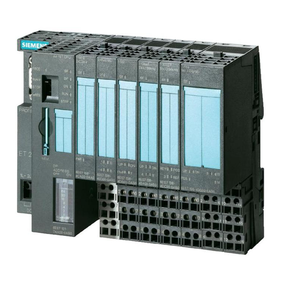
Page 27: View Of The Et 200S Distributed I/O System
Product Overview View The figure below shows an example of an ET 200S configuration. Electronic modules ET 200S interface module Power module for PM-D motor starters Terminating module PM-E power module for electronic modules Direct-on-line starter Reversing starter TM-E terminal modules for electronic modules TM-P terminal modules for... - Page 28 Product Overview Components of the ET 200S The following table provides you with an overview of the most important components of the ET 200S: Table 1-1 Components of the ET 200S Component Function Drawing DIN rail ...carries the ET 200S. You mount the ET 200S on the rail.
-
Page 29: Components Of The Et 200S
Product Overview Table 1-1 Components of the ET 200S Component Function Drawing Terminal module ...carries the wiring and receives the power and electronic modules. Terminal modules are available in the following variants: • For power modules • For electronic modules •... - Page 30 Product Overview Table 1-1 Components of the ET 200S Component Function Drawing Shield contact ...for connecting cable shields. Labeling sheet ...for machine labeling or printing (DIN A4, perforated, • 80 strips per labeling sheet foil) Slot number labels ...for identifying the slots on the terminal module.
-
Page 31: Features And Benefits Of The Et 200S
Product Overview Table 1-2 Features and benefits of the ET 200S Features Benefits Communication-capable, system-integrated PLC inputs and outputs, terminal blocks, motor starters: direct-on-line starters and circuit breakers and contactors in a plug-in reversing starters up to 7.5 kW module save space and the effort involved in wiring Permanent wiring due to the separation of •... - Page 32 Product Overview Guide to the ET 200S manuals You are using the following components ... The components of ET 200S are described in various manuals. These manuals make up the manual package for ET 200S. The figure below shows possible ET 200S configurations and the manuals required for them.
-
Page 33: Components And The Manuals Required For Them
Product Overview You will require the information The ET 200S consists of the follo- contained in the following manuals: wing components: IM 151 ET 200S Distributed I/O System ET 200S Motor Starters ET 200S Safety-Integrated SIGUARD System ET 200S Distributed I/O System ET 200S Distributed I/O System, Fail- Safe Modules manual in the documentation packages:... -
Page 34: Topics Of The Manuals In The Et 200S Manual Package
Product Overview Where do you find what information? The table below will help you get your bearings and find the information you need quickly. It tells you which manual you need to refer to and which chapter deals with the topic you are interested in. Table 1-3 Topics of the manuals in the ET 200S manual package Manual... - Page 35 Product Overview Table 1-3 Topics of the manuals in the ET 200S manual package Manual ET 200S ET 200S ET 200S ET 200S IM151-7 ET 200S Description Distrib- Pro- Posi- Serial CPU In- Motor Chap- uted I/O cess- tioning Inter- terface Starter ter/Ap-...
- Page 36 Product Overview Table 1-3 Topics of the manuals in the ET 200S manual package Manual ET 200S ET 200S ET 200S ET 200S IM151-7 ET 200S Description Distrib- Pro- Posi- Serial CPU In- Motor Chap- uted I/O cess- tioning Inter- terface Starter ter/Ap-...
- Page 37 Brief Instructions on Commissioning ET 200S Introduction The following simple example teaches you step by step how to commission the ET 200S: • Installing and wiring the ET 200S • Configuration with STEP 7 using the device database file • Integration in the user program •...
-
Page 38: Components For The Example
Brief Instructions on Commissioning ET 200S The following figure illustrates the ET 200S components you require for the example: Slot IM151-1 Rail Terminating module 4 x TM-E15S24-A1 terminal module and 2DO 24 VDC/0.5 A High Feature electro- nic module TM-P15S23-A1 terminal module and PM-E 24 VDC power module 4 x TM-E15S24-A1 terminal module and 2DI 24 VDC High Feature electronic module... - Page 39 Brief Instructions on Commissioning ET 200S Requirements • You must have set up an S7 station consisting of a power supply module and a DP master (for example, CPU 315-2 DP). A CPU 315-2 DP was used as the DP master in this example. However, any other DP master (IEC 61784-1:2002 Ed1 CP 3/1) could be used instead.
-
Page 40: Wiring Of The Example
Brief Instructions on Commissioning ET 200S Wiring and fitting 1. Wire the ET 200S as shown below: AUX1 AUX1 24 VDC 24 VDC 24 VDC Sensor supply po- Load supply poten- Electronic tential group 1 tial group 2 supply Figure 2-3 Wiring of the example 2. - Page 41 Brief Instructions on Commissioning ET 200S Configuration 1. Start SIMATIC Manager, and create a new project with a DP master (CPU315-2 DP, for example). Create OB1 and OB82 for the project. 2. Create the PROFIBUS subnet. 3. Connect the PROFIBUS subnet with the DP master in HW Config. 4.
- Page 42 Brief Instructions on Commissioning ET 200S Integration in the user program 1. Create the user program in the LAD/STL/FBD editor in OB1. Example 1: Reading an input and driving an output: A I 0.0 If input bit 0.0 and A M 2.0 memory bit 2.0 are set, then S Q 0.0 set output bit 0.0...
- Page 43 Brief Instructions on Commissioning ET 200S Removing and inserting the 2 DI 24 VDC High Feature digital electronic module 1. Remove the 2 DI 24 VDC High Feature electronic module from the terminal module during operation. 2. Watch the status LEDs on the IM 151-1 STANDARD: –...
- Page 44 Brief Instructions on Commissioning ET 200S Switching off the load voltage on the power module 1. Switch off the load voltage on the PM-E 24 VDC (slot 1). 2. Watch the status LEDs. IM 151 STANDARD: – SF: Lights up Power module: –...
- Page 45 Brief Instructions on Commissioning ET 200S Wire break in the actuator wiring 1. Remove the cable from terminal 1 on the 2 DO 24 VDC/0.5 A; High Feature electronic module (slot 7) 2. Watch the status LEDs. IM151-1 STANDARD: – SF: Lights up 2DO 24 VDC/0.5 A High Feature electronic module: –...
- Page 46 Brief Instructions on Commissioning ET 200S ET 200S Distributed I/O System 2-10 EWA-4NEB780602402-09...
- Page 47 Configuration Options Chapter overview Section Description Page Finely-graduated modular system Power supply of the ET 200S Placement and connection to common potential of power modules Configuration options of the interface modules Configuration options between the terminal modules and electronic modules Direct communication 3-25 Clocking...
-
Page 48: Examples Of Et 200S Setups
Configuration Options Finely-graduated modular system In describing the ET 200S as a finely-graduated modular system, we mean you can adapt the ET 200S to meet the exact requirements of your application. The figure below shows you a number of examples of ET 200S distributed I/O system configurations: Table 3-1 Examples of ET 200S setups... - Page 49 Configuration Options Table 3-1 Examples of ET 200S setups Example Setup ET 200S with Slot • Electronic modules • Motor starter Mandatory ET 200S Distributed I/O System EWA-4NEB780602402-09...
-
Page 50: Power Supply Of The Et 200S
Configuration Options Power supply of the ET 200S The following alternative power supplies are available to you for the ET 200S: • 24 VDC supply on the interface module • 240/400 VAC supply via ET 200S Power Supply See Table 3-2. Table 3-2 Power supply of the ET 200S Power supply... -
Page 51: Placement And Connection To Common Potential Of Power Modules
Configuration Options Placement and connection to common potential of power modules Placement and connection to common potential You can choose where to position the power modules in the ET 200S. Each TM-P terminal module (for a power module) that you install in the ET 200S opens a new potential group. - Page 52 Configuration Options Warning If you connect the AUX1 bus to common potential independently of the P1/P2 buses (different voltages), there is no safe electrical isolation between the AUX1 bus and the P1/P2 buses. Connecting different potentials to the AUX1 bus Note If you apply different potentials to the AUX1 bus in an ET 200S station, you must isolate the potential groups by means of a power module with the terminal module...
-
Page 53: Interface Modules And The Applications For Which They Are Suited
Configuration Options Configuration options of the interface modules The interface module to suit your application: Table 3-3 Interface modules and the applications for which they are suited Applications Interface module • Connecting the PROFIBUS-DP by means of the Transmission rates: IM151-1 BASIC RS 485 interface 9.6, 19.2, 45.45, 93.75,... -
Page 54: Fiber-Optic Cable Network With Im151-1 Fo Standard
Configuration Options Rules for setting up a fiber-optic cable network with the IM 151-1 FO STANDARD For a fiber-optic cable network with nodes that have integrated fiber-optic cable interfaces, note the following: • The fiber-optic cable network can be set up only as a line segment. •... -
Page 55: Electronic Modules And The Applications For Which They Are Suitable
Configuration Options Configuration options between the terminal modules and electronic modules The electronic modules to suit your application: Table 3-4 Electronic modules and the applications for which they are suitable Applications Electronic module • Evaluating switches, 24 VDC 2DI 24 VDC Standard proximity switches 2DI 24 VDC High Feature (BEROs), sensors, and... - Page 56 Configuration Options Table 3-4 Electronic modules and the applications for which they are suitable, continued Applications Electronic module • Measuring currents with "20 mA/ 4 to 20 mA 2AI I 4WIRE Standard four-wire measuring transducers • Measuring currents with "20 mA/ 4 to 20 mA 2AI I 2/4WIRE High Feature two-wire, four-wire measuring transducers and...
- Page 57 Configuration Options Table 3-4 Electronic modules and the applications for which they are suitable, continued Applications Electronic module • Detection and evaluation of Absolute position encoder: 1SSI path positions by means of 13 bits/21 bits/25 bits absolute position encoders absolute position encoders (SSI) •...
-
Page 58: Assignment Of Tm-P Terminal Modules And Power Modules
Configuration Options The electronic modules you can use on the various terminal modules: You can combine the terminal modules in the ET 200S configuration. Table 3-5 Assignment of TM-P terminal modules and power modules Power modules TM-P terminal modules for power modules Screw-type term. - Page 59 Configuration Options Table 3-6 Assignment of TM-E terminal modules and electronic modules, continued Electronic modules TM-E terminal modules for electronic modules Screw-type term. Screw-type term. 15S26-A1 15S24-A1 15S24-01 15S23-01 15S24-AT 30S44-01 30S46-A1 Order number Order number ...4CA40- ...4CA20- ...4CB20- ...4CB00- ...4CL20- ...4CG20- ...4CF40-...
- Page 60 Configuration Options Table 3-6 Assignment of TM-E terminal modules and electronic modules, continued Electronic modules TM-E terminal modules for electronic modules Screw-type term. Screw-type term. 15S26-A1 15S24-A1 15S24-01 15S23-01 15S24-AT 30S44-01 30S46-A1 Order number Order number ...4CA40- ...4CA20- ...4CB20- ...4CB00- ...4CL20- ...4CG20- ...4CF40-...
- Page 61 Configuration Options The power modules you can use with the various electronic modules: Power modules Electronic modules PM-E 24 VDC Can be used with all electronic modules except the 2DI 120 VAC Standard, 2DI 230 VAC Standard, and 2DO 120/230 VAC. PM-E 24–48 VDC Can be used with all electronic modules except the 2DI 120 VAC Standard, 2DI 230 VAC Standard, and 2DO 120/230 VAC.
- Page 62 Configuration Options How to find the right terminal module for a power module for your application: Screw-type terminal: Do you TM-P15S22-01 need access at this (2x2 terminals) terminal module to the AUX1 Spring terminal: bus by means of terminals (for exam- TM-P15C22-01 ple, for protective conductors or addi- (2x2 terminals)
- Page 63 Configuration Options Configuration examples: terminal modules for power modules Table 3-7 Terminal modules for power modules Terminal Setup module TM-P15S22-01 Potential group 2 Potential group 1 Backplane TM-P15C22-01 bus P1 TM-P15N22-01 PM EM EM EM PM EM EM EM EM EM AUX1 TM-P15S23-A1 Potential group 1...
-
Page 64: Terminal Modules For Power Modules
Configuration Options Table 3-7 Terminal modules for power modules, continued Terminal Setup module TM-P15S23-A0 Potential group 1 Potential group 2 TM-P15C23-A0 Backplane bus TM-P15N23-A0 PM EM EM EM PM EM EM EM EM EM AUX1 Access by means of termi- Open new potential group by means of AUX1 nals to AUX1 TM-P30S44-A0... - Page 65 Configuration Options Table 3-7 Terminal modules for power modules, continued Terminal Setup module TM-PF30S47-F1 Potential group 1 Potential group 2 Backplane bus AUX1 ET 200S Distributed I/O System 3-19 EWA-4NEB780602402-09...
- Page 66 Configuration Options How to find the right terminal module for an electronic module for your application: Screw-type terminal: TM-E15S26-A1 (2x6 terminals) Do you need a terminal module that Spring terminal: is suitable for all electronic modules TM-E15C26-A1 (2x6 terminals) (width 15 mm) and that provides access to the AUX1 bus via terminals? Fast Connect: TM-E15N26-A1 (2x6 terminals)
- Page 67 Configuration Options Configuration examples: Terminal modules for electronic modules Table 3-8 Terminal modules for electronic modules Terminal modules Setup TM-E15S26-A1 Potential group 1 Potential group 2 TM-E15C26-A1 Backplane TM-E15N26-A1 bus P1 AUX1 Access via terminals to AUX 1 TM-E15S24-A1 Potential group 1 Potential group 2 TM-E15C24-A1 Backplane bus...
-
Page 68: Terminal Modules For Electronic Modules
Configuration Options Table 3-8 Terminal modules for electronic modules, continued Terminal modules Setup TM-E15S24-01 Potential group 1 Potential group 2 TM-E15C24-01 Backplane TM-E15N24-01 bus P1 AUX1 TM-E15S23-01 TM-E15C23-01 Potential group 1 Potential group 2 Backplane bus TM-E15N23-01 EM PM AUX1 ET 200S Distributed I/O System 3-22 EWA-4NEB780602402-09... - Page 69 Configuration Options Table 3-8 Terminal modules for electronic modules, continued Terminal modules Setup TM-E15S24-AT Potential group 1 Potential group 2 TM-E15C24-AT Backplane bus P1 AUX1 TM-E30S44-01 TM-E30C44-01 Potential group 1 Potential group 2 Backplane bus P1 AUX1 ET 200S Distributed I/O System 3-23 EWA-4NEB780602402-09...
- Page 70 Configuration Options Table 3-8 Terminal modules for electronic modules, continued Terminal modules Setup TM-E30S46-A1 TM-E30C46-A1 Potential group 1 Potential group 2 Backplane bus P1 AUX1 ET 200S Distributed I/O System 3-24 EWA-4NEB780602402-09...
-
Page 71: Direct Communication With The Im151-1 High Feature
Configuration Options Direct communication Requirements • The ET 200S can be used as the sender (publisher) for direct communication. • The DP master being used must, of course, also support direct communication. You will find information on this in the description of the DP master. Principle Direct communication is characterized by the fact that PROFIBUS-DP nodes monitor the data sent back by a DP slave to its DP master. -
Page 72: 1Ssi
Configuration Options Clocking Features Reproducible response times (i.e. of equal length) are achieved in SIMATIC with an equidistant DP bus cycle, synchronization of the user program on the DP bus cycle, and the clocked transfer of I/O data to the I/O modules. The clocked sections of the user program are processed synchronously to the DP bus cycle by means of clocked interrupts (OB 61 to OB 64). - Page 73 Configuration Options • The transmission rate of the PROFIBUS-DP is at least 1.5 Mbps (shorter equidistance times can be achieved with higher transmission rates). • The maximum equidistance is 32 ms. • The equidistance master (class 1) must be a class 1 DP master. In other words, a programming device (PG)/PC cannot be an equidistance master.
-
Page 74: Clocked Interrupts Dialog Box
Configuration Options Procedure for parameterizing clocking 1. Carry out settings on the CPU: “Object Properties” of the CPU > “Clocked interrupts” tab – Set the CPU clocked interrupt – Select the DP master system used. – Select the desired partial process image. Time-of-day Protection Memory... -
Page 75: Options Dialog Box
Configuration Options Constant bus Network stations Cables cycle time Activate equidistant bus cycle Optimize DP cycle (and Ti, To, if required): Recalculate Number of PGs/OPs/TDs etc. on the PROFIBUS Configured: Total: Time base: 8.000 0.125 Details ... Constant DP cycle: (min = 6.000 ms;... -
Page 76: Dp Slave Properties Dialog Box
Configuration Options 3. Carry out settings on the DP slave: “Object Properties” of the DP slave > “Clocking” tab – Enable “Synchronize DP slave with DP cycle”. – Enter the times Ti and To (if “Times Ti and To same for all slaves” has not been set on the DP master system). - Page 77 Configuration Options 4. Create a user program: – Create OB 61. – At the beginning of OB 61, SFC 126 must be called to upgrade the partial process image of the inputs. – At the end of OB 61, SFC 127 must be called to upgrade the partial process image of the outputs.
- Page 78 Configuration Options Option handling Features Option handling enables you to set up the ET 200S for future expansions (options). Option handling means that you install, wire, configure, and program the planned maximum configuration of the ET 200S. The electronic modules you require for this are initially replaced with inexpensive RESERVE modules which are then later simply exchanged for the required electronic modules.
-
Page 79: How Option Handling Works
Configuration Options How it works At option handling, the configuration of slots 2 to 63 of the ET 200S is checked. If the check is enabled for a slot, the RESERVE module (option) or the configured electronic module can take up this slot without a diagnosis being reported. If the check is disabled, only a configured electronic module can be located in this slot. - Page 80 Configuration Options Prerequisites For option handling you require: • IM 151-1 STANDARD (6ES7151-1AA03-0AB0) or IM 151-1 FO STANDARD interface module (6ES7151-1AB02-0AB0) • To configure the DDB file: – IM 151-1 STANDARD: SI02806A.GSx as of 07/2003 (as of V1.0) – IM 151-1 FO STANDARD: SI02806B.GSx as of 07/2003 (as of V1.0) Note You do not require a DDB file for option handling in STEP 7: as of STEP 7 V5.2 Service Pack 1 and...
-
Page 81: Example Of The Use Of The Reserve Modules
Configuration Options Example of the use of RESERVE modules This setup Future must be confi- planned gured maximum (HWCONFIG, configura- COM PROFI- tion of the BUS) ET 200S Basic Basic config. Option 1 Option 2 config. 1st version: You must install Preparation and wire this using... - Page 82 Configuration Options Option handling parameter assignment Note the following prerequisites when assigning parameters: • In STEP 7 or COM PROFIBUS, parameterize the electronic modules you want to use for future applications, such as 4DI HF, on the slots of the RESERVE modules (or the expansion modules at the right-hand end of the station): –...
- Page 83 Configuration Options • Parameterize the interface module as follows: Interface module Parameters Setting Description IM 151-1 Option Enable Option handling is activated STANDARD handling, for the whole ET 200S. general Option Enable (all the There are RESERVE IM 151-1 FO handling: slots slots on which modules or configured...
-
Page 84: Control (Piq) And Feedback Interface (Pii)
Configuration Options Controlling and monitoring options You can use the control feedback interface (PIQ) and feedback interface (PII) to control and monitor the options with the user program. Recommended: Before you use the optional expansion of the ET 200S, check using the feedback interface (see Table 3-10) whether all the configured electronic modules are inserted. -
Page 85: Troubleshooting For Option Handling
Configuration Options Table 3-9 Control interface Slot Value of the Response 2 to 63 Parameter assignment for option handling applies. RESERVE modules are permitted: • The station is transferring data. • A diagnosis is not reported. • The SF LED on the interface module is off. Parameter assignment for option handling is cancelled. -
Page 86: Parameter Length In Bytes
Configuration Options Limitations on the number of modules that can be connected/maximum configuration • Number of modules: – ET 200S with IM151-1 BASIC: max. 12 modules – ET 200S with IM151-1 STANDARD; IM151-1 FO STANDARD; IM151-1 HIGH FEATURE: max. 63 modules This includes power modules, electronic modules, RESERVE modules, and motor starters. - Page 87 Configuration Options Table 3-12 Parameter length in bytes, continued Module Parameter Module Parameter length length 2DO 24 VDC/0.5 A; Standard 1 byte 1SSI 8 bytes 4DO 24 VDC/0.5 A Standard 2DO 24 VDC/2 A High Feature 3 bytes 1STEP 5 V/204 kHz 7 bytes 2DO 24 VDC/2 A Standard 1 byte...
-
Page 88: Maximum Configuration Per Potential Group
Configuration Options • Power modules: Maximum configuration per potential group Table 3-13 Maximum configuration per potential group Power modules Maximum Connectable modules current-carrying capacity Power module 10 A The number of modules that can be PM-E 24 VDC connected depends on the total current of all the modules in this potential group. -
Page 89: Setting The Profibus Address
Installation Simple installation The ET 200S distributed I/O system is designed for simple installation. Chapter overview Section Description Page Installation rules, installation position, rail, installation measurements and clearances Installing the interface module Installing the TM-P and TM-E terminal modules Replacing the terminal box on the terminal module Installing the terminating module 4-10 Installing the shield contact... - Page 90 Installation Installation rules, installation position, rail, installation measurements and clearances Installation rules • The ET 200S distributed I/O system starts with an interface module. • There is a power module after the interface module or at the beginning of each potential group.
- Page 91 Installation Installation measurements Table 4-1 Installation measurements Mea- sure- ments • Installa- Interface module: 45 mm tion • Terminal modules with electronic modules: 15 mm or 30 mm width • Terminating module: 7.5 mm • Installa- Interface module: 119.5 mm tion •...
-
Page 92: Installing The Interface Module
Installation Minimum clearances for installation, wiring, and ventilation When installing the ET 200S in a housing, ensure that the distance to the lid of the housing or the front door is at least 2 mm. 35 mm EM EM PM EM EM 20 mm 20 mm... -
Page 93: Installing The Interface Module
Installation Tool required 3-mm screwdriver Installing the interface module 1. Hang the interface module on the rail. 2. Tip the interface module back until you hear the locking mechanism engage. Figure 4-2 Installing the interface module Removing the interface module The interface module is wired, and the terminal modules are on the right: 1. -
Page 94: Installing The Terminal Module
Installation Installing the TM-P and TM-E terminal modules Features • The terminal modules receive the I/O modules and power modules. • The terminal modules can be prewired (without I/O modules). • All the terminal modules must be installed to the right of the interface module. Requirements •... -
Page 95: Removing The Terminal Module (From The Right)
Installation Removing the terminal module The terminal module is wired, and there are other terminal modules on the right and left. A terminal module in the ET 200S distributed I/O system can only be removed when there is a clearance of around 8 mm to the adjacent terminal modules (you achieve this clearance by moving the adjacent modules). -
Page 96: Replacing The Terminal Box On The Terminal Module
Installation Replacing the terminal box on the terminal module Features The terminal box is part of the terminal module. If necessary, you can replace the terminal box. Requirements It is not necessary to remove the terminal module. Tool required 3-mm screwdriver ET 200S Distributed I/O System EWA-4NEB780602402-09... -
Page 97: Replacing The Terminal Box On The Terminal Module
Installation Replacing the terminal box on the terminal module The terminal module is installed, wired, and fitted with an electronic module. 1. Switch off the supply voltage on the terminal module and, if applicable, the power module. 2. Disconnect the wiring on the terminal module. 3. -
Page 98: Installing The Terminating Module
Installation Installing the terminating module Features The ET 200S distributed I/O system is completed by the terminating module on the right-hand side. If you have not connected a terminating module, the ET 200S is not ready for operation. Requirements • The last terminal module must be installed. Installing the terminating module 1. -
Page 99: Installing The Shield Contact
Installation Installing the shield contact Features • You need the shield contact to connect cable shields (for example, analog electronic modules, 1Count 24V/100kHz electronic module and 1SSI electronic module). • You fit the shield contact on the terminal module. • The shield contact consists of a shield contact element, a conductor rail, (3 x 10 mm), a shield terminal, and a ground connection terminal. -
Page 100: Installing The Shield Contact
Installation Installing the shield contact 1. Push the shield contact element onto the first terminal module from below. 2. Push the shield contact element onto the last terminal module from below. In order to achieve stability of the conductor rail between two shield contact elements during installation, you must connect an additional shield contact element after every sixth terminal module (given a width of 15 mm). -
Page 101: Applying Slot Number Labels And Color Identification Labels
Installation Applying slot number labels and color identification labels Features • The slot number labels identify the individual I/O modules with a slot (1 to 63). • The color identification labels permit individual color coding of the terminals in accordance with company or national conventions. The color identification labels are available in white, red, blue, brown, yellow, yellow-green, and turquoise. -
Page 102: Applying Slot Number Labels And Color Identification Labels
Installation Applying slot number labels and color identification labels Slot number labels: 1. Break the slot number label (1 to 63) off the strip. 2. Use your finger to press the slot number label onto the terminal module. Color identification labels: 1. -
Page 103: Setting The Profibus Address
Installation Setting the PROFIBUS address Features The PROFIBUS address defines the address at which the ET 200S distributed I/O system is found on the PROFIBUS-DP. Requirements • The PROFIBUS-DP address for the ET 200S is set on the interface module by means of DIP switches. - Page 104 Installation Changing the PROFIBUS-DP address You change the PROFIBUS-DP address in exactly the same way as you set it. A change to the PROFIBUS-DP address takes effect after power on at the interface module of the ET 200S. ET 200S Distributed I/O System 4-16 EWA-4NEB780602402-09...
- Page 105 Wiring and Fitting Prewiring The ET 200S distributed I/O system allows you to prewire the terminal modules with screw-type or spring terminals. Chapter overview Section Description Page General rules and regulations for operating the ET 200S Operating the ET 200S on a grounded supply Electrical design of the ET 200S Wiring the ET 200S Inserting and identifying the electronic modules...
- Page 106 Wiring and Fitting General rules and regulations for operating the ET 200S Introduction When operating the ET 200S distributed I/O system as a component part of a plant or system, certain rules and regulations have to be followed depending on where the device is to be used.
- Page 107 Wiring and Fitting Line voltage The following table tells you what you have to do with regard to the line voltage. With ... Requirements Permanently installed plants or systems There must be a line disconnect switch or a without all-pole line disconnect switches fuse in the building installation system.
- Page 108 Wiring and Fitting Operating the ET 200S on a grounded supply In this section, you will find information on the overall setup of an ET 200S distributed I/O system on a grounded supply (TN-S system). The specific subjects discussed are: •...
- Page 109 Wiring and Fitting Setting up the ET 200S with ungrounded reference potential As of the IM151-1 BASIC (6ES7151-1CA00-0AB0), IM151-1 STANDARD (6ES7151-1AA02-0AB0), IM151-1 FO STANDARD (6ES7 151-1AB01-0AB0) and IM151-1 HIGH FEATURE (6ES7151-1BA00-0AB0), the reference potential M of the rated supply voltage for the IM151-1 is connected to the rail (protective conductor) by means of an RC combination, therefore making an ungrounded configuration possible.
-
Page 110: Configuring The Et 200S With Grounded Reference Potential
Wiring and Fitting Overall configuration of the ET 200S Figure 5-1 shows the overall configuration of the ET 200S distributed I/O system (load voltage supply and grounding concept) with supply from a TN-S system. Low-voltage distribution – TN-S system, for example (3 400 V) FG: Functional ground to divert noise di- rectly to the DIN rail by means of a spring... -
Page 111: Operating The Et 200S With Grounded Reference Potential
Wiring and Fitting Figure 5-2 shows the overall setup of the ET 200S distributed I/O system (load power supply and grounding concept) with the ET 200S Power Supply and an incoming supply from a TN-S system. Low-voltage distribution – TN-S system, for example (3 400 V) FG: Functional ground to divert noise... -
Page 112: Potentials Of The Et 200S
Wiring and Fitting Electrical design of the ET 200S Isolation between ... • The load circuits/process and all other circuit components of the ET 200S • The PROFIBUS-DP interface in the interface module and all other circuit components The following figure shows the potentials of the ET 200S. Only the most important components are shown. - Page 113 Wiring and Fitting Wiring the ET 200S Section Description Page 5.4.1 Wiring a terminal module with screw-type terminals 5-10 5.4.2 Wiring a terminal module with spring terminals 5-10 5.4.3 Wiring a terminal module with Fast Connect 5-12 5.4.4 Wiring terminal modules 5-15 5.4.5 Wiring the IM151-1 BASIC, IM151-1 STANDARD and IM151-1...
- Page 114 Wiring and Fitting 5.4.1 Wiring a terminal module with screw-type terminals Features • In terminal modules with screw-type terminals, the individual wires are screwed into the terminal. • No wire end ferrules are required. Requirements Adhere to the wiring rules. Tool required 3-mm screwdriver Wiring a terminal module with a screw-type terminal...
-
Page 115: Wiring The Spring Terminal
Wiring and Fitting Wiring a terminal module with spring terminals 1. Strip 11 mm of insulation from the wires. 2. Insert the screwdriver in the upper (round) opening of the terminal. 3. Insert the wire until it stops in the lower (square) opening of the terminal. 4. -
Page 116: Block Diagram Of The Terminal Module With Fast Connect
Wiring and Fitting 5.4.3 Wiring terminal modules with Fast Connect Features • In the case of terminal modules with Fast Connect, the individual wires are attached using a quick connection method that requires no stripping. • Fast Connect is a connection method that requires no preparation (i.e. the conductor does not have to be stripped). - Page 117 Wiring and Fitting Connectable cables You can connect rigid and flexible cables with PVC insulation with a conductor cross-section of 0.5 mm to 1.5 mm (max. external diameter 3.2 mm). If the cross-section of the conductors is the same, they can be wired fifty times. You can find a list of tested conductors at: http://www.idc2.de Cables and connections complying with UL...
-
Page 118: Releasing The Wiring Of The Terminal Module With Fast Connect
Wiring and Fitting Releasing the wiring of the terminal module with Fast Connect 1. Insert the screw driver into the opening under the locking mechanism until it stops. 2. Use the screwdriver to lever and push the locking mechanism upwards. 3. - Page 119 Wiring and Fitting 5.4.4 Wiring terminal modules Features The ET 200S distributed I/O system comprises terminal modules for power modules and electronic modules: • At the terminal modules for the power modules you connect the supply/load voltage for the respective potential group. •...
-
Page 120: Wiring Terminal Modules For Power Modules
Wiring and Fitting Wiring terminal modules for power modules The terminal assignment of the terminal module depends on which power module is inserted. You will find information on this in the following chapters: • Terminal modules in Chapter 10 • Power modules in Chapter 11 TM-P15S23-A1 and TM-P15S22-01 and TM-P15S23-A0 and... -
Page 121: Wiring Terminal Modules For Electronic Modules
Wiring and Fitting Wiring terminal modules for digital, analog, and technology modules The terminal assignment of the terminal module depends on which electronic module is inserted. You will find information on this in the following chapters: • Terminal modules in Chapter 10 •... -
Page 122: Wiring Terminal Modules For Electronic Modules, Continued
Wiring and Fitting TM-E30S46-A1 and fail-safe TM-E30S44-01 and the module* process-related module F-DO F-DO Channel 1 Channel 0 FD-I FD-I AUX1 bus (PE) fed through. No connection to terminals 4 and 8 or 12 and 16. AUX1 bus (PE) fed through. Connection to termi- nals A4, A8 and A3, A7 or A12, A16 and A11 and A15. -
Page 123: Connecting Cable Shields
Wiring and Fitting Connecting cable shields We recommend you use the shield contact to connect cable shields (in the case of analog electronic modules, the 1Count 24V/100kHz electronic module and the 1SSI electronic module, for example). 1. Remove the insulation material from the area around the shield terminal, and clamp the cable shield in the shield terminal (above the conductor rail). -
Page 124: Wiring The Im151-1 Basic, Im151-1 Standard
Wiring and Fitting 5.4.5 Wiring the IM151-1 BASIC, IM151-1 STANDARD and IM151-1 HIGH FEATURE interface modules Features You can connect the supply voltage and the bus connector (RS 485) to the interface modules IM151-1 BASIC, IM151-1 STANDARD and IM151-1 HIGH FEATURE. - Page 125 Wiring and Fitting 5.4.6 Wiring the IM151-1 FO STANDARD interface module Features Connect the supply voltage and the fiber-optic cable to the IM151-1 FO STANDARD interface module by means of a simplex connector. Requirements • Wire the interface module with the supply voltage switched off. •...
- Page 126 Wiring and Fitting Installing simplex connectors 1. Remove about 30 cm of the cladding of the fiber-optic duplex cable. 2. Install the fiber-optic duplex cable with the appropriate simplex connectors. For detailed instructions on installing the simplex connectors, see the SIMATIC NET PROFIBUS networks manual.
- Page 127 Wiring and Fitting Using the fiber-optic cable again Note If you place used fiber-optic cable in the connector adapter, you must shorten both cores of the fiber-optic cable by the bent lengths and remount the simplex connectors. In this manner you avoid possible attenuation losses from parts of the fiber-optic cable duplex core that have been bent again and highly stressed Wiring the IM151-1 FO STANDARD interface module To connect the supply voltage:...
-
Page 128: Wiring The Im151-1 Fo Standard
Wiring and Fitting Caution Do not look directly into the opening of the transmission diodes. The light beam that comes out could damage your eyes. Handle Transmitter PROFIBUS-DP (fiber-optic cable) Receiver Labeling strip Simplex connector ET 200S Supply voltage (1L+, 2L+, 1M, 2M) Figure 5-13 Wiring the IM151-1 FO STANDARD Inserting and identifying the electronic modules... -
Page 129: Inserting And Identifying Electronic Modules
Wiring and Fitting Inserting and identifying the electronic modules 1. Insert the electronic module in the terminal module until you hear it snap into place. 2. Pull the labeling strip up out of the electronic module in order to identify it. 3. -
Page 130: Removing Electronic Modules
Wiring and Fitting Removing electronic modules 1. Simultaneously press the two release buttons on the top and bottom of the electronic module. 2. Pull the electronic module out from the terminal module at the front. Figure 5-15 Removing electronic modules ET 200S Distributed I/O System 5-26 EWA-4NEB780602402-09... -
Page 131: Removing The Code Element
Wiring and Fitting Changing the type of an electronic module You have already removed the electronic module: 1. Use a screwdriver to push the code element out of the terminal module. 2. Put the code element on the used electronic module again. 3. - Page 132 Wiring and Fitting Removing and inserting electronic modules during operation ET 200S supports the removal and insertion of modules during operation (during the RUN operating mode). The ET 200S remains in RUN mode when an electronic module is removed. The protective conductor connections of the ET 200S are not interrupted.
- Page 133 Wiring and Fitting Table 5-1 Removing and inserting electronic modules Modules Removing and Conditions inserting 1Count 24V/100kHz The load voltage must be switched off by means of an it h d ff b 1Count 5V/500kHz external switch/fuse. external switch/fuse. 1SSI 1STEP 5V/204kHz 2PULSE 1POS INC/Digital...
- Page 134 Wiring and Fitting ET 200S Distributed I/O System 5-30 EWA-4NEB780602402-09...
- Page 135 Commissioning and Diagnostics Chapter overview Section Description Page Configuring the ET 200S Commissioning and startup of the ET 200S 6-10 Diagnostics using LEDs 6-12 Diagnostic messages of the electronic modules 6-23 Evaluating the interrupts of the ET 200S 6-24 Diagnostics using STEP 5 and STEP 7 6-26 ET 200S Distributed I/O System EWA-4NEB780602402-09...
- Page 136 Commissioning and Diagnostics Configuring the ET 200S Introduction This chapter describes how to configure and assign parameters to the ET 200S. • Configuration: The systematic arrangement of the different ET 200S modules (setup) • Parameter assignment: Setting the ET 200S parameters using the configuration software Note The ET 200S is included in the hardware catalog of HWCONFIG:...
- Page 137 (*.GSD file). The ET 200S is integrated in your system as a standard slave by means of the device database file. You can download the *.GSD file in either of the following ways: • From the Internet under http://www.ad.siemens.de/csi_e/gsd The following *.GSD files are available: • IM151-1 BASIC: “SIEM80F3.GSx”...
- Page 138 Commissioning and Diagnostics Configuration The ET 200S has maximum address space of: • IM151-1 BASIC: up to 88 bytes for inputs and 88 bytes for outputs • IM151-1 STANDARD, IM151-1 FO STANDARD: up to 128 bytes for inputs and 128 bytes for outputs •...
- Page 139 Commissioning and Diagnostics Note In STEP 7 applications, if you group the modules in the IM151-1 HIGH FEATURE in DPV1 mode, the following occurs: No removal/insertion interrupts (OB 83) are triggered for these modules. In this • case, you can recognize a module that has been removed from the module status in the diagnostic frame in the cyclic user program.
-
Page 140: Grouping Of Input Modules In A Single Byte
Commissioning and Diagnostics Grouping of digital input modules IM151-1 STANDARD, 6ES7151-1AA00-0AB0 with product level 1 to 4 1st Step 2nd Step 3rd Step 2DI 4DI Setup: Without “*” Without “*” Without “*” Designation: With “*” With “*” Input byte: As of IM151-1 BASIC; IM151-1 STANDARD, 6ES7151-1AA00-0AB0 with product level 5, 6ES7151-1AA01-0AB0, IM151-1 FO STANDARD and IM151-1 HIGH FEATURE 1st Step 2nd Step... -
Page 141: Grouping Of Digital Output Modules In A Single Byte
Commissioning and Diagnostics Grouping of digital output modules IM151-1 STANDARD, 6ES7151-1AA00-0AB0 with product level 1 to 4 1st Step 2nd Step 3rd Step Setup: Without “*” Without “*” Without “*” Without “*” Without “*” Designation: With “*” With “*” Output byte: As of IM151-1 BASIC;... -
Page 142: Grouping Of Motor Starters Within A Byte
Commissioning and Diagnostics Grouping of motor starters 1st Step 2nd Step MS MS Setup: Without “*” Without “*” Designation: With “*” Input byte: Output byte: Figure 6-3 Grouping of motor starters within a byte Configuration example The following example describes how to configure an ET 200S setup: Setup of the ET 200S Slot 3 4 5... - Page 143 Commissioning and Diagnostics Configuration table in your configuration software and address space The byte addresses of the inputs and outputs can be freely selected (if the configuration software supports this). The bit addresses result automatically from the sequence of the grouped modules. Table 6-2 Configuration table and address space Slot...
-
Page 144: Software Requirements For Commissioning
Commissioning and Diagnostics Commissioning and startup of the ET 200S Software requirements Table 6-3 Software requirements for commissioning Configuration Version Notes software used STEP 7 As of Version 5.0 You are using HW Config. As of ServicePack 3, the and ServicePack 3 ET 200S is included in the hardware catalog. -
Page 145: Startup Of The Et 200S
Commissioning and Diagnostics Startup of the ET 200S “Startup when expected < > actual confi- Switch on the supply voltage guration” parameter disabled (only in the for the DP slave. case of DPV 0) DP slave sets outputs to “0” and accepts the set PROFI- BUS address. -
Page 146: Leds On The Et 200S Power Supply
Commissioning and Diagnostics Diagnostics using LEDs ET 200S Power Supply Input voltage (green) P24V Output voltage (green) I> Overload (yellow) = On: Output voltage is switched on = Standby: Output voltage is switched off Figure 6-6 LEDs on the ET 200S Power Supply Status and error displays by means of LEDs on the ET 200S Power Supply Table 6-6 Status and error displays of the ET 200S Power Supply... -
Page 147: Led Display On The Interface Module
Commissioning and Diagnostics Interface module Group error (red) Bus fault (red) Supply voltage (green) ET 200S Figure 6-7 LED Display on the interface module Status and error displays using LEDs on the IM151-1 BASIC/IM151-1 STANDARD/IM151-1 FO STANDARD/IM151-1 HIGH FEATURE Table 6-7 Status and error displays of the IM151-1 BASIC/IM151-1 STANDARD/IM151-1 FO STANDARD/IM151-1 HIGH FEATURE SF: red... - Page 148 There is an error in an I/O module, or Replace the interface module, or get in the interface module is defective. touch with your Siemens contact per- son. Data transfer is taking place between – the DP master and the ET 200S.
-
Page 149: Leds On The Power Module
Commissioning and Diagnostics Power modules LEDs Meaning What to do FSG PWR Check the para- No parameter as- Group error meter assign- signment or incor- (red) ment. Evaluate rect module inser- the diagnosis. ted. There is a dia- gnostic message. The fuse in the Replace the fuse. - Page 150 Commissioning and Diagnostics Analog electronic modules Meaning What to do Group error Check the para- No parameter as- (red) meter assign- signment or incor- ment. Check the rect module inser- load voltage. Eva- ted. No load vol- luate the diagno- tage.
- Page 151 Commissioning and Diagnostics 1Count 5V/500kHz Group error (red) Status indicator for the Status indicator digital output (green) counting dir. (green) Status indicator for syn- Status indicator for di- chronization (green) gital input (green) LEDs Meaning What to do DN SYN 9 Check the parameter assign- No parameter assignment.
- Page 152 Commissioning and Diagnostics 1SSI LEDs Meaning What to do No parameter as- Check the parameter Group signment. There is a assignment. Evaluate error (red) diagnostic message. the diagnosis. At value change from smaller to lar- ger sensor values (including zero- crossing) Status indicator At value change...
- Page 153 Commissioning and Diagnostics 2PULSE LEDs Meaning What to do No parameter as- Check the parameter signment. There Group assignment. Evaluate is a diagnostic error (red) the diagnosis. message. Input on channel 0 is activated Input on channel 1 is activated Output on chan- nel 0 is activated Status indicator for...
- Page 154 Commissioning and Diagnostics 1POS INC/Digital, 1POS SSI/Digital, 1POS INC/Analog, 1POS SSI/Analog Group error (red) Status indicators for Status indic. for a digital inputs (green) change in an actual value (green) Positioning in opera- tion (green) LEDs Meaning What to do DN POS 9 Check the parameter assignment.
- Page 155 Commissioning and Diagnostics 1SI 3964/ASCII, 1SI Modbus/USS serial interface modules LEDs Meaning What to do SF TX Hardware fault Check the module Firmware error Parameter assignment Check the parameteriza- Group error tion. Evaluate the diagno- error (red) sis. Check the wiring. Wire break or loose cable between the mo- dule and the communi-...
- Page 156 Commissioning and Diagnostics 4 IQ-SENSE LEDs Meaning What to do Check the parame- No parameter as- Group error ter assignment. signment. (red) Evaluate the dia- There is a diagno- gnosis. stic message. Adjust the reflex Excess gain lower sensor. Clean the limit violated.
- Page 157 Commissioning and Diagnostics Diagnostic messages of the electronic modules Actions after a diagnostic message in DPV0 operation The error is entered in the diagnostic frame in the channel-specific diagnosis: • The SF LED on the interface module comes on. • Several simultaneous diagnostic messages are possible. Actions after a diagnostic message in DPV1 operation Each diagnostic message leads to the following actions: •...
- Page 158 Commissioning and Diagnostics Evaluating the interrupts of the ET 200S Introduction Interrupts are triggered by the DP slave in the event of specific errors occurring. Interrupt evaluation differs depending on the DP master used. Evaluating interrupts with an S7 DP master or DPV1 master The ET 200S supports the following interrupts: •...
- Page 159 Commissioning and Diagnostics Evaluating hardware interrupts with STEP 7 In the event of a hardware interrupt, the CPU interrupts the processing of the user program and processes the process interrupt block OB 40 instead. The module channel that triggered the hardware interrupt is entered in the start information of OB 40 in the OB40_POINT_ADDR variable.
- Page 160 Commissioning and Diagnostics Diagnostics using STEP 5 and STEP 7 Section Description Page 6.6.1 Reading out the diagnosis 6-27 6.6.2 Structure of the slave diagnosis 6-30 6.6.3 Station statuses 1 to 3 6-32 6.6.4 Master PROFIBUS address 6-34 6.6.5 Manufacturer ID 6-34 6.6.6 Module diagnosis...
-
Page 161: Reading The Diagnosis Out Using Step 7 And Step
Commissioning and Diagnostics 6.6.1 Reading out the diagnosis Length of the diagnostic message frame • The maximum message frame length for the ET 200S is as follows: – IM151-1 BASIC: 43 bytes – IM151-1 STANDARD, IM151-1 FO STANDARD, IM151-1 HIGH FEATURE (DPV0 operation): 64 bytes –... - Page 162 Commissioning and Diagnostics Example of reading the slave diagnosis using FB192 “IM308C” Here you will find an example of how to use FB 192 to read out the slave diagnosis for a DP slave in the STEP 5 user program. Assumptions The following assumptions apply to this STEP 5 user program: •...
- Page 163 Commissioning and Diagnostics Example of reading the S7 diagnosis using SFC13 “DP NRM_DG” Here you will find an example of how to use SFC13 to read out the slave diagnosis for a DP slave in the STEP 7 user program. Assumptions The following assumptions apply to this STEP 7 user program: •...
- Page 164 Commissioning and Diagnostics 6.6.2 Structure of the slave diagnosis Structure of the slave diagnosis IM151-1 STANDARD IM151-1 FO STANDARD IM151-1 BASIC IM151-1 HIGH FEATURE Byte 0 Byte 0 Byte 1 Byte 1 Station statuses 1 to 3 Byte 2 Byte 2 Byte 3 Byte 3 Master PROFIBUS address...
- Page 165 Commissioning and Diagnostics Note The length of the diagnostic message frame varies: Between 6 and 43 bytes in the IM151-1 BASIC • Between 6 and 62 bytes in the IM151-1 STANDARD and IM151-1 FO • STANDARD Between 6 and 62 bytes in the case of the IM151-1 HIGH FEATURE in DPV0 •...
-
Page 166: Structure Of Station Status 1 (Byte 0)
Commissioning and Diagnostics 6.6.3 Station statuses 1 to 3 Definition Station statuses 1 to 3 provide an overview of the status of a DP slave. Station status 1 Table 6-9 Structure of station status 1 (Byte 0) Meaning Cause/remedy 1: The DP slave cannot be addressed Correct PROFIBUS address set on the DP •... -
Page 167: Structure Of Station Status 2 (Byte 1)
Commissioning and Diagnostics Station status 2 Table 6-10 Structure of station status 2 (Byte 1) Meaning 1: New parameters have to be assigned to the DP slave. 1: A diagnostic message has been issued. The DP slave will not work until the fault has been corrected (static diagnostic message). -
Page 168: Structure Of The Manufacturer Id (Bytes 4, 5)
Commissioning and Diagnostics 6.6.4 Master PROFIBUS address Definition The master PROFIBUS address diagnostic byte contains the PROFIBUS address of the DP master that: • Assigned parameters to the DP slave and • Has read and write access to the DP slave The master PROFIBUS address is in byte 3 of the slave diagnosis. - Page 169 Commissioning and Diagnostics 6.6.6 Module diagnosis Definition The module diagnosis indicates whether or not modules of the ET 200S have errors/faults. The module diagnosis begins as of byte 6 and comprises: • 3 bytes in the case of the IM151-1 BASIC •...
- Page 170 Commissioning and Diagnostics The module diagnosis for the ET 200S with the IM151-1 STANDARD, IM151-1 FO STANDARD, and IM151-1 HIGH FEATURE is structured as follows: Bit no. Byte 6 Length of the module diagnosis including byte 6 (= 9 bytes) Code for module diagnosis 6 5 4 Bit no.
- Page 171 Commissioning and Diagnostics Module status The module status for the ET 200S with the IM151-1 BASIC is structured as follows: Bit no. Byte 9 Length of the module status including byte 15 (= 7 bytes) Code for module status Byte 10 Status type: Module status Byte 11 Not applicable...
- Page 172 Commissioning and Diagnostics The module status for the ET200S with the IM151-1 STANDARD, IM151-1 FO STANDARD, and IM151-1 HIGH FEATURE is structured as follows: Bit no. Byte 15 Length of the module status including byte 15 (= 20 bytes) Code for module status Byte 16 Status type: Module status Byte 17...
- Page 173 Commissioning and Diagnostics 6.6.8 Channel-specific diagnosis Definition The channel-specific diagnosis gives information on channel errors of modules and expands on the module diagnosis. The channel-specific diagnosis starts after the module status (if the parameters are preset accordingly). The maximum length is limited by the total length of the slave diagnosis from 43/62 bytes in DPV0 mode to 128 bytes in DPV1 mode.
- Page 174 Commissioning and Diagnostics Channel-specific diagnosis The channel-specific diagnosis for the ET 200S with the IM151-1 BASIC is structured as follows: 6 5 4 Bit no. Byte 16 000000 to 001100 : Slot of the module that supplies the channel-specific diagnosis. Code for channel-specific diagnosis 6 5 4 Bit no.
- Page 175 Commissioning and Diagnostics The channel-specific diagnosis for the ET200S with the IM151-1 STANDARD, IM151-1 FO STANDARD, and IM151-1 HIGH FEATURE is structured as follows: 6 5 4 Bit no. Byte 35 000000 to 111111 : Slot of the module that supplies the channel-specific diagnosis.
-
Page 176: Power Module Error Types
Commissioning and Diagnostics Power module error types The diagnostic message is reported on channel 0 and applies to the whole module. Table 6-13 Power module error types Power modules electronic Error type Meaning What to do modules PM-E 24–48 PM-E 10001: Sensor or load No supply voltage, Correct the process... - Page 177 Commissioning and Diagnostics Table 6-14 Digital electronic module error types, continued Digital electronic Error type Meaning What to do modules 4DI 24–48 VUC High 11010: External fault Line to the actuator Correct the process Feature interrupted. wiring. No supply voltage, or Correct the process inadequate supply wiring.
-
Page 178: Analog Input Module Error Types
Commissioning and Diagnostics Analog input module error types Table 6-15 Analog input module error types Analog input modules Error type Meaning What to do 2AI U 2AI U 2AI TC 10000: Module cannot use the Correct the High Standard Standard Parameter parameter for the configuration... -
Page 179: Analog Output Module Error Types
Commissioning and Diagnostics Analog output module error types Table 6-16 Analog output module error types Analog output Error type Meaning What to do modules 2AO U 2AO I 10000: Module cannot use the Correct the configuration Standard Standard Parameter parameter for the channel: (compare actual and assignment desired configuration). -
Page 180: 1Count 24V/100Khz
Commissioning and Diagnostics 1Count 24V/100kHz Table 6-18 1Count 24V/100kHz Error type Meaning What to do 00001: Short circuit Short circuit of the sensor Check the wiring to the sensor. supply or the actuator. Correct the process wiring. 00101: Temperature rise Digital output is overloaded. -
Page 181: 1Pos Inc/Digital, 1Pos Ssi/Digital, 1Pos Inc/Analog
Commissioning and Diagnostics 2PULSE Table 6-21 2PULSE Error type Meaning What to do 00001: Short circuit Short circuit of the sensor Check the wiring to the supply or the actuator. momentary-contact switches and the actuators. Correct the process wiring. 01001: Error Internal module error occurred. -
Page 182: 1Si 3964/Ascii, 1Si Modbus/Uss
Commissioning and Diagnostics 1SI 3964/ASCII, 1SI Modbus/USS serial interface module Table 6-23 1SI 3964/ASCII, 1SI Modbus/USS Error type Meaning What to do 00110: Open circuit Wire broken or disconnected. Check the wiring to the terminals. Check the cable to the partner. 00111: Upper limit violation Buffer overflow;... - Page 183 Commissioning and Diagnostics 4 IQ-SENSE Table 6-24 4 IQ-SENSE Error type Meaning What to do 00001: Short circuit Short circuit of the lines Check the wiring to the sensor. between the electronic module Correct the process wiring. and sensor 00110: Open circuit Line to the actuator interrupted.
- Page 184 Commissioning and Diagnostics 6.6.9 Interrupts Definition The interrupt section of the slave diagnosis provides information on the interrupt type and the cause that led to the triggering of the interrupt. The interrupt section consists of a maximum of 48 bytes. Position in the diagnostic frame The interrupt section comes after the channel-specific diagnosis (only in the case of the IM151-1 HIGH FEATURE in DPV1 operation)
- Page 185 Commissioning and Diagnostics Interrupts The interrupt section for the ET 200S is structured as follows: 5 4 3 2 1 0 0 0 Byte x Length of the interrupt section incl. byte x (= max. 48 bytes) Code for device-specific diagnosis 5 4 3 2 1 Byte x+1 Interrupt type...
- Page 186 Commissioning and Diagnostics Diagnostic interrupt, byte x+4 to x+7 5 4 3 2 1 Incoming diagnosis: 1101 Byte x+4 Outgoing diagnosis: 0000 Module problem (i.e. error detected) Internal error in module External fault: module can no longer be addressed Channel error in module 5 4 3 2 1 Byte x+5 Module class:...
- Page 187 Commissioning and Diagnostics Diagnostic interrupt of the modules 5 4 3 2 1 Byte x+8 Channel type : Input channel : Output channel : Process-related module, motor starter, power module, fail-safe module Byte x+9 Length of the channel-specific diagnosis Byte x+10 Number of channels per module Byte x+11 Diagnostic event on channel 0 of the module...
- Page 188 Commissioning and Diagnostics Example of a diagnostic interrupt Example: The 4DI electronic module reports the “short circuit” diagnostic interrupt on channel 2. 5 4 3 2 1 Byte x 0 1 1 Length of the interrupt section = 27 bytes 5 4 3 2 1 Byte x+1 0 0 1...
- Page 189 Commissioning and Diagnostics 5 4 3 2 1 Byte x+8 0 1 1 Input channel = 7B 5 4 3 2 1 Byte x+9 0 0 0 Length of the channel-specific diagnosis = 32 bits 5 4 3 2 1 Byte x+10 1 0 0 Number of channels per module = 4...
- Page 190 Commissioning and Diagnostics Hardware interrupt of digital input modules 5 4 3 2 1 Byte x+4 Rising edge on channel 0 Rising edge on channel 1 Rising edge on channel 2 Rising edge on channel 3 Byte x+5, x+6 and x+7 always 00 Figure 6-33 Structure as of Byte x+4 for hardware interrupt (digital input) Hardware interrupt of analog input modules...
- Page 191 Commissioning and Diagnostics Insert/remove-module interrupt Byte x+4 Byte x+5 Not applicable Byte x+6 5 4 3 2 1 ID (STEP 7) Type ID of the module; high byte Byte x+7 Type ID of the module; low byte Byte x+8 Legend: Type ID of a removed module: 8FC0 (unoccupied slot) Figure 6-35 Structure as of byte x+4 for insert/remove-module interrupt...
- Page 192 Commissioning and Diagnostics 6.6.10 Diagnostics in the case of invalid ET 200S configuration states Invalid configuration states The following invalid configuration states of the ET 200S lead to station failure of the ET 200S or prevent entry into data interchange. These responses occur irrespective of whether the IM parameters “Operation at Preset <>...
- Page 193 General Technical Specifications What are general technical specifications? The general technical specifications comprise the standards and test specifications with which the ET 200S distributed I/O system complies, as well as the criteria on the basis of which the ET 200S distributed I/O system was tested. Chapter overview Section Description...
- Page 194 • 94/9/EC “Equipment and protective systems intended for use in potentially explosive atmospheres” (Guidelines for Explosion Protection) The EC declarations of conformity are kept available for the responsible authorities at the following address: Siemens Aktiengesellschaft Automation and Drives A&D AS RD4 Postfach 1963...
- Page 195 General Technical Specifications UL Recognition Underwriters Laboratories Inc. in accordance with • UL 508 (Industrial Control Equipment) CSA Mark of Conformity Canadian Standards Association in accordance with • C22.2 No. 142 (Process Control Equipment) Underwriters Laboratories Inc. in accordance with S UL 508 (Industrial Control Equipment) S CSA C22.2 No.
- Page 196 General Technical Specifications FM Approval Factory Mutual Research (FM) in accordance with Approval Standard Class Number 3611, 3600, 3810 APPROVED for use in Class I, Division 2, Group A, B, C, D Tx; Class I, Zone 2, Group IIC Tx The ET 200S motor starters do not have FM approval.
- Page 197 General Technical Specifications Use in industry SIMATIC products designed for use in industry. Table 7-1 Use in industry Area of application Requirement for Emitted interference Interference immunity Industry EN 50081-2 : 1993 EN 50082-2 : 1995 Use in residential areas If you use the ET 200S in residential areas, you must adhere to limit value class B in accordance with EN 55011 regarding the emission of radio interference.
- Page 198 General Technical Specifications Electromagnetic compatibility, shipping and storage conditions Definition Electromagnetic compatibility is the capability of an electrical device to function satisfactorily in its electromagnetic environment without interfering with this environment. The ET 200S distributed I/O system also meets the requirements of the European Union’s EMC legislation.
- Page 199 General Technical Specifications Emission of radio interference Emitted interference of electromagnetic fields to EN 55011: Limit value class A, group 1 (measured at a distance of 10 m). Frequency Emitted interference From 30 MHz to 230 MHz < 40 dB (mV/m)Q From 230 MHz to 1000 MHz <...
- Page 200 General Technical Specifications Mechanical and climatic environmental conditions Climatic environmental conditions The following climatic environmental conditions apply: Environmental conditions Operating ranges Remarks Temperature From 0 to 60_C For horizontal installation From 0 to 40_C For all other mounting positions From 0 to 55 _C For vertical installation (see the restrictions below)* Temperature variation...
- Page 201 General Technical Specifications Note All of the supply and load voltages of the ET 200S must not exceed 24 VDC. This voltage limit must be enforced. Mechanical environmental conditions The mechanical environmental conditions are shown in the following table in the form of sinusoidal oscillations.
- Page 202 General Technical Specifications Information on insulation testing, safety class, degree of protection, and rated voltage of the ET 200S Test voltage Insulation strength is demonstrated in the type test with the following test voltage in accordance with IEC 61131-2: Circuits with a rated voltage of U Test voltage other circuits or ground <...
- Page 203 General Technical Specifications Rated voltage for operation The ET 200S distributed I/O system works with the rated voltage and corresponding tolerances specified in the following table. ET 200S modules Rated voltage Tolerance range Everything except 24 VDC 20.4 to 28.8 VDC motor starters 18.5 to 30.2 VDC 120 VAC...
- Page 204 Nachfolgend finden Sie wichtige Hinweise für die Installation des Dezentralen Peripheriesystems ET 200S im explosionsgefährdeten Bereich. Weitere Informationen Weitere Informationen zum ET 200S und zu den verschiedenen Modulen finden Sie im Handbuch. Fertigungsort Siemens AG, Bereich A&D Werner-von-Siemens-Straße 50 92224 Amberg Germany Zulassung II 3 G EEx nA II T4 ..
- Page 205 Leitungen (Steckverbindungen). Diese Warnung kann unberücksichtigt bleiben, wenn bekannt ist, dass keine explosionsgefährdete Atmosphäre herrscht. Liste der zugelassenen Module Die Liste mit den zugelassenen Modulen finden Sie im Internet: http://www4.ad.siemens.de/view/cs/ unter der Beitrags-ID 13702947. ET 200S Distributed I/O System 7-13 EWA-4NEB780602402-09...
- Page 206 I/O device in a hazardous area. Further Information You will find further information on the ET 200S and the various modules in the manual. Production Location Siemens AG, Bereich A&D Werner-von-Siemens-Straße 50 92224 Amberg Germany Certification II 3 G EEx nA II T4 ..
- Page 207 You can disregard this warning if you know that the atmosphere is not hazardous (i.e. there is no risk of explosion). List of Approved Modules You will find the list of approved modules under the ID 13702947 on the Internet: http://www4.ad.siemens.de/view/cs/. ET 200S Distributed I/O System 7-15 EWA-4NEB780602402-09...
- Page 208 ET 200S dans un environnement à risque d'explosion. Informations complémentaires Des informations complémentaires sur l'ET 200S et les divers modules se trouvent dans le manuel. Lieu de production Siemens AG, Bereich A&D Werner-von-Siemens-Straße 50 92224 Amberg Germany Homologation II 3 G EEx nA II T4 ..
- Page 209 Le respect de cet avertissement n’est pas impératif s’il est certain que l’environnement ne présente pas de risque d’explosion. Liste des modules homologués Vous trouverez sur Internet la liste des modules homologués : http://www4.ad.siemens.de/view/cs/ référence ID 13702947. ET 200S Distributed I/O System 7-17...
- Page 210 ET 200S en áreas con peligro de explosión. Otras informaciones Encontrará otras informaciones relativas a la ET 200S y a los distintos componentes en el Manual. Lugar de fabricación Siemens AG, Bereich A&D Werner-von-Siemens-Straße 50 92224 Amberg Germany Homologación II 3 G EEx nA II T4 ..
- Page 211 Esta advertencia puede ignorarse si Ud. sabe que en la atmósfera existente no hay peligro de explosión. Lista de los módulos homologados En la internet hallará Ud. una lista con los módulos homologados: http://www4.ad.siemens.de/view/cs/ bajo el ID de asignación 13702947. ET 200S Distributed I/O System 7-19...
- Page 212 Qui di seguito sono riportate delle avvertenze importanti per l'installazione dell'unità di periferia decentrata ET 200S nell'area a pericolo di esplosione. Ulteriori informazioni Ulteriori informazioni sull'ET 200S e sui diversi moduli si trovano nel manuale. Luogo di produzione Siemens AG, Bereich A&D Werner-von-Siemens-Straße 50 92224 Amberg Germany Autorizzazione II 3 G EEx nA II T4 ..
- Page 213 Non è necessario tenere conto di questo avvertimento se è noto che non c’è un’atmosfera a rischio di esplosione. Elenco delle unità abilitate La lista con le unità omologate si trova in Internet al sito: http://www4.ad.siemens.de/view/cs/ all’ID di voce 13702947. ET 200S Distributed I/O System 7-21...
- Page 214 Hierna vindt u belangrijke aanwijzigen voor de installatie van het decentraal periferieapparaat ET 200S in het explosief gebied. Verdere informatie In het handboek vindt u verdere informatie over de ET 200S en over de verschillende modulen. Productieplaats Siemens AG, Bereich A&D Werner-von-Siemens-Strasse 50 92224 Amberg Germany Vergunning II 3 G EEx nA II T4 ..
- Page 215 Deze waarschuwing kan buiten beschouwing blijven, indien bekend is dat er geen explosieve atmosfeer heerst. Lijst van de toegelaten modulen De lijst met de toegelaten modulen vindt u in het internet: http://www4.ad.siemens.de/view/cs/ onder de bijdrage-ID 13702947. ET 200S Distributed I/O System 7-23...
- Page 216 I det følgende findes vigtige henvisninger vedr. installation af det decentrale periferiudstyr ET 200S i det eksplosionsfarlige område. Yderligere informationer Yderligere informationer om ET 200S og de forskellige moduler findes i manualen. Produktionssted Siemens AG, Bereich A&D Werner-von-Siemens-Straße 50 92224 Amberg Germany Godkendelse II 3 G EEx nA II T4 ..
- Page 217 Denne advarsel skal der ikke tages højde for, hvis man ved, at der ikke er nogen eksplosionsfarlig atmosfære. Liste over godkendte komponenter Listen med de godkendte komponenter findes på internettet: http://www4.ad.siemens.de/view/cs/ under bidrags-ID 13702947. ET 200S Distributed I/O System 7-25...
- Page 218 • Hajautetun ulkopiirin vakiosovellukset ET 200S asennukseen räjähdysvaarannetuilla alueilla. Lisätietoja Lisätietoja ET 200S:ään ja erilaisiin moduuleihin löydätte ohjekirjasta. Valmistuspaikka Siemens AG, Bereich A&D Werner-von-Siemens-Straße 50 92224 Amberg Germany Hyväksyntä II 3 G EEx nA II T4 .. T5...
- Page 219 Älä tällöin käytä mitään kytkimiä, vedä tai liitä mitään rakenneryhmiä, äläkä erota mitään sähköjohtoja (pistoliittimiä). Tätä varoitusta ei tarvitse huomioida, kun on tiedossa, että minkäänlaista räjähdysvaarannettua ilmakehää ei ole olemassa. Hyväksyttyjen rakenneryhmien lista Lista hyväksiytyistä rakennesarjoista löytyy internetistä osoitteesta: http://www4.ad.siemens.de/view/cs/ käyttäjätunnuksella 13702947. ET 200S Distributed I/O System 7-27 EWA-4NEB780602402-09...
- Page 220 Nedan följer viktiga anvisningar om installationen av den decentrala periferienheten ET 200S i ett explosionsriskområde. Ytterligare information Ytterligare information om ET 200S och de olika modulerna finner du i handboken. Tillverkningsort Siemens AG, Bereich A&D Werner-von-Siemens-Straße 50 92224 Amberg Germany Godkännande II 3 G EEx nA II T4 ..
- Page 221 Ingen hänsyn måste tas till denna varning om det är säkert att det inte råder någon explosionsfarlig atmosfär. Lista över godkända komponentgrupper Lista över godkända enheter återfinns i Internet: http://www4.ad.siemens.de/view/cs/ under bidrags-ID 13702947. ET 200S Distributed I/O System 7-29 EWA-4NEB780602402-09...
- Page 222 ET 200S em área exposta ao perigo de explosão. Mais informações Para obter mais informações sobre o ET 200S e os diversos módulos, consulte o manual. Local de produção Siemens AG, Bereich A&D Werner-von-Siemens-Straße 50 92224 Amberg Germany Licença II 3 G EEx nA II T4 ..
- Page 223 Esta advertência poderá ser ignorada caso se saiba que não há nenhuma atmosfera sujeita ao perigo de explosão. Lista dos componentes autorizados A lista com os módulos autorizados encontram-se na Internet: http://www4.ad.siemens.de/view/cs/ sob o número de ID 13702947. ET 200S Distributed I/O System 7-31...
- Page 224 αποκεντρωµένης περιφερειακής συσκευής ET 200S σε επικίνδυνη για έκρηξη περιοχή. Επιπλέον πληροφορίες Επιπλέον πληροφορίες για τη συσκευή ET 200S και για τα διάφορα δοµοστοιχεία (ενότητες) θα βρείτε στο εγχειρίδιο. Τόπος κατασκευής Siemens AG, Bereich A&D Werner-von-Siemens-Straße 50 92224 Amberg Germany Άδεια σύµφωνα µε το πρότυπο...
- Page 225 Η προειδοποίηση αυτή δε χρειάζεται να ληφθεί υπ’ όψιν, εάν είναι γνωστό ότι δεν υφίσταται ατµόσφαιρα παρουσιάζουσα κίνδυνο έκρηξης. Κατάλογος των εγκεκριµένων δοµικών συγκροτηµάτων Η λίστα µε τα εγκριµένα δοµικά συγκροτήµατα υπάρχει στο διαδίκτυο: http://www4.ad.siemens.de/view/cs/ µε τον κωδικό συνδροµής 13702947. ET 200S Distributed I/O System 7-33...
- Page 226 General Technical Specifications ET 200S Distributed I/O System 7-34 EWA-4NEB780602402-09...
- Page 227 ET 200S Power Supply Order number 6ES7138-4JC00-0AA0 Features • Power supply for connection to a 240/400 VAC power system • Output voltage 24 VDC/5 A • Can be replaced without changing the wiring by means of removable connectors • Labeling strips for identification •...
- Page 228 ET 200S Power Supply Labeling strip Connector Slide switch Figure 8-1 ET 200S Power Supply Terminal assignment The following table shows the terminal assignment of the ET 200S Power Supply: View Terminal assignment Remarks 24 VDC : Output voltage 24 V 24 VDC AC IN DC OUT...
- Page 229 An external miniature circuit breaker that at the same time also protects the supply to the device is You can find information on other types of installation required. on the Internet at: Output variables www4.ad.siemens.de/view/cs/de/15395124 Output voltage • 24 VDC Rated value •...
- Page 230 ET 200S Power Supply ET 200S Distributed I/O System EWA-4NEB780602402-09...
- Page 231 Interface Modules Chapter overview Section Description Page Parameters for interface modules IM151-1 BASIC interface module (6ES7151-1CA00-0AB0) IM151-1 STANDARD interface module (6ES7151-1AA03-0AB0) 9-10 IM151-1 FO STANDARD interface module 9-13 (6ES7151-1AB02-0AB0) IM151-1 HIGH FEATURE interface module 9-16 (6ES7151-1BA00-0AB0) Parameters for interface modules Parameters for the IM151-1 BASIC interface module Table 9-1 Parameters for the IM151-1 BASIC interface module...
- Page 232 Interface Modules Parameters for the IM151-1 STANDARD and IM151-1 FO STANDARD interface modules Table 9-2 Parameters for the IM151-1 STANDARD and IM151-1 FO STANDARD interface modules IM151-1 Value range Default Applicability STANDARD/ IM151-1 FO STANDARD Bus length v 1 m / > 1 m v1 m ET 200S Operation at Preset...
- Page 233 Interface Modules Table 9-3 Parameters for the IM151-1 HIGH FEATURE interface module (parameter assignment tab), continued IM151-1 HIGH Value range Default Applicability FEATURE Analog-value format SIMATIC S7/ ET 200S SIMATIC S5 Interference 50 Hz/60 Hz 50 Hz ET 200S frequency suppression Reference junction None/2 to 63...
- Page 234 Interface Modules Operation at Preset <> Actual Configuration If the parameter is enabled and: • Modules are removed and inserted during operation, this does not lead to a station failure of the ET 200S. • The actual configuration differs from the expected configuration, the ET 200S remains engaged in data transfer with the DP master.
- Page 235 Interface Modules Analog-value format Here you set the number format for all analog electronic modules. Interference frequency suppression The frequency of your alternating voltage system can affect measured values negatively, particularly in the case of both measurements in small voltage ranges and thermocouples.
- Page 236 Interface Modules Time To (output process values) This value can only be set provided you have enabled the “Synchronize DP slave with DP cycle” parameter. The end of the To time is the point at which the output data is switched to the module terminals in its converted form.
- Page 237 Interface Modules IM151-1 BASIC interface module (6ES7151-1CA00-0AB0) Order number 6ES7151-1CA00-0AB0 Features The IM151-1 BASIC interface module has the following features: • It connects the ET 200S with PROFIBUS-DP via the RS485 interface. • It prepares the data for the electronic modules and motor starters that are fitted. •...
- Page 238 Interface Modules Table 9-5 Terminal assignment of the IM151-1 BASIC interface module View Signal name Designation 1 – – 2 – – 3 RxD/TxD-P Data line B 4 RTS Request To Send 5 M5V2 Data reference potential (station) 6 P5V2 Supply plus (station) 7 –...
- Page 239 Interface Modules Technical specifications Dimensions and weight Current consumption Approx. 70 mA from rated supply Dimensions voltage (1L+) W H D (mm) 45 x 119.5 x 75 Power dissipation of the Typ. 1.5 W Weight Approx. 150 g module Data for specific modules Status, interrupts, diagnostics Transmission rate 9.6;...
- Page 240 Interface Modules IM151-1 STANDARD interface module (6ES7151-1AA03-0AB0) Order number 6ES7151-1AA03-0AB0 Features The IM151-1 STANDARD interface module has the following features: • It connects the ET 200S with PROFIBUS-DP via the RS485 interface. • It prepares the data for the electronic modules and motor starters that are fitted. •...
- Page 241 Interface Modules Table 9-6 Terminal assignment of the IM151-1 STANDARD interface module View Signal name Designation 1 – – 2 – – 3 RxD/TxD-P Data line B 4 RTS Request To Send 5 M5V2 Data reference potential (station) 6 P5V2 Supply plus (station) 7 –...
- Page 242 Interface Modules Technical specifications Dimensions and weight Current consumption Approx. 200 mA from rated supply Dimensions voltage (1L+) W H D (mm) 45 x 119.5 x 75 Power dissipation of the Typ. 3.3 W Weight Approx. 150 g module Data for specific modules Status, interrupts, diagnostics Transmission rate 9.6;...
- Page 243 Interface Modules IM151-1 FO STANDARD interface module (6ES7151-1AB02-0AB0) Order number 6ES7151-1AB02-0AB0 Features The IM151-1 FO STANDARD interface module has the following features: • It connects the ET 200S with PROFIBUS-DP via the fiber-optic cable interface • It prepares the data for the electronic modules and motor starters that are fitted. •...
- Page 244 Interface Modules Terminal assignment The following table shows the terminal assignment of the IM151-1 FO STANDARD interface module for the 24 VDC voltage supply and PROFIBUS-DP with fiber-optic cable interface: Table 9-7 Terminal assignment of the IM151-1 FO STANDARD interface module View Signal name Designation...
- Page 245 Interface Modules Technical specifications Dimensions and weight Status, interrupts, diagnostics Dimensions Interrupts None W H D (mm) 45 x 119.5 x 75 Diagnostic function Weight Approx. 150 g • Group error Red “SF” LED Data for specific modules • PROFIBUS-DP bus Red “BF”...
-
Page 246: Im151-1 High Feature
Interface Modules IM151-1 HIGH FEATURE interface module (6ES7151-1BA00-0AB0) Order number 6ES7151-1BA00-0AB0 Features The IM151-1 HIGH FEATURE interface module has the following features: • It connects the ET 200S with PROFIBUS-DP. • It prepares the data for the electronic modules and motor starters that are fitted. •... - Page 247 Interface Modules Terminal assignment The following table shows the terminal assignment of the IM151-1 HIGH FEATURE interface module for the 24 VDC voltage supply and PROFIBUS-DP: Table 9-8 Terminal assignment of the IM151-1 HIGH FEATURE interface module View Signal name Designation 1 –...
- Page 248 Interface Modules Technical specifications Dimensions and weight Power dissipation of the Typ. 3.3 W module Dimensions W H D (mm) 45 x 119.5 x 75 Status, interrupts, diagnostics Weight Approx. 150 g Interrupts Data for specific modules Diagnostic function • Transmission rate 9.6;...
- Page 249 Interface Modules Updating the firmware of the IM151-1 HIGH FEATURE Features • As of STEP 7 V5.1, ServicePack 3, you can update the firmware of the IM151-1 HIGH FEATURE. • To update the firmware you receive files (*.UPD) with the current firmware. Requirements •...
- Page 250 Interface Modules ET 200S Distributed I/O System 9-20 EWA-4NEB780602402-09...
- Page 251 Terminal Modules Chapter overview Section Description Page 10.1 TM-P15S23-A1, TM-P15C23-A1, and TM-P15N23-A1 terminal 10-5 modules (6ES7193 4CCx0-0AA0) 10.2 TM-P15S23-A0, TM-P15C23-A0, and TM-P15N23-A0 terminal 10-7 modules (6ES7193-4CDx0-0AA0) 10.3 TM-P15S22-01, TM-P15C22-01, and TM-P15N22-01 terminal modules 10-9 (6ES7193-4CEx0-0AA0) 10.4 TM-P30S44-A0 and TM-P30C44-A0 terminal modules 10-11 (6ES7193-4CKx0-0AA0) 10.5...
- Page 252 Terminal Modules Table 10-1 Assignment of TM-P terminal modules and power modules Power modules TM-P terminal modules for power modules Screw-type term. 15S23-A1 15S23-A0 15S22-01 30S44-A0 Order number Order number 4CC20-0AA0 4CD20-0AA0 4CE00-0AA0 4CK20-0AA0 6ES7193... Spring terminal: 15C23-A1 15C23-A0 15C22-01 30C44-A0 Order number Order number...
- Page 253 Terminal Modules Table 10-2 Assignment of TM-E terminal modules and electronic modules, continued Electronic modules TM-E terminal modules for electronic modules Screw-type term. Screw-type term. 15S26-A1 15S24-A1 15S24-01 15S23-01 15S24-AT 30S44-01 30S46-A1 Order number Order number 4CA40- 4CA20- 4CB20- 4CB00- 4CL20- 4CG20- 4CF40-...
-
Page 254: 2Pulse
Terminal Modules Table 10-2 Assignment of TM-E terminal modules and electronic modules, continued Electronic modules TM-E terminal modules for electronic modules Screw-type term. Screw-type term. 15S26-A1 15S24-A1 15S24-01 15S23-01 15S24-AT 30S44-01 30S46-A1 Order number Order number 4CA40- 4CA20- 4CB20- 4CB00- 4CL20- 4CG20- 4CF40-... - Page 255 Terminal Modules 10.1 TM-P15S23-A1, TM-P15C23-A1, and TM-P15N23-A1 terminal modules (6ES7193-4CCx0-0AA0) Order number 6ES7193 4CC20-0AA0 (screw-type terminal) 6ES7193 4CC30-0AA0 (spring terminal) 6ES7193 4CC70-0AA0 (Fast Connect) Features • Terminal module for power module • Infeed for a new potential group up to the next TM-P terminal module •...
- Page 256 Terminal Modules Block diagram Backplane bus Infeed of the power buses to the electronic modules PM-E Terminals with connection to the power module Use of terminals A4 and A8 as protective conductor terminals or potential terminals of any kind Uninterrupted AUX1 bus with connection to terminals A4 and A8 Figure 10-1 Block diagram of the TM-P15S23-A1, TM-P15C23-A1, and TM-P15N23-A1...
- Page 257 Terminal Modules 10.2 TM-P15S23-A0, TM-P15C23-A0, and TM-P15N23-A0 terminal modules (6ES7193-4CDx0-0AA0) Order number 6ES7193-4CD20-0AA0 (screw-type terminal) 6ES7193-4CD30-0AA0 (spring terminal) 6ES7193-4CD70-0AA0 (Fast Connect) Features • Terminal module for power module • Infeed for a new potential group up to the next TM-P terminal module •...
- Page 258 Terminal Modules Block diagram Backplane bus Infeed of the power buses to the electronic modules PM-E Terminals with connection to the power module Use of terminals A4 and A8 as protective conduc- tor terminals or potential terminals of any kind Infeed of the AUX1 bus by means of terminals A4 and A8 Figure 10-2...
- Page 259 Terminal Modules 10.3 TM-P15S22-01, TM-P15C22-01, and TM-P15N22-01 terminal modules (6ES7193-4CEx0-0AA0) Order number 6ES7193-4CE00-0AA0 (screw-type terminal) 6ES7193-4CE10-0AA0 (spring terminal) 6ES7193-4CE60-0AA0 (Fast Connect) Features • Terminal module for power module • Infeed for a new potential group up to the next TM-P terminal module •...
- Page 260 Terminal Modules Block diagram Backplane bus Infeed of the power buses to the electronic modules PM-E Terminals with connection to the power module Uninterrupted AUX1 bus without a connec- tion to the terminals Figure 10-3 Block diagram for the TM-P15S22-01, TM-P15C22-01, and TM-P15N22-01 terminal modules Technical specifications Dimensions and weight...
- Page 261 Terminal Modules 10.4 TM-P30S44-A0 and TM-P30C44-A0 terminal modules (6ES7193-4CKx0-0AA0) Order number 6ES7193-4CK20-0AA0 (screw-type terminal) 6ES7193-4CK30-0AA0 (spring terminal) Features • Terminal module for the fail-safe PM-E F 24 VDC PROFIsafe power module • Infeed for a new potential group up to the next TM-P terminal module •...
- Page 262 Terminal Modules Terminal assignment The following table shows the terminal assignment of the terminal module: Table 10-6 Terminal assignment of the TM-P30S44-A0 and TM-P30C44-A0 terminal module View Terminal Designation 24 VDC Load voltage of 24 VDC for: inserted power module and associated potential group.
- Page 263 Terminal Modules Block diagram Backplane bus Uninterrupted power buses from the power module Electr . Module Terminals with connection to the electronic module Use of terminals A4 and A8 as protective conduc- tor terminals or potential terminals of any kind Infeed of the AUX1 bus by means of terminals A4 and A8 Figure 10-4...
- Page 264 Terminal Modules 10.5 TM-PF30S47-F1 terminal module (for PM-D F 24 VDC) (3RK1-903-3AA00) Order number 3RK1 903-3AA00 (screw-type terminal) Features • Terminal module for the fail-safe PM-D F 24 VDC PROFIsafe power module • Infeed for a new potential group up to the next TM-P terminal module •...
- Page 265 Terminal Modules Block diagram Backplane bus Uninterrupted power buses from the power module Electr . Module Terminals with connection to the electronic module Uninterrupted AUX1 bus without a connection to the terminals Figure 10-5 Block diagram of the TM-PF30S47-F1 terminal module Technical specifications Dimensions and weight Dimensions W H D...
- Page 266 Terminal Modules 10.6 TM-E15S26-A1, TM-E15C26-A1, and TM-E15N26-A1 universal terminal modules (6ES7193-4CAx0-0AA0) Order number 6ES7193-4CA40-0AA0 (screw-type terminal) 6ES7193-4CA50-0AA0 (spring terminal) 6ES7193-4CA80-0AA0 (Fast Connect) Features • Universal terminal module for the electronic modules • Connection by means of screw-type terminal with the TM-E15S26-A1 •...
- Page 267 Terminal Modules Terminal assignment • Terminal assignment of the TM-E15S26-A1, TM-E15C26-A1, and TM-E15N26-A1 terminal modules with the 4-channel digital electronic modules: View Terminal Designation 1 DI DI: Digital input DO: Digital output 2 DI 24 VDC S 24 VDC: Sensor 3 24 VDC for DI / M for DO supply...
- Page 268 Terminal Modules Block diagram Backplane bus Uninterrupted power buses from the power module Electr . Mod. Terminals with connection to the electronic module Uninterrupted AUX1 bus with connection to ter- minals A4, A8 and A3, A7 Figure 10-6 Block diagram for the TM-E15S26-A1, TM-E15C26-A1, and TM-E15N26-A1 terminal modules ET 200S Distributed I/O System 10-18...
- Page 269 Terminal Modules Technical specifications Dimensions and weight Dimensions W H D (mm) • Screw-type/spring 15 x 157 x 43 terminals • Fast Connect 15 x 202 x 43 Weight Approx. 70 g (TM-E15C26-A1) Approx. 83 g (TM-E15S26-A1) Approx. 95 g (TM-E15NS26-A1) Data for specific modules Number of terminals...
- Page 270 Terminal Modules 10.7 TM-E15S24-A1, TM-E15C24-A1, and TM-E15N24-A1 terminal modules (6ES7193-4CAx0-0AA0) Order number 6ES7193-4CA20-0AA0 (screw-type terminal) 6ES7193-4CA30-0AA0 (spring terminal) 6ES7193-4CA70-0AA0 (Fast Connect) Features • Terminal module for electronic modules • Connection by means of screw-type terminal with the TM-E15S24-A1 • Connection by means of spring terminal with the TM-E15C24-A1 •...
- Page 271 Terminal Modules Block diagram Backplane bus Uninterrupted power buses from the power module Electr . Mod. Terminals with connection to the electronic module Use of terminals 4 and 8 as protective conduc- tor terminals or potential terminals of any kind Uninterrupted AUX1 bus with connection to termi- nals 4 and 8 Figure 10-7...
- Page 272 Terminal Modules 10.8 TM-E15S24-01, TM-E15C24-01, and TM-E15N24-01 terminal modules (6ES7193-4CBx0-0AA0) Order number 6ES7193-4CB20-0AA0 (screw-type terminal) 6ES7193-4CB30-0AA0 (spring terminal) 6ES7193-4CB70-0AA0 (Fast Connect) Features • Terminal module for electronic modules • Connection by means of screw-type terminal with the TM-E15S24-01 • Connection by means of spring terminal with the TM-E15C24-01 •...
- Page 273 Terminal Modules Block diagram Backplane bus Uninterrupted power buses from the power module Electr . Module Terminals with connection to the electronic module Uninterrupted AUX1 bus without connection to terminals 4 and 8 Figure 10-8 Block diagram for the TM-E15S24-01, TM-E15C24-01, and TM-E15N24-01 terminal modules Technical specifications Dimensions and weight...
- Page 274 Terminal Modules 10.9 TM-E15S23-01, TM-E15C23-01, and TM-E15N23-01 terminal modules (6ES7193-4CBx0-0AA0) Order number 6ES7193-4CB00-0AA0 (screw-type terminal) 6ES7193-4CB10-0AA0 (spring terminal) 6ES7193-4CB60-0AA0 (Fast Connect) Features • Terminal module for electronic modules • Connection by means of screw-type terminal with the TM-E15S23-01 • Connection by means of spring terminal with the TM-E15C23-01 •...
- Page 275 Terminal Modules Block diagram Backplane bus Uninterrupted power buses from the power module Electr . Mod. Terminals with connection to the electronic module Uninterrupted AUX1 bus without a connec- tion to the terminals Figure 10-9 Block diagram for the TM-E15S23-01, TM-E15C23-01, and TM-E15N23-01 terminal modules Technical specifications Dimensions and weight...
- Page 276 Terminal Modules 10.10 TM-E15S24-AT and TM-E15C24-AT terminal modules (6ES7193-4CLx0-0AA0) Order number 6ES7193-4CL20-0AA0 (screw-type terminal) 6ES7193-4CL30-0AA0 (spring terminal) Features • Terminal module for the 2AI TC High Feature electronic module Caution You can only insert the 2AI TC HF electronic module into the TM-E15S24-AT/TM-E15C24-AT terminal module.
- Page 277 Terminal Modules Terminal assignment The following table shows the terminal assignment of the terminal module: Table 10-11 Terminal assignment of the TM-E15S24-AT and TM-E15C24-AT terminal module View Terminal Designation 1 Assignment: See the 2AI TC High Feature electronic module module 3 Not available 5 Assignment: See the 2AI TC High Feature electronic module...
- Page 278 Terminal Modules Technical specifications Dimensions and weight Dimensions W H D 15 x 132 x 43 (mm) Weight Approx. 55 g Data for specific modules Number of terminals 2 x 2 Note You will find the accuracy information on the internal reference junction in Section 13.16.
- Page 279 Terminal Modules Terminal assignment The following table shows the terminal assignment of the terminal module: Table 10-12 Terminal assignment of the TM-E30S44-01 and TM-E30C44-01 terminal module View Terminal Designation The assignment depends on which electronic module is inserted No access to the AUX1 bus. t th AUX1 b Terminals not sed b the electronic mod le can be Terminals not used by the electronic module can be...
- Page 280 Terminal Modules Technical specifications Dimensions and weight Dimensions W H D 30 x 132 x 43 (mm) Weight Approx. 110 g (TM-E30C44-01) Approx. 125 g (TM-E30S44-01) Data for specific modules Number of terminals 4 x 4 10.12 TM-E30S46-A1 and TM-E30C46-A1 terminal modules (6ES7193-4CFx0-0AA0) Order number 6ES7193-4CF40-0AA0 (screw-type terminal)
- Page 281 Terminal Modules Terminal assignment The following table shows the terminal assignment of the terminal module: Table 10-13 Terminal assignment of the TM-E30S46-A1 and TM-E30C46-A1 terminal module View Terminal F-DI F-DO Designation DI 0 DO 0 P DI: Digital input DO 0 M DO P and DO M: Connection DO P and DO M: Connection for fail-safe digital output...
- Page 282 Terminal Modules Block diagram Backplane bus Uninterrupted power buses from the power module Electr . Module Terminals with connection to the electronic module Connection of terminals A4, A8, A3, A7 and A12, A16; A11, A15 as productive conductors or potential terminals of any kind Uninterrupted AUX1 bus with a connection to terminals A4, A3, A8, A7 and A12, A11, A16, A15...
- Page 283 Power Modules Chapter overview Section Description Page 11.1 Parameters for power modules 11-1 11.2 PM-E 24 VDC power module (6ES7138-4CA00-0AA0) 11-3 11.3 PM-E 24–48 VDC power module (6ES7138-4CA50-0AA0) 11-7 11.4 PM-E 24–48 VDC / 24–230 VAC power module 11-11 (6ES7138-4CB10-0AB0) 11.1 Parameters for power modules Parameters...
- Page 284 Power Modules Diagnostics: No load voltage You use this parameter to enable a diagnostic message about missing load voltage. In the absence of load voltage, only the diagnostic message of the affected power module is forwarded to the DP master. The SF error LEDs of all the modules in the affected potential group come on.
- Page 285 Power Modules 11.2 PM-E 24 VDC power module (6ES7138-4CA00-0AA0) Order number 6ES7138-4CA00-0AA0 Features • The PM-E 24 VDC power module monitors the supply voltage for all the electronic modules in the potential group. The supply voltage is fed in by means of the TM-P terminal module.
- Page 286 Power Modules Terminal assignment The following table illustrates the terminal assignment of the PM-E 24 VDC power module for the different terminal modules: Table 11-2 Terminal assignment of the PM-E 24 VDC power module View Terminal assignment Remarks 24 VDC: Rated load voltage TM-P15S23-A1 and PM-E 24 VDC M: Chassis ground...
- Page 287 Power Modules Block diagram ET 200S Monito- back- ring of plane the load voltage interface module 24 VDC Figure 11-1 Block diagram of the PM-E 24 VDC power module ET 200S Distributed I/O System 11-5 EWA-4NEB780602402-09...
- Page 288 Power Modules Technical specifications Dimensions and weight Status, interrupts, diagnostics Dimensions Diagnostic function W H D (mm) 15 81 52 • Group error Red “SF” LED Weight Approx. 35 g • Load voltage Green “PWR” LED monitoring Voltages, currents, potentials Rated load voltage 24 VDC •...
- Page 289 Power Modules 11.3 PM-E 24–48 VDC power module (6ES7138-4CA50-0AA0) Order number 6ES7138-4CA50-0AA0 Features • The PM-E 24–48 VDC power module monitors the supply voltage for all the electronic modules in the potential group. The supply voltage is fed in by means of the TM-P terminal module.
- Page 290 Power Modules Terminal assignment The following table shows you the terminal assignment of the PM-E 24–48 VDC power module for the different terminal modules: Table 11-3 Terminal assignment of the PM-E 24–48 VDC power module View Terminal assignment Remarks 24–48 VDC: Rated load voltage TM-P15S23-A1 and PM-E 24–48 VDC M: Chassis ground...
- Page 291 Power Modules Block diagram ET 200S Monito- back- ring of plane the load voltage interface module 24 VDC Figure 11-2 Block diagram of the PM-E 24–48 VDC power module ET 200S Distributed I/O System 11-9 EWA-4NEB780602402-09...
- Page 292 Power Modules Technical specifications Dimensions and weight Status, interrupts, diagnostics Dimensions Diagnostic function W H D (mm) 15 81 52 • Group error Red “SF” LED Weight Approx. 35 g • Load voltage Green “PWR” LED monitoring Voltages, currents, potentials Rated load voltage 24–48 VDC •...
- Page 293 Power Modules 11.4 PM-E 24–48 VDC, 24–230 VAC power module (6ES7138-4CB10-0AB0) Order number 6ES7138-4CB10-0AB0 Features The PM-E 24–48 VDC, 24–230 VAC has the following characteristic features: • Monitors the supply voltage for all the electronic modules in the potential group. The supply voltage is fed in by means of the TM-P terminal module.
- Page 294 Power Modules Note The PM-E 24–48 VDC, 24–230 VAC power module (6ES7138-4CB10-0AB0) is not a direct replacement for the device with the order number 6ES7138-4CB00-0AB0 for AC applications because you have to select either AC or DC supply voltage. In the case of DC applications, the new module is a direct replacement because the default setting of the new parameter is “DC”.
- Page 295 Power Modules View Terminal assignment Remarks 24–48 VDC/ L1: Rated load voltage TM-P15S22-01 and PM-E 24–48 VDC, 24–230 VAC M/ N: Ground/neutral conductor AUX1 24–48 VDC/ L1 24–48 VDC/ L1 24 VDC M/ N M/ N Block diagram Fuse monitor ET 200S backplane Load...
- Page 296 Power Modules Technical specifications Dimensions and weight Status, interrupts, diagnostics Dimensions Diagnostic function W H D (mm) 15 81 52 • Group error Red “SF” LED Weight • Load voltage monitoring Green “PWR” LED Voltages, currents, potentials • Fuse Green “FSG” LED Rated load voltage 24–56.7 VDC •...
- Page 297 Digital Electronic Modules Introduction The range of digital electronic modules (EM) includes input and output modules for 24 VDC. Input and output modules for 120/230 VAC are also available. A relay module enables the switching of voltages for AC and DC. Chapter overview Section Description...
- Page 298 Digital Electronic Modules Section Description Page 12.16 2DO 24 VDC/2 A High Feature digital electronic module 12-69 (6ES7132-4BB30-0AB0) 12.17 2DO 24–230 VAC/2 A digital electronic module 12-73 (6ES7132-4FB00-0AB0) 12.18 2RO NO 24–120 VDC/5 A 24–230 VAC/5 A digital electronic 12-77 module (6ES7132-4HB00-0AB0) 12.19 2RO NO/NC 24–48 VDC/5 A 24–230 VAC/5 A digital electronic...
-
Page 299: Parameters For Digital Electronic Modules
Digital Electronic Modules 12.1 Parameters for digital electronic modules Parameters for digital input modules Table 12-1 Parameters for digital input modules 2DI/ 4DI 24 VDC Value Default Applica- 24 VDC 24 VDC 24–48 VUC Standard range bility Hi h F High Fea- Hi h F High Fea-... - Page 300 Digital Electronic Modules Parameters for 4DI NAMUR Table 12-2 Parameters for 4DI NAMUR 4DI NAMUR 4DI NAMUR 4DI NAMUR Value range Value range Default Default Applicability Applicability bilit • Diagnostic interrupt Enable Disable Module • Disable • Sensor type Channel blocked Disable Channel •...
- Page 301 Digital Electronic Modules Parameters for digital output modules Table 12-3 Parameters for digital output modules 2DO 24 2DO 24–230 2DO/ 4DO VDC/ VAC/1 A 2RO NO NC 24 VDC/ 0.5 A High 24–48 VDC/5 0.5 A Stan- Feature A 24–230 dard Value range Default...
- Page 302 Digital Electronic Modules Pulse extension Pulse extension is a function that changes a digital input signal. A pulse at a digital input is extended to at least the parameterized length. If the input pulse already longer than the parameterized length, the pulse is not changed. The principle of pulse extension The following figure uses examples to illustrate how and when input pulses are changed.
- Page 303 Digital Electronic Modules Note If you set a pulse extension for an input channel, this also affects the flutter monitoring enabled for this channel. The signal with a lengthened pulse is the input signal for flutter monitoring. Make sure, therefore, that the parameter assignment for pulse extension and flutter monitoring correspond with one another.
- Page 304 Digital Electronic Modules Principle The following figure gives you another graphic illustration of the principle of flutter monitoring. Parameter for number of signal changes = 9 Parameter for monitoring window t = x 3 x monitoring window t = 3x Process signal Detection...
-
Page 305: 2Di 24 Vdc Standard Digital Electronic Module
Digital Electronic Modules 12.2 2DI 24 VDC Standard digital electronic module (6ES7131-4BB00-0AA0) Order number 6ES7131-4BB00-0AA0 Features • Digital electronic module with two inputs • Rated input voltage 24 VDC • Suitable for switches and proximity switches (BEROs) Terminal assignment The following table illustrates the terminal assignment of the 2DI 24 VDC Standard for the different terminal modules: Table 12-4 Terminal assignment of the 2DI 24 VDC Standard View... - Page 306 Digital Electronic Modules Table 12-4 Terminal assignment of the 2DI 24 VDC Standard View Terminal assignment Remarks Channel 0: TM-E15S23-01 and 2DI 24 VDC Standard Terminals 1 to 4 Channel 1: Terminals 5 to 8 2 conductors 3 conductors DI: Input signal 24 VDC: Sensor supply 24 VDC 24 VDC...
- Page 307 Digital Electronic Modules Block diagram Input elec- tronics Input elec- tronics Figure 12-3 Block diagram of the 2DI 24 VDC Standard ET 200S Distributed I/O System 12-11 EWA-4NEB780602402-09...
- Page 308 Digital Electronic Modules Technical specifications Dimensions and weight Sensor supply output Dimensions W H D (mm) 15 81 52 Output voltage • Weight Approx. 35 g With load Min. L+ (–0.5 V) Output current Data for specific modules • Rated value 500 mA Number of inputs •...
-
Page 309: 4Di 24 Vdc Standard Digital Electronic Module
Digital Electronic Modules 12.3 4DI 24 VDC Standard digital electronic module (6ES7131-4BD00-0AA0) Order number 6ES7131-4BD00-0AA0 Features • Digital electronic module with four inputs • Rated input voltage 24 VDC • Suitable for switches and proximity switches (BEROs) Terminal assignment The following table indicates the terminal assignment of the 4DI 24 VDC Standard for the different terminal modules: Table 12-5 Terminal assignment of the 4DI 24 VDC Standard View... - Page 310 Digital Electronic Modules Table 12-5 Terminal assignment of the 4DI 24 VDC Standard, continued View Terminal assignment Remarks Channel 0: Terminals 1 and 3 TM-E15S23-01 and 4DI 24 VDC Standard Channel 1: Terminals 5 and 7 Channel 2: Terminals 2 and 3 2 conductors Channel 3: Terminals 6 and 7...
- Page 311 Digital Electronic Modules Block diagram Input elec- tronics Input elec- tronics Input elec- tronics Input elec- tronics 24 VDC only for TM-E15S24-01 Figure 12-4 Block diagram of the 4DI 24 VDC Standard ET 200S Distributed I/O System 12-15 EWA-4NEB780602402-09...
- Page 312 Digital Electronic Modules Technical specifications Dimensions and weight Sensor supply output Dimensions W H D (mm) 15 81 52 Output voltage • Weight Approx. 35 g With load Min. L+ (–0.5 V) Output current Data for specific modules • Rated value 500 mA Number of inputs •...
-
Page 313: 4Di 24 Vdc/Src Standard Digital Electronic Module
Digital Electronic Modules 12.4 4DI 24 VDC/SRC Standard digital electronic module (6ES7131-4BD50-0AA0) Order number 6ES7131-4BD50-0AA0 Features • Digital electronic module with four inputs • Source input • Rated input voltage 24 VDC • Suitable for switches and proximity switches (BEROs) NULLTerminal assignment The following table indicates the terminal assignment of the 4DI 24 VDC/SRC Standard for the different terminal modules:... - Page 314 Digital Electronic Modules Table 12-6 Terminal assignment of the 4DI 24 VDC/SRC Standard, continued View Terminal assignment Remarks Channel 0: TM-E15S24-01 and Terminals 1 and 3 4DI 24 VDC/SRC Standard Channel 1: Terminals 5 and 7 Channel 2: 2 conductors Terminals 2 and 4 Channel 3: Terminals 6 and 8...
- Page 315 Digital Electronic Modules Block diagram Input elec- tronics Input elec- tronics Input elec- tronics Input elec- tronics M only for TM-E15S24-01 Figure 12-5 Block diagram of the 4DI 24 VDC/SRC Standard ET 200S Distributed I/O System 12-19 EWA-4NEB780602402-09...
- Page 316 Digital Electronic Modules Technical specifications Dimensions and weight Sensor supply output Dimensions W H D (mm) 15 81 52 Output voltage • Weight Approx. 35 g With load Max. M +0.5 V Output current Data for specific modules • Rated value 500 mA Number of inputs •...
-
Page 317: 2Di 24 Vdc High Feature Digital Electronic Module
Digital Electronic Modules 12.5 2DI 24 VDC High Feature digital electronic module (6ES7131-4BB00-0AB0) Order number 6ES7131-4BB00-0AB0 Features • Digital electronic module with two inputs • Rated input voltage 24 VDC • Suitable for switches and proximity switches (BEROs) • Supports clocked operation Terminal assignment The following table illustrates the terminal assignment of the 2DI 24 VDC High Feature for the different terminal modules:... - Page 318 Digital Electronic Modules Table 12-7 Terminal assignment of the 2DI 24 VDC High Feature, continued View Terminal assignment Remarks Channel 0: Terminals 1 to 4 TM-E15S24-01 and 2DI 24 VDC High Feature Channel 1: Terminals 5 to 8 2 conductors 3 conductors DI: Input signal 24 VDC: Sensor supply M: Chassis ground...
- Page 319 Digital Electronic Modules Block diagram Input elec- tronics Input elec- tronics Short-circuit protection Reverse pola- rity protection Figure 12-6 Block diagram of the 2DI 24 VDC High Feature ET 200S Distributed I/O System 12-23 EWA-4NEB780602402-09...
- Page 320 Digital Electronic Modules Technical specifications Dimensions and weight Sensor supply output Dimensions Output voltage W H D (mm) 15 81 52 • With load Min. L+ (–0.5 V) Weight Approx. 35 g Output current Data for specific modules • Rated value 500 mA Supports clocked operation •...
-
Page 321: 4Di 24 Vdc High Feature Digital Electronic Module
Digital Electronic Modules 12.6 4DI 24 VDC High Feature digital electronic module (6ES7131-4BD00-0AB0) Order number 6ES7131-4BD00-0AB0 Features • Digital electronic module with four inputs • Rated input voltage 24 VDC • Suitable for switches and proximity switches (BEROs) • Supports clocked operation Terminal assignment The following table indicates the terminal assignment of the 4DI 24 VDC High Feature for the different terminal modules:... - Page 322 Digital Electronic Modules Table 12-8 Terminal assignment of the 4DI 24 VDC High Feature, continued View Terminal assignment Remarks Channel 0: Terminals 1 and 3 TM-E15S24-01 and 4DI 24 VDC High Feature Channel 1: Terminals 5 and 7 Channel 2: 2 conductors Terminals 2 and 4 Channel 3:...
- Page 323 Digital Electronic Modules Block diagram Input elec- Input elec- tronics tronics Input elec- Input elec- tronics tronics Input elec- Input elec- tronics tronics Input elec- Input elec- tronics tronics Short-circuit protection Reverse pola- rity protection * 24 VDC only with TM-E15S24-01 and TM-E15S26-A1 Figure 12-7 Block diagram of the 4DI 24 VDC High Feature ET 200S Distributed I/O System...
- Page 324 Digital Electronic Modules Technical specifications Dimensions and weight Sensor supply output Dimensions W H D (mm) 15 81 52 Output voltage • Weight Approx. 35 g With load Min. L+ (–0.5 V) Output current Data for specific modules • Rated value 500 mA Supports clocked operation •...
-
Page 325: 4Di 24-48 Vuc High Feature Digital Electronic Module
Digital Electronic Modules 12.7 4DI 24–48 VUC High Feature digital electronic module (6ES7131-4CD00-0AB0) Order number 6ES7131-4CD00-0AB0 Features • Digital electronic module with four inputs • Rated input voltage 24–48 VAC/VDC • Parameter assignment length: 3 bytes • Diagnostics: Wire break •... - Page 326 Digital Electronic Modules Table 12-9 Terminal assignment of the 4DI 24–48 VUC High Feature, continued View Terminal assignment Remarks Channel 0: Terminals 1 and 3 TM-E15S24-01 and 4DI 24–48 VUC High Feature Channel 1: Terminals 5 and 7 Channel 2: 2 conductors Terminals 2 and 4 Channel 3:...
- Page 327 Digital Electronic Modules Block diagram Input electronics Input electronics ET 200S backplane bus interface module Input electronics Input electronics Short-circuit protection Reverse polarity protection Figure 12-8 Block diagram of the 4DI 24–48 VUC High Feature ET 200S Distributed I/O System 12-31 EWA-4NEB780602402-09...
- Page 328 Digital Electronic Modules Technical specifications Dimensions and weight Sensor power supply outputs Dimensions W H D 15 81 52 (mm) Output voltage • Weight Approx. 35 g With load Min. L+ (–0.5 V) Data for specific modules Output current • Rated value 500 mA Supports clocked operation...
-
Page 329: 4Di Namur Digital Electronic Module
Digital Electronic Modules 12.8 4DI NAMUR digital electronic module (6ES7131-4RD00-0AB0) Order number 6ES7131-4RD00-0AB0 Features Digital electronic module with four inputs 8.2 VDC sensor supply Suitable for NAMUR sensors and both closed and open mechanical contacts Terminal assignment of NAMUR sensors and sensors to DIN 19234 Table 12-10 Terminal assignment of NAMUR sensors and sensors to DIN 19234 View Terminal assignment... - Page 330 Digital Electronic Modules Terminal assignment of NAMUR changeover contacts and sensors to DIN 19234 Table 12-11 Terminal assignment of NAMUR changeover contacts and sensors to DIN 19234 View Terminal assignment Remarks Changeover contact 1: TM-E-15S24-01 and 4DI NAMUR Terminals 1, 5 and 3 Example of connection for channel 0 Changeover contact 2...
- Page 331 Digital Electronic Modules Terminal assignment of a closed changeover contact with 10 kW (mechanical changeover contact) Table 12-13 Terminal assignment of a closed changeover contact with 10 kΩ (mechanical changeover contact) View Terminal assignment Remarks Changeover contact 1: TM-E-15S24-01 and 4DI NAMUR terminals 1, 5 and 3 Example of connection for channel 0 and channel 1...
- Page 332 Digital Electronic Modules Terminal assignment of an open changeover contact (mechanical changeover contact) Table 12-15 Terminal assignment of an open changeover contact (mechanical changeover contact) View Terminal assignment Remarks Changeover contact 1: TM-E-15S26-A1 and 4DI NAMUR terminals 1, 5 and 3 Example of connection for Changeover contact 2: channel 0 and channel 1...
- Page 333 Digital Electronic Modules Technical specifications Dimensions and weight Insulation tested with: • Dimensions Channels against the 500 VDC W H D (mm) 15 81 52 backplane bus and load voltage Weight Approx. 35 g • Load voltage against 500 VDC Data for specific modules the backplane bus Number of inputs...
- Page 334 Digital Electronic Modules Data for selecting a sensor Sensor power supply outputs Input current for NAMUR Complies with Number of outputs sensors NAMUR and EN Output voltage 50227 • With load Min. 8.2 V • At signal “1” 2.1 mA to 7 mA Output current •...
- Page 335 Digital Electronic Modules Assignment in the process input image The data is transferred to the process image in two bytes (16 bits). 5 4 3 2 1 Byte 0 Input signal for channel 0 Input signal for channel 1* Input signal for channel 2 Input signal for channel 3* Value status for channel 0 Value status for channel 1*...
- Page 336 Digital Electronic Modules Diagnosis for changeover contact sensor types When a diagnosis is made for the changeover contact sensor type, the digital electronic module controls the switchover between two input channels. If there is no signal change in the normally closed contact after the set switchover time (see technical specifications), the module reports a diagnosis.
-
Page 337: 2Di 120 Vac Standard Digital Electronic Module
Digital Electronic Modules 12.9 2DI 120 VAC Standard digital electronic module (6ES7131-4EB00-0AB0) Order number 6ES7131-4EB00-0AB0 Features • Digital electronic module with two inputs • Rated input voltage 120 VAC • Suitable for switches Terminal assignment The following table illustrates the terminal assignment of the 2DI 120 VAC Standard for the different terminal modules: Table 12-17 Terminal assignment of the 2DI 120 VAC Standard View... - Page 338 Digital Electronic Modules Table 12-17 Terminal assignment of the 2DI 120 VAC Standard, continued View Terminal assignment Remarks Channel 0: Terminals 1 to 3 TM-E15S23-01 and 2DI 120 VAC Standard Channel 1: Terminals 5 to 7 DI: Input signal 2 conductors 3 conductors L1: Sensor supply N: Neutral conductor...
- Page 339 Digital Electronic Modules Block diagram Figure 12-11 Block diagram of the 2DI 120 VAC Standard ET 200S Distributed I/O System 12-43 EWA-4NEB780602402-09...
- Page 340 Digital Electronic Modules Technical specifications Dimensions and weight Status, interrupts, diagnostics Dimensions W H D (mm) 15 81 52 Status display Green LED per channel Weight Approx. 31 g Diagnostic functions Data for specific modules Data for selecting a sensor Supports clocked operation Input voltage Number of inputs...
-
Page 341: 2Di 230 Vac Standard Digital Electronic Module
Digital Electronic Modules 12.10 2DI 230 VAC Standard digital electronic module (6ES7131-4FB00-0AB0) Order number 6ES7131-4FB00-0AB0 Features • Digital electronic module with two inputs • Rated input voltage 230 VAC • Suitable for switches Terminal assignment The following table illustrates the terminal assignment of the 2DI 230 VAC Standard for the different terminal modules: Table 12-18 Terminal assignment of the 2DI 230 VAC Standard View... - Page 342 Digital Electronic Modules Table 12-18 Terminal assignment of the 2DI 230 VAC Standard, continued View Terminal assignment Remarks Channel 0: Terminals 1 to 3 TM-E15S23-01 and 2DI 230 VAC Standard Channel 1: Terminals 5 to 7 DI: Input signal 2 conductors 3 conductors L1: Sensor supply N: Neutral conductor Channel 0:...
- Page 343 Digital Electronic Modules Block diagram Figure 12-12 Block diagram of the 2DI 230 VAC Standard ET 200S Distributed I/O System 12-47 EWA-4NEB780602402-09...
- Page 344 Digital Electronic Modules Technical specifications Dimensions and weight Status, interrupts, diagnostics Dimensions W H D (mm) 15 81 52 Status display Green LED per channel Weight Approx. 31 g Diagnostic functions Data for specific modules Data for selecting a sensor Supports clocked operation Input voltage Number of inputs...
-
Page 345: 2Do 24 Vdc/0.5 A Standard Digital Electronic Module
Digital Electronic Modules 12.11 2DO 24 VDC/0.5 A Standard digital electronic module (6ES7132-4BB00-0AA0) Order number 6ES7132-4BB00-0AA0 Features • Digital electronic module with two outputs • Output current 0.5 A per output • Rated load voltage 24 VDC • Suitable for solenoid valves, DC contactors, and indicator lights Peculiarity When you connect the 24 VDC rated load voltage to the power module by means of a mechanical contact, depending on the circuit the digital outputs carry the “1”... - Page 346 Digital Electronic Modules Table 12-19 Terminal assignment of the 2DO 24 VDC/0.5 A Standard, continued View Terminal assignment Remarks TM-E15S24-01 and 2DO 24 VDC/0.5 A Standard Channel 0: Terminals 1 to 4 Channel 1: Terminals 5 to 8 DO: Output signal 2 conductors 3 conductors (maximum 0.5 A per...
- Page 347 Digital Electronic Modules Block diagram Reverse polarity protection and inter- nal voltage supply Figure 12-13 Block diagram of the 2DO 24 VDC/0.5 A Standard ET 200S Distributed I/O System 12-51 EWA-4NEB780602402-09...
- Page 348 Digital Electronic Modules Technical specifications Dimensions and weight Data for selecting an actuator Dimensions Output voltage W H D (mm) 15 81 52 • At signal “1” L+ (-1 V) Weight Approx. 40 g Output current Data for specific modules •...
-
Page 349: 4Do 24 Vdc/0.5 A Standard Digital Electronic Module
Digital Electronic Modules 12.12 4DO 24 VDC/0.5 A Standard digital electronic module (6ES7132-4BD00-0AA0) Order number 6ES7132-4BD00-0AA0 Features • Digital electronic module with four outputs • Output current 0.5 A per output • Rated load voltage 24 VDC • Suitable for solenoid valves, DC contactors, and indicator lights Peculiarity When you connect the 24 VDC rated load voltage to the power module by means of a mechanical contact, depending on the circuit the digital outputs carry the “1”... - Page 350 Digital Electronic Modules Table 12-20 Terminal assignment of the 4DO 24 VDC/0.5 A Standard, continued View Terminal assignment Remarks TM-E15S24-01 and 4DO 24 VDC/0.5 A Standard Channel 0: Terminals 1 and 3 Channel 1: Terminals 5 and 7 Channel 2: Terminals 2 and 4 2 conductors Channel 3:...
- Page 351 Digital Electronic Modules Block diagram Reverse polarity protection and inter- nal voltage supply M only for TM-E15S24-01 Figure 12-14 Block diagram of the 4DO 24 VDC/0.5 A Standard ET 200S Distributed I/O System 12-55 EWA-4NEB780602402-09...
- Page 352 Digital Electronic Modules Technical specifications Dimensions and weight Data for selecting an actuator Dimensions W H D 15 81 52 Output voltage (mm) • At signal “1” L+ (-1 V) Weight Approx. 40 g Output current Data for specific modules •...
-
Page 353: 2Do 24 Vdc/0.5 A High Feature Digital Electronic Module
Digital Electronic Modules 12.13 2DO 24 VDC/0.5 A High Feature digital electronic module (6ES7132-4BB00-0AB0) Order number 6ES7132-4BB00-0AB0 Features • Digital electronic module with two outputs • Output current 0.5 A per output • Rated load voltage 24 VDC • Suitable for solenoid valves, DC contactors, and indicator lights •... - Page 354 Digital Electronic Modules Table 12-21 Terminal assignment of the 2DO 24 VDC/0.5 A High Feature, continued View Terminal assignment Remarks TM-E15S24-01 and 2DO 24 VDC/0.5 A High Feature Channel 0: Terminals 1 to 4 Channel 1: Terminals 5 to 8 2 conductors 3 conductors DO: Output signal (maximum 0.5 A per...
- Page 355 Digital Electronic Modules Block diagram Reverse polarity protection and inter- nal voltage supply Figure 12-15 Block diagram of the 2DO 24 VDC/0.5 A High Feature ET 200S Distributed I/O System 12-59 EWA-4NEB780602402-09...
- Page 356 Digital Electronic Modules Technical specifications Dimensions and weight Data for selecting an actuator Dimensions W H D 15 81 52 Output voltage (mm) • At signal “1” L+ (–1 V) Weight Approx. 40 g Output current Data for specific modules •...
-
Page 357: 2Do 24 Vdc/2 A Standard Digital Electronic Module
Digital Electronic Modules 12.14 2DO 24 VDC/2 A Standard digital electronic module (6ES7132-4BB30-0AA0) Order number 6ES7132-4BB30-0AA0 Features • Digital electronic module with two outputs • Output current 2 A per output • Rated load voltage 24 VDC • Suitable for solenoid valves, DC contactors, and indicator lights Peculiarity When you connect the 24 VDC rated load voltage to the power module by means of a mechanical contact, depending on the circuit the digital outputs carry the “1”... - Page 358 Digital Electronic Modules Table 12-22 Terminal assignment of the 2DO 24 VDC/2 A Standard, continued View Terminal assignment Remarks TM-E15S24-01 and 2DO 24 VDC/2 A Standard Channel 0: Terminals 1 to 4 Channel 1: Terminals 5 to 8 DO: Output signal 2 conductors 3 conductors (maximum 2 A per...
- Page 359 Digital Electronic Modules Block diagram Reverse polarity protection and inter- nal voltage supply Figure 12-16 Block diagram of the 2DO 24 VDC/2 A Standard ET 200S Distributed I/O System 12-63 EWA-4NEB780602402-09...
- Page 360 Digital Electronic Modules Technical specifications Dimensions and weight Data for selecting an actuator Dimensions Output voltage W H D (mm) 15 81 52 • At signal “1” Min. L+ (-1 V) Weight Approx. 40 g Output current Data for specific modules •...
-
Page 361: 4Do 24 Vdc/2 A Standard Digital Electronic Module
Digital Electronic Modules 12.15 4DO 24 VDC/2 A Standard digital electronic module (6ES7132-4BD30-0AA0) Order number 6ES7132-4BD30-0AA0 Features • Digital electronic module with four outputs • Output current 2 A per output • Rated load voltage 24 VDC • Suitable for solenoid valves, DC contactors, and indicator lights Peculiarity When you connect the 24 VDC rated load voltage to the power module by means of a mechanical contact, depending on the circuit the digital outputs carry the “1”... - Page 362 Digital Electronic Modules Table 12-23 Terminal assignment of the 4DO 24 VDC/2 A Standard, continued View Terminal assignment Remarks TM-E15S24-01 and 4DO 24 VDC/2 A Standard Channel 0: Terminals 1 and 3 Channel 1: Terminals 5 and 7 Channel 2: Terminals 2 and 4 2 conductors Channel 3:...
- Page 363 Digital Electronic Modules Block diagram Reverse polarity protection and inter- nal voltage supply M only for TM-E15S24-01 Figure 12-17 Block diagram of the 4DO 24 VDC/2 A Standard ET 200S Distributed I/O System 12-67 EWA-4NEB780602402-09...
- Page 364 Digital Electronic Modules Technical specifications Dimensions and weight Data for selecting an actuator Dimensions W H D 15 81 52 Output voltage (mm) • At signal “1” Min. L+ (-1 V) Weight Approx. 40 g Output current Data for specific modules •...
- Page 365 Digital Electronic Modules 12.16 2DO 24 VDC/2 A High Feature digital electronic module (6ES7132-4BB30-0AB0) Order number 6ES7132-4BB30-0AB0 Features • Digital electronic module with two outputs • Output current 2 A per output • Rated load voltage 24 VDC • Suitable for solenoid valves, DC contactors, and indicator lights •...
- Page 366 Digital Electronic Modules Table 12-24 Terminal assignment of the 2DO 24 VDC/2 A High Feature, continued View Terminal assignment Remarks TM-E15S24-01 and 2DO 24 VDC/2 A High Feature Channel 0: Terminals 1 to 4 Channel 1: Terminals 5 to 8 DO: Output signal 2 conductors 3 conductors...
- Page 367 Digital Electronic Modules Block diagram Reverse polarity protection and inter- nal voltage supply Figure 12-18 Block diagram of the 2DO 24 VDC/2 A High Feature ET 200S Distributed I/O System 12-71 EWA-4NEB780602402-09...
- Page 368 Digital Electronic Modules Technical specifications Dimensions and weight Data for selecting an actuator Dimensions W H D 15 81 52 Output voltage (mm) • At signal “1” Min. L+ (–1 V) Weight Approx. 40 g Output current Data for specific modules •...
- Page 369 Digital Electronic Modules 12.17 2DO 24–230 VAC/2 A digital electronic module (6ES7132-4FB00-0AB0) Order number 6ES7132-4FB00-0AB0 Features • Digital electronic module with two outputs • Output current 2 A per output • Rated load voltage 24-48/120/230 VAC • Substitute value • Parameter assignment length: 3 bytes •...
- Page 370 Digital Electronic Modules Table 12-25 Terminal assignment of the 2DO 24–230 VAC/2 A, continued View Terminal assignment Remarks Channel 0: TM-E15S24-01 and 2DO 24–230 VAC/2 A Terminals 1 to 3 Channel 1: Terminals 5 to 7 DO: Output signal (maximum 2 A per channel) N: Neutral conductor Terminals 4 and 8 can be...
- Page 371 Digital Electronic Modules Block diagram Figure 12-19 Block diagram of the 2DO 24–230 VAC/2 A ET 200S Distributed I/O System 12-75 EWA-4NEB780602402-09...
- Page 372 Digital Electronic Modules Technical specifications Dimensions and weight Data for selecting an actuator Dimensions W H D 15 81 52 Output voltage (mm) • At signal “1” Min. L (–1.5 V) Weight Approx. 37 g Output current Data for specific modules •...
- Page 373 Digital Electronic Modules 12.18 2RO NO 24–120 VDC/5 A, 24–230 VAC/5 A digital electronic module (6ES7132-4HB00-0AB0) Order number 6ES7132-4HB00-0AB0 Note If you connect an extra-low voltage system (SELV/PELF) on one channel of the 2RO NO 24–120 VDC/5 A, 24–230 VAC/5 A, you can only use an extra-low voltage system (SELV/PELF) on the other channel.
- Page 374 Digital Electronic Modules Terminal assignment The following table indicates the terminal assignment of the 2RO NO 24–120 VDC/5 A, 24–230 VAC/5 A for the different terminal modules: Table 12-26 Terminal assignment of the 2RO NO 24–120 VDC/5 A, 24–230 VAC/5 A (as of Version 2) View Terminal assignment Remarks...
- Page 375 Digital Electronic Modules Table 12-26 Terminal assignment of the 2RO NO 24–120 VDC/5 A, 24–230 VAC/5 A (as of Version 2) View Terminal assignment Remarks Channel 0: TM-E15S26-A1 and 2RO NO Terminals 1 to 3 24–120 VDC/5 A, 24–230 VAC/5 A Channel 1: Terminals 5 to 7 13, 14: normally open...
- Page 376 Digital Electronic Modules Technical specifications Dimensions and weight Insulation tested • Dimensions W H D 15 81 52 Between the supply 500 VDC (mm) voltage and backplane Weight Approx. 50 g • Between channels and 1500 VAC Data for specific modules backplane bus Supports clocked operation •...
- Page 377 Digital Electronic Modules Switching capacity and lifetime of the contacts With an external suppression circuit, the contacts will last longer than specified in the table: Table 12-27 Switching capacity and lifetime of the relay contacts Resistive load Voltage Current Operating cycles (typical) For resistive load 24 VDC...
- Page 378 Digital Electronic Modules 12.19 2RO NO/NC 24–48 VDC/5 A 24–230 VAC/5 A digital electronic module (6ES7132-4HB10-0AB0) Note If you connect an extra-low voltage system (SELV/ PELV) on one channel of the relay module, you can only use an extra-low voltage system (SELV/ PELV) on the other channel.
- Page 379 Digital Electronic Modules Table 12-28 Terminal assignment of the 2RO NO/NC 24–48 VDC/5 A, 24–230 VAC/5 A, continued View Terminal assignment Remarks Channel 0: TM-E15S24-01 and 2RO NO/NC Terminals 1 to 3 24–48 VDC/5 A, 24–230 VAC/5 A Channel 1: Terminals 5 to 7 Common Common...
- Page 380 Digital Electronic Modules Block diagram Reverse polarity protection Figure 12-21 Block diagram of the 2RO NO/NC 24–48 VDC/5 A 24–230 VAC/5 A ET 200S Distributed I/O System 12-84 EWA-4NEB780602402-09...
- Page 381 Digital Electronic Modules Technical specifications • Dimensions and weight Between the channels 2500 VDC and supply voltage Dimensions W H D 15 81 52 (mm) Current consumption Weight Approx. 50 g • From the power supply Max. 30 mA Data for specific modules Supports clocked operation •...
- Page 382 Digital Electronic Modules Switching capacity and lifetime of the contacts With an external suppression circuit, the contacts will last longer than specified in the following table: The normally open and normally closed contacts of the relay vary in their length of service life.
- Page 383 Digital Electronic Modules Table 12-29 Switching capacity and lifetime of the contacts, continued Resistive load Voltage Current Operating Operating cycles (typ.) cycles (typ.) Normally open Normally closed contact contact For inductive load 24 VDC 2.0 A 0.1 million 0.1 million in accordance with 1.0 A 0.2 million...
- Page 384 Digital Electronic Modules ET 200S Distributed I/O System 12-88 EWA-4NEB780602402-09...
- Page 385 Analog Electronic Modules Introduction The range of analog electronic modules (EM) includes modules for measuring voltages and currents. For time-critical measuring of voltage and current, you can use the High Speed modules. The High Feature modules provide a higher resolution and greater accuracy. There are also modules available for connecting thermocouples and resistance thermometers or resistors.
- Page 386 Analog Electronic Modules Section Description Page 13.14 2AI RTD High Feature analog electronic module 13-80 (6ES7134-4NB50-0AB0) 13.15 2AI TC Standard analog electronic module 13-88 (6ES7134-4JB00-0AB0) 13.16 2AI TC High Feature analog electronic module 13-93 (6ES7134-4NB00-0AB0) 13.17 2AO U Standard analog electronic module 13-97 (6ES7135-4FB00-0AB0) 13.18...
- Page 387 Analog Electronic Modules Measured values in the case of a wire break depending on diagnostic being enabled The rules and additions outlined below apply to the following measuring ranges: • 1 V to 5 V, 4 mA to 20 mA •...
- Page 388 Analog Electronic Modules 13.1.1 Analog value representation for measuring ranges with SIMATIC S7 Analog value representation The digitized analog value for input and output values is the same in the same rated range. Analog values are represented in twos complement. The following table shows the analog value representation of the analog electronic modules.
- Page 389 Analog Electronic Modules Table 13-3 Measured-value resolution of the analog values (SIMATIC S7 format) Units Analog value Resolution in bits Resolution in bits Decimal Hexadec. High byte Low byte 11+ sign (S) S 0 0 0 0 0 0 0 0 0 0 1 x x x x 12 + sign (S) S 0 0 0 0 0 0 0...
- Page 390 Analog Electronic Modules Measuring ranges for voltage: " 80 mV, " 2.5 V, " 5 V, " 10 V Table 13-4 SIMATIC S7 format: Measuring ranges "80 mV, "2.5 V, "5 V and "10 V Measuring Measuring Measuring Measuring Units range range range...
- Page 391 Analog Electronic Modules Measuring ranges for voltage and current: 1 to 5 V, 0 to 20 mA, 4 to 20 mA Table 13-5 SIMATIC S7 format: Measuring ranges 1 to 5 V, 0 to 20 mA, 4 to 20 mA Measuring Measuring Measuring...
- Page 392 Analog Electronic Modules Measuring ranges for resistance-type sensors: 150W, 300W, 600W, 3000W Table 13-7 SIMATIC S7 format: Measuring ranges 150 , 300W, 600W, 3000W Measuring Measuring Measuring Measuring Units range 150 W range 150 W range 300 W range 300 W range 600 W range 600 W range...
- Page 393 Analog Electronic Modules Measuring ranges for resistance thermometer Pt x00 Standard Table 13-8 SIMATIC S7 format: Measuring ranges Pt 100, 200, 500, 1000 Standard in °C and °F Pt x00 Units Pt x00 Units Standard Standard in 5C in 5C in 5F in 5F Range...
- Page 394 Analog Electronic Modules Measuring ranges for resistance thermometer Ni x00 Standard Table 13-10 SIMATIC S7 format: Measuring ranges Ni 100, 120, 200, 500, 1000 Standard in °C and °F Ni x00 Units Ni x00 Units Standard Standard in 5C in 5C in 5C in 5C Range...
- Page 395 Analog Electronic Modules Measuring ranges for resistance thermometer Cu 10 Standard Table 13-12 SIMATIC S7 format: Measuring ranges Cu 10 Standard in °C and °F Cu 10 Units Cu 10 Units Standard Standard in 5C in 5C in 5F in 5F Range Range Dec.
- Page 396 Analog Electronic Modules Measuring range for thermocouple: Type B Table 13-14 SIMATIC S7 format: Measuring range type B in °C and °F Units Units Type B Type B Type B Type B Range Range Dec. Hex. Dec. Hex. in 5C in 5F >2070.0 32767...
- Page 397 Analog Electronic Modules Measuring range for thermocouple type E Table 13-16 SIMATIC S7 format: Measuring range type E in °C and °F Units Units Type E Type E Type E Type E Range Range Dec. Hex. Dec. Hex. in 5C in 5F >...
- Page 398 Analog Electronic Modules Measuring range for thermocouple type K Table 13-18 SIMATIC S7 format: Measuring range type K in °C and °F Units Units Type K Type K Type K Type K Range Range Dec. Hex. Dec. Hex. in 5C in 5F >...
- Page 399 Analog Electronic Modules Measuring range for thermocouple type N Table 13-20 SIMATIC S7 format: Measuring range type N in °C and °F Units Units Type N Type N Type N Type N Range Range Dec. Hex. Dec. Hex. in 5C in 5F >...
- Page 400 Analog Electronic Modules 13.1.3 Analog value representation for the measuring ranges of the analog output modules in SIMATIC S7 format Introduction The tables in this section contain the digitized analog values for the measuring ranges of the analog output modules. The binary representation of the analog values is always the same, so these tables only compare the output ranges and the units.
- Page 401 Analog Electronic Modules Output Ranges for Voltage and Current: 1 to 5 V, 4 to 20 mA Table 13-24 SIMATIC S7 Format: Output ranges 1 to 5 V, 4 to 20 mA Output range Output range Units Range Range 1 t 5 V 1 to 5 V 4 t 20 4 to 20 mA...
- Page 402 Analog Electronic Modules 13.2 Fundamentals of analog value processing 13.2.1 Connecting measuring sensors Introduction You can connect different measuring sensors to the analog input modules, depending on the type of module involved: • Voltage sensor • Current sensors as: – Two-wire measuring transducer –...
- Page 403 Analog Electronic Modules Analog output modules In the case of the analog output modules there is generally electrical isolation: • Between the logic circuitry and backplane bus • Between the load voltage and M ANA. Note Ensure that this potential difference (U ) does not exceed the permitted value.
- Page 404 Analog Electronic Modules Isolated measuring sensors The isolated measuring sensors are not connected to the local ground potential. They can be floating. Depending on local conditions or interference, potential differences U (static or dynamic) can occur between the measuring lines M– of the input channels and the reference point of the measuring circuit M To ensure that the permitted value for U is not exceeded in environments with...
- Page 405 Analog Electronic Modules Non-isolated measuring sensors The non-isolated measuring sensors are connected to the local ground potential. You must connect M to the ground potential. Depending on local conditions or interference, potential differences U (static or dynamic) can occur between the locally distributed measuring points.
- Page 406 Analog Electronic Modules 13.2.2 Connecting thermocouples Introduction This section contains additional information on connecting thermocouples. Compensation of the reference junction temperature There are various ways of obtaining the reference junction temperature in order to get an absolute temperature value from the temperature difference between the reference junction and the measuring point.
- Page 407 Analog Electronic Modules Table 13-25 Compensation of the reference junction temperature Option Description Reference junction parameters Use of a Pt100 You can record the reference The parameter assignment of Climatic Range junction temperature using a the IM151-1 and the 2AI TC resistance resistance thermometer (Pt100 must be coordinated:...
- Page 408 Analog Electronic Modules Use of a compensating box The influence of the temperature on the reference junction of a thermocouple (for example, terminal boxes) can be adjusted with a compensating box. The compensating box contains a bridge circuit that is adjusted for a certain reference junction temperature (compensating temperature).
- Page 409 Analog Electronic Modules Compensation by means of a resistance thermometer at the 2AI RTD If thermocouples that are connected to the inputs of the 2AI TC have the same reference junction, compensate by means of a 2AI RTD. For both channels of the 2AI TC module, you can select “RTD” or “None” as the reference junction.
- Page 410 Analog Electronic Modules Parameter assignment of the reference junction for the 2AI TC and the interface module You set the reference junctions for the 2AI TC electronic modules by means of the following parameters: Table 13-26 Reference junction parameters Parameters Module Value range Explanation...
- Page 411 Analog Electronic Modules Example of assigning parameters of reference junctions • Setup: To keep things simple, only RTD and TC modules are shown in Figure 13-4: Example Reference junction Slot Compensation by means of 2AI RTD modules Figure 13-4 Example of assigning parameters of reference junctions ET 200S Distributed I/O System 13-27 EWA-4NEB780602402-09...
- Page 412 Analog Electronic Modules • Relevant parameters to be set for the interface module Parameters Value Reference junction slot Reference junction input RTD at channel 0 • (Relevant) parameters for 2AI RTD and 2AI TC: Slot Parameters Value 8 (2AI RTD) Type/range of measurement E0 RTD-4L Pt100 Climatic 5 (2AI TC)
- Page 413 Analog Electronic Modules 13.2.3 Notes on and circuits of unused channels of the analog input modules • Deactivate unused input channels during parameter assignment. • A deactivated channel always returns a value of 7FFF • In the case of the standard modules 2AI U, 2AI I 2WIRE, 2AI I 4WIRE, 2AI RTD Standard, 2AI RTD High Feature, 2AI TC Standard, and 2AI TC High Feature, the cycle time of the module is halved.
- Page 414 Analog Electronic Modules 13.3 Behavior of the analog modules during operation and in the event of problems This section deals with the following topics: • The dependence of the analog input and output values on the supply voltage of the electronic module and on the operating modes of the PLC •...
- Page 415 Analog Electronic Modules Effect of the value range for the analog input The behavior of the electronic modules with analog inputs depends on where the input values are in the value range. The following table 13-28 illustrates this dependency. Table 13-28 Behavior of the analog modules depending on the position of the analog input value in the value range Measured value in Input value in SIMATIC S7 for-...
- Page 416 Analog Electronic Modules Use of the shield contact To avoid interference with analog electronic modules, we recommend: • Shielded cable to the sensors/actuators • Cable shields applied to the shield contact element • Connecting the shield contact to the ground bus 13.4 Parameters for analog electronic modules Parameters for...
- Page 417 Analog Electronic Modules Parameters for • 2AI U High Feature analog electronic module • 2AI I 2/4WIRE High Feature analog electronic module Table 13-31 Parameters for analog electronic modules U, I High Feature 2AI U High Feature 2AI I 2/4WIRE High Value range Default Applicability...
- Page 418 Analog Electronic Modules Parameters for • 2AI U High Speed analog electronic module • 2AI I 2WIRE High Speed analog electronic module • 2AI I 4WIRE High Speed analog electronic module Table 13-32 Parameters for U, I, and High Speed analog input modules 2AI U High 2AI I 2WIRE 2AI I 4WIRE...
- Page 419 Analog Electronic Modules Parameters for • 2AI RTD Standard analog electronic module • 2AI TC Standard analog electronic module • 2AI TC High Feature analog electronic module Table 13-33 Parameters for analog input modules RTD, TC 2AI RTD 2AI TC 2AI TC High Value range Default...
- Page 420 Analog Electronic Modules Table 13-33 Parameters for analog input modules RTD, TC, continued 2AI RTD 2AI TC 2AI TC High Value range Default Applica- Standard Standard Feature bility • ––– Type/range ––– Deactivated TC-EL Channel of measure- type K • Voltage 80 mV ment...
- Page 421 Analog Electronic Modules Parameters for • 2AI RTD High Feature analog electronic module Table 13-34 Parameters for 2AI RTD High Feature analog electronic module Parameters Value range Default Applicability • Group diagnosis Disable Disable Module • Enable • Diagnostics: Overflow/underflow Disable Disable Module...
- Page 422 Analog Electronic Modules Table 13-34 Parameters for 2AI RTD High Feature analog electronic module, continued Parameters Value range Default Applicability • Measuring range Pt100 Standard Channel • • • 3000 • • Pt100 Climatic • Ni100 Climatic Range • Pt100 Standard •...
- Page 423 Ni1000 standard range Ni 0.005000 Ni 1000 climatic range Ni 1000 standard range The default settings for the temperature coefficients are valid for Europe. For LG-Ni 1000 sensors from Siemens Building Ltd (Landis & Stäfa) ET 200S Distributed I/O System 13-39 EWA-4NEB780602402-09...
- Page 424 Analog Electronic Modules Temperature coefficient The correction factor for the temperature coefficient (a value) specifies how much the resistance of a certain material changes when the temperature is raised by 1_C. The temperature coefficient depends on the chemical composition of the material. Only one value is used in Europe for each type of sensor (default value).
- Page 425 Analog Electronic Modules Smoothing The individual measured values are smoothed by means of digital filtering. The smoothing can be adjusted in 4 steps, where the smoothing factor k multiplied by the cycle time of the electronic module corresponds to the time constant of the smoothing filter.
- Page 426 Analog Electronic Modules • Smoothing in the case of the 2AI U High Speed, 2AI I 2WIRE High Speed, 2AI I 4WIRE High Speed Weak: k=64 Medium: k=128 Strong: k=512 None: k=1 0.63 Module cycles Figure 13-6 Smoothing in the case of the 2AI U High Speed, 2AI I 2WIRE High Speed, 2AI I 4WIRE High Speed Interference frequency suppression The 2AI U High Feature and 2AI I 2/4WIRE High Feature analog input modules...
- Page 427 Analog Electronic Modules Reference junction See Section 13.2.2 Reference junction number: See Section 13.2.2 ET 200S Distributed I/O System 13-43 EWA-4NEB780602402-09...
- Page 428 Analog Electronic Modules 13.5 2AI U Standard analog electronic module (6ES7134-4FB00-0AB0) Order number 6ES7134-4FB00-0AB0 Features • 2 inputs for measuring voltage • Input ranges: 10 V, resolution 13 bits + sign 5 V, resolution 13 bits + sign 1 to 5 V, resolution 13 bits •...
- Page 429 Analog Electronic Modules Table 13-36 Terminal assignment of the 2AI U Standard View Terminal assignment Remarks Channel 0: Terminals 1 to 4 TM-E15S24-01 and 2AI U Standard Channel 1: Terminals 5 to 8 M+: Input signal “+” M–: Input signal “–” : Ground of the module 0–...
- Page 430 Analog Electronic Modules Block diagram ET 200S backplane bus interface module Figure 13-7 Block diagram of the 2AI U Standard Technical specifications Dimensions and weight Permissible potential diffe- rence Dimensions • Between inputs and 2 VAC W H D (mm) 15 x 81 x 52 Weight Approx.
- Page 431 Analog Electronic Modules Analog value generation Data for selecting a sensor Measuring principle Integrative Input range (rated value)/input resistance Integration and cycle time/ • Voltage "5 V/min. 100 kW resolution per channel: 1 to 5 V/min. 100 kW • Integration time "10 V/min.
- Page 432 Analog Electronic Modules 13.6 2AI U High Feature analog electronic module (6ES7134-4LB00-0AB0) Order number 6ES7134-4LB00-0AB0 Features • 2 inputs for measuring voltage • Input ranges: – "10 V, resolution 15 bits + sign – "5 V, resolution 15 bits + sign –...
- Page 433 Analog Electronic Modules Table 13-37 Terminal assignment of the 2AI U High Feature, continued View Terminal assignment Remarks Channel 0: Terminals 1 to 4 TM-E15S24-01 and 2AI U High Feature Channel 1: Terminals 5 to 8 M+: Input signal “+” M–: Input signal “–”...
- Page 434 Analog Electronic Modules Block diagram ET 200S backplane bus interface module Figure 13-8 Block diagram of the 2AI U High Feature Technical specifications Dimensions and weight Voltages, currents, potentials Dimensions Rated load voltage L+ (from 24 VDC W H D (mm) 15 x 81 x 52 the power module) Weight...
- Page 435 Analog Electronic Modules Status, interrupts, diagnostics Operational limit "0.1% (entire temperature range Diagnostic functions with reference to input • Group error Red “SF” LED range; calibration enabled • Diagnostic functions Operational limit "0.5% readable (wire break (entire temperature range diagnosis is not with reference to input supported on the range;...
- Page 436 Analog Electronic Modules 13.7 2AI U High Speed analog electronic module (6ES7134-4FB51-0AB0) Order number 6ES7134-4FB51-0AB0 Features • 2 inputs for measuring voltage • Input ranges: 10 V, resolution 13 bits + sign 5 V, resolution 13 bits + sign " 2.5 V, resolution 13 bits + sign "...
- Page 437 Analog Electronic Modules Table 13-38 Terminal assignment of the 2AI U High Speed, continued View Terminal assignment Remarks Channel 0: Terminals 1 to 4 TM-E15S24-01 and 2AI U High Speed Channel 1: Terminals 5 to 8 M+: Input signal “+” M–: Input signal “–”...
- Page 438 Analog Electronic Modules Block diagram ET 200S backplane bus interface mo- dule 24 V Figure 13-9 Block diagram of the 2AI U High Speed Technical specifications Dimensions and weight Permissible potential diffe- rence Dimensions • Between inputs and 100 VAC W H D (mm) 15 x 81 x 52 Weight...
- Page 439 Analog Electronic Modules Analog value generation Data for selecting a sensor Measuring principle Instantaneous value Input ranges (rated encoding value)/input resistance Cycle time/resolution: • Voltage "10 V/min. 100 kW "5 V/min. 100 kW • Conversion time in ms "2.5 V/min. 100 kW (per channel) 1 –...
- Page 440 Analog Electronic Modules 13.8 2AI I 2WIRE Standard analog electronic module (6ES7134-4GB00-0AB0) Order number 6ES7134-4GB00-0AB0 Features • 2 inputs for measuring current • Input range: 4 to 20 mA, resolution 13 bits Terminal assignment The following table indicates the terminal assignment of the 2AI I 2WIRE Standard for the different terminal modules: Table 13-39 Terminal assignment of the 2AI I 2WIRE Standard View...
- Page 441 Analog Electronic Modules Table 13-39 Terminal assignment of the 2AI I 2WIRE Standard, continued View Terminal assignment Remarks Channel 0: Terminals 1 to 3 TM-E15S23-01 and 2AI I 2WIRE Standard Channel 1: Terminals 5 to 7 M+: Input signal “+” M–: Input signal “–”...
- Page 442 Analog Electronic Modules Block diagram ET 200S backplane bus interface mo- dule 24 V Current limit Figure 13-10 Block diagram of the 2AI I 2WIRE Standard Technical specifications Dimensions and weight Isolation • Dimensions 15 x 81 x 52 Between the channels W H D (mm) and backplane bus Weight...
- Page 443 Analog Electronic Modules Analog value generation Basic error limit (operational "0.4% limit at 25 _C with reference Measuring principle Integrative to input range) Integration and cycle time/ Temperature error (with re- "0.005%/K resolution per channel: ference to the input range) •...
- Page 444 Analog Electronic Modules 13.9 2AI I 2WIRE High Speed analog electronic module (6ES7134-4GB51-0AB0) Order number 6ES7134-4GB51-0AB0 Features • 2 inputs for measuring current • Current-limited sensor supply (90 mA) • Input ranges: 4 to 20 mA, resolution 13 bits 0 to 20 mA, resolution 13 bits •...
- Page 445 Analog Electronic Modules Table 13-40 Terminal assignment of the 2AI I 2WIRE High Speed, continued View Terminal assignment Remarks Channel 0: Terminals 1 to 4 TM-E15S24-01 and 2AI I 2WIRE High Speed Channel 1: Terminals 5 to 8 M+: Input signal “+” M–: Input signal “–”...
- Page 446 Analog Electronic Modules Block diagram ET 200S backplane bus interface module 24 V Current limiting Figure 13-11 Block diagram of the 2AI I 2WIRE High Speed ET 200S Distributed I/O System 13-62 EWA-4NEB780602402-09...
- Page 447 Analog Electronic Modules Technical specifications Dimensions and weight Analog value generation Dimensions W H D 15 x 81 x 52 Measuring principle Instantaneous value (mm) encoding Weight Approx. 40 g Cycle time/resolution: • Data for specific modules Conversion time in ms (per channel) Supports clocked operation •...
- Page 448 Analog Electronic Modules Data for selecting a sensor Smoothing of the measured Yes, parameteriza- values ble in 4 steps by Input range (rated means of digital filte- value/input resistance) ring • Current 4 to 20 mA/50 W Step Time constant 0 to 20 mA/50 W None 1 x cycle time...
- Page 449 Analog Electronic Modules Terminal assignment The following table indicates the terminal assignment of the 2AI I 4WIRE Standard for the different terminal modules: Table 13-41 Terminal assignment of the 2AI I 4WIRE Standard View Terminal assignment Remarks Channel 0: Terminals 1 to 4 TM-E15S24-01 and 2AI I 4WIRE Standard Channel 1: Terminals 5 to 8 M+: Input signal “+”...
- Page 450 Analog Electronic Modules Block diagram ET 200S backplane bus interface mo- dule 24 V Current limit Figure 13-12 Block diagram of the 2AI I 4WIRE Standard Technical specifications Dimensions and weight Isolation • Dimensions W H D 15 x 81 x 52 Between the channels (mm) and backplane bus...
- Page 451 Analog Electronic Modules Analog value generation Operational limit (in the en- "0.6% tire temperature range, with Measuring principle Integrative reference to the input range) Integration and cycle time/ resolution per channel: Basic error limit (operational "0.4% • Integration time limit at 25 _C with reference parameterizable to input range) •...
- Page 452 Analog Electronic Modules 13.11 2AI I 2/4WIRE High Feature analog electronic module (6ES7134-4MB00-0AB0) Order number 6ES7134-4MB00-0AB0 Features • 2 inputs for measuring current • Input ranges: – "20 mA, resolution 15 bits + sign – 4 to 20 mA, resolution 15 bits •...
- Page 453 Analog Electronic Modules Table 13-42 Terminal assignment of the 2AI I 2/4WIRE High Feature, continued View Terminal assignment Remarks Channel 0: Terminals 1 to 4 TM-E15S24-01 and 2AI I 2/4WIRE High Feature Channel 1: Terminals 5 to 8 (Alternative terminal assignment for 2WIRE) M+ : Input signal “–”...
- Page 454 Analog Electronic Modules Table 13-42 Terminal assignment of the 2AI I 2/4WIRE High Feature, continued View Terminal assignment Remarks Channel 0: Terminals 1 to A3 TM-E15S26-A1 and 2AI I 2/4WIRE High Feature Channel 1: Terminals 5 to A7 (Alternative terminal assignment for 2WIRE) M+ : Input signal “–”...
- Page 455 Analog Electronic Modules Technical specifications Dimensions and weight Status, interrupts, diagnostics Dimensions W H D 15 x 81 x 52 Diagnostic functions (mm) • Group error Red “SF” LED Weight Approx. 40 g • Diagnostic functions Data for specific modules readable Supports clocked operation Analog value generation...
- Page 456 Analog Electronic Modules Permitted input current 40 mA (on a single Basic error limit "0.05% (destruction limit) channel) (operational limit at 25_C with reference to input Load of the two-wire Max. 750W range) measuring transducer Temperature error (with "0.003%/K Smoothing of the measured Yes, reference to the input values...
- Page 457 Analog Electronic Modules Terminal assignment The following table indicates the terminal assignment of the 2AI I 4WIRE High Speed for the terminal module. Table 13-43 Terminal assignment of the 2AI I 4WIRE High Speed View Terminal assignment Remarks Channel 0: Terminals 1 to 4 TM-E15S24-01 and 2AI I 4WIRE High Speed Channel 1: Terminals 5 to 8 M+: Input signal “+”...
- Page 458 Analog Electronic Modules Block diagram ET 200S backplane bus interface module 24 V Current limiting Figure 13-14 Block diagram of the 2AI I 4WIRE High Speed Technical specifications • Dimensions and weight Between M 75 VDC, 60 VAC internal Dimensions W H D 15 x 81 x 52 (mm) Insulation tested with...
- Page 459 Analog Electronic Modules Analog value generation Sensor power supply outputs Measuring principle Instantaneous value Number of outputs encoding Output voltage Cycle time/resolution: • With load L+ (-2.5 V) Output current • Conversion time in ms (per channel) • Rated value 90 mA (both channels) •...
- Page 460 Analog Electronic Modules 13.13 2AI RTD Standard analog electronic module (6ES7134-4JB50-0AB0) Order number 6ES7134-4JB50-0AB0 Features • 2 inputs for resistance thermometers or resistance measurement • Input ranges: – Resistance thermometers: Pt100, Ni100; resolution 15 bits + sign – Resistance measurement: 150 W, 300 W, 600 W; resolution max. 15 bits + sign •...
- Page 461 Analog Electronic Modules The following table indicates the terminal assignment of the 2AI RTD Standard on the terminal module. Table 13-44 Terminal assignment of the 2AI RTD Standard View Terminal assignment Remarks Channel 0: Terminals 1 to 4 TM-E15S24-01 and 2AI RTD Standard Channel 1: Terminals 5 to 8 M+: Measuring line (positive) 2 conductors 3 conductors...
- Page 462 Analog Electronic Modules Block diagram ET 200S backplane bus interface mo- dule 24 V Figure 13-15 Block diagram of the 2AI RTD Standard Technical specifications Dimensions and weight Isolation • Dimensions W H D 15 x 81 x 52 Between the channels (mm) and backplane bus Weight...
- Page 463 Analog Electronic Modules Analog value generation Data for selecting a sensor Measuring principle Integrative Input range (rated value)/input resistance Integration and cycle time/ • Resistance-type sensor 150 W/min. 2 MW resolution per channel: 300 W/min. 2 MW • Integration time 600 W/min.
- Page 464 Analog Electronic Modules 13.14 2AI RTD High Feature analog electronic module (6ES7134-4NB50-0AB0) Order number 6ES7134-4NB50-0AB0 Features • 2 inputs for resistance thermometers or resistance measurement • Input ranges – Resistance thermometers: Pt100; Ni100; Ni120; Pt200; Ni200; Pt500; Ni500; Pt1000; Ni1000; Cu10; resolution max.
- Page 465 Analog Electronic Modules Terminal assignment The following table indicates the terminal assignment of the 2AI RTD High Feature on the terminal modules. Table 13-45 Terminal assignment of the 2AI RTD High Feature View Terminal assignment Remarks Channel 0: Terminals 1 to 3 TM-E15S23-01 and 2AI RTD High Feature Channel 1: Terminals 5 to 7 M+: Measuring line (positive)
- Page 466 Analog Electronic Modules Table 13-45 Terminal assignment of the 2AI RTD High Feature, continued View Terminal assignment Remarks Channel 0: Terminals 1 to 4 TM-E15S24-01 and 2AI RTD High Feature Channel 1: Terminals 5 to 8 M+: Measuring line (positive) 2 conductors 3 conductors 4 conductors : Constant-current line...
- Page 467 Analog Electronic Modules Block diagram ET 200S backplane bus interface mo- dule 24 V Figure 13-16 Block diagram of the 2AI RTD High Feature Technical specifications Dimensions and weight Isolation • Dimensions W H D 15 x 81 x 52 Between the channels (mm) and backplane bus...
- Page 468 Analog Electronic Modules Analog value generation Suppression of interference, limits of error Measuring principle Integrating (sigma- Interference voltage sup- delta) pression for f = n x (f1"1%), Integration and cycle time/ (f1 = interference fre- resolution per channel: quency) • Integration time •...
- Page 469 Analog Electronic Modules Data for selecting a sensor Permitted input voltage Max. 9 V (destruction limit) Input range (rated Connection of the sensors value)/input resistance • Resistance-type sensor 150 W/min. 10 MW • For resistance 300 W/min. 10 MW measurement 600 W/min.
- Page 470 Analog Electronic Modules Use of PTC resistors PTCs are suitable for temperature monitoring and as thermal protective devices for complex drives and transformer windings. • Select “Two-conductor resistor” and “PTC” at parameter assignment: • Connect the PTC in accordance with the two-conductor connection method. •...
- Page 471 Analog Electronic Modules • Assignment in the process input image (PII) in the case of SIMATIC S7 IB x 0: measured resistance < response threshold 1: measured resistance > response threshold IB x + 1 • Assignment in the process input image (PII) in the case of SIMATIC S5 IB x 0: measured resistance <...
- Page 472 Analog Electronic Modules 13.15 2AI TC Standard analog electronic module (6ES7134-4JB00-0AB0) Order number 6ES7134-4JB00-0AB0 Features • 2 inputs for thermocouple or voltage measurement • Input ranges: – Voltage measurement: 80 mV, resolution 15 bits + sign – Thermocouples: type E, N, J, K, L, S, R, B, T, resolution 15 bits + sign •...
- Page 473 Analog Electronic Modules Table 13-46 Terminal assignment of the 2AI TC Standard, continued View Terminal assignment Remarks Channel 0: Terminals 1 to 4 TM-E15S24-01 and 2AI TC Standard Channel 1: Terminals 5 to 8 M+: Measuring line (positive) M–: Measuring line (negative) : Ground of the module 0–...
- Page 474 Analog Electronic Modules Block diagram ET 200S backplane bus interface mo- dule 24 V Figure 13-17 Block diagram of the 2AI TC Standard Technical specifications • Dimensions and weight Between M and the 75 VDC/60 VAC central grounding point Dimensions W H D (mm) 15 x 81 x 52 •...
- Page 475 Analog Electronic Modules Analog value generation Linearity error (with refe- "0.01% rence to the input range) Measuring principle Integrative Repeatability "0.05% Integration time/conversion (in steady state at 25_C time/resolution per channel: with reference to input • Integration time range) parameterizable Data for selecting a sensor •...
- Page 476 Analog Electronic Modules Compensation of thermocouples with a compensating box As well as the error limits of the 2AI TC Standard electronic module (see Table “Technical specifications” in this chapter) you must also take the accuracy of the compensating box into account. Compensation of thermocouples with a Pt100 on the 2AI RTD Standard Factors affecting the accuracy of the temperature measurement Wiring rules...
- Page 477 Analog Electronic Modules 13.16 2AI TC High Feature analog electronic module (6ES7134-4NB00-0AB0) Order number 6ES7134-4NB00-0AB0 Features • 2 inputs for thermocouple or voltage measurement • Input ranges: – Voltage measurement: 80 mV, resolution 15 bits + sign – Thermocouples: Types E, N, J, K, L, S, R, B, T, C, resolution 15 bits + sign •...
- Page 478 Analog Electronic Modules Block diagram ET 200S backplane bus interface mo- dule 24 V Internal refe- rence junction TM-E15S24-AT Figure 13-18 Block diagram of the 2AI TC High Feature Technical specifications Dimensions and weight Permissible potential diffe- rence Dimensions W H D 15 x 81 x 52 •...
- Page 479 Analog Electronic Modules Analog value generation Operational limit for thermo- "1.5 K couples (in the entire tem- Measuring principle Integrative perature range with refe- rence to the input range) Integration time/conversion time/resolution per channel: Operational limit for thermo- "7 K •...
- Page 480 Analog Electronic Modules Data for selecting a sensor Smoothing of the measured Yes, parameteriza- values ble in 4 steps by Input range (rated means of digital filte- value)/input resistance ring • Voltage "80 mV/min. 1 MW Step Time constant • Thermocouple Types E, N, J, K, L, None...
- Page 481 Analog Electronic Modules Internal compensation with TM-E 15S24-AT or TM-E15C24-AT Factors affecting the accuracy of the temperature measurement Rules on using internal The connected channel with internal compensation must temperature compensation be parameterized separately. Don’t insert the 2AI TC High Feature directly next to a power module with high incoming current (>...
- Page 482 Analog Electronic Modules Terminal assignment The following table indicates the terminal assignment of the 2AO U Standard for the terminal module: Table 13-48 Terminal assignment of the 2AO U Standard View Terminal assignment Remarks Channel 0: Terminals 1 to 4 TM-E15S24-01 and 2AO U Standard Channel 1: Terminals 5 to 8 QV: Analog output voltage...
- Page 483 Analog Electronic Modules Block diagram ET 200S backplane bus interface mo- dule 24 V Figure 13-19 Block diagram of the 2AO U Standard Technical specifications Dimensions and weight Permissible potential diffe- rence Dimensions • Between M and the 75 VDC/60 VAC W H D (mm) 15 x 81 x 52 central grounding point...
- Page 484 Analog Electronic Modules Analog value generation Repeatability "0.05% (in steady state at 25 _C Resolution (including over- 10 V/13 bits + sign with reference to output range) 1 to 5 V/12 bits range) Cycle time Max. 1.5 ms Output ripple (with refe- "0.02% rence to output range, Settling time...
- Page 485 Analog Electronic Modules 13.18 2AO U High Feature analog electronic module (6ES7135-4LB01-0AB0) Order number 6ES7135-4LB01-0AB0 Features • 2 outputs for voltage output • Output range: – 10 V, resolution 15 bits + sign – 1 to 5 V, resolution 14 bits •...
- Page 486 Analog Electronic Modules Terminal assignment The following table indicates the terminal assignment of the 2AO U High Feature for the terminal module: Table 13-49 Terminal assignment of the 2AO U High Feature View Terminal assignment Remarks Channel 0: Terminals 1 to 4 TM-E15S24-01 and 2AO U High Feature Channel 1: Terminals 5 to 8 QV: Analog output voltage...
- Page 487 Analog Electronic Modules Block diagram ET 200S backplane bus interface module 24 V Figure 13-20 Block diagram of the 2AO U High Feature Technical specifications Dimensions and weight Permissible potential difference Dimensions W H D 15 x 81 x 52 •...
- Page 488 Analog Electronic Modules Analog value generation Data for selecting an actuator Resolution (including sign) Output range (rated value) "10 V 10 V/16 bits 1 to 5 V 1 to 5 V/14 bits Load impedance (in the Conversion time (per Max. 1.0 ms rated range of the output) channel) •...
- Page 489 Analog Electronic Modules 13.19 2AO I Standard analog electronic module (6ES7135-4GB00-0AB0) Order number 6ES7135-4GB00-0AB0 Features • 2 outputs for current output • Output range: – 20 mA, resolution 13 bits + sign – 4 to 20 mA, resolution 13 bits •...
- Page 490 Analog Electronic Modules Table 13-50 Terminal assignment of the 2AO I Standard, continued View Terminal assignment Remarks Channel 0: Terminals 1 to 4 TM-E15S24-01 and 2AO I Standard Channel 1: Terminals 5 to 8 QI: Analog output current : Ground of the module Terminals 2 and 6 and 4 and n.
- Page 491 Analog Electronic Modules Block diagram ET 200S backplane bus interface mo- dule 24 V Figure 13-21 Block diagram of the 2AO I Standard ET 200S Distributed I/O System 13-107 EWA-4NEB780602402-09...
- Page 492 Analog Electronic Modules Technical specifications Dimensions and weight Settling time • Dimensions For resistive load 0.1 ms W H D (mm) 15 x 81 x 52 • For capacitive load 0.5 ms Weight Approx. 40 g • For inductive load 0.5 ms Data for specific modules Substitute values can be...
- Page 493 Analog Electronic Modules 13.20 2AO I High Feature analog electronic module (6ES7135-4MB01-0AB0) Order number 6ES7135-4MB01-0AB0 Features • 2 outputs for current output • Output range: – 20 mA, resolution 15 bits + sign – 4 to 20 mA, resolution 15 bits •...
- Page 494 Analog Electronic Modules Table 13-51 Terminal assignment of the 2AO I High Feature, continued View Terminal assignment Remarks Channel 0: Terminals 1 to 4 TM-E15S24-01 and 2AO I High Feature Channel 1: Terminals 5 to 8 QI: Analog output current : Ground of the module Terminals 2 and 6 and 4 and n.
- Page 495 Analog Electronic Modules Block diagram ET 200S backplane bus interface module 24 V Figure 13-22 Block diagram of the 2AO I High Feature ET 200S Distributed I/O System 13-111 EWA-4NEB780602402-09...
- Page 496 Analog Electronic Modules Technical specifications • Dimensions and weight For capacitive load 1.0 ms • Dimensions For inductive load 0.5 ms W H D (mm) 15 x 81 x 52 Suppression of interference, limits of error Weight Approx. 40 g Crosstalk between the >...
-
Page 497: Iq-Sense
4 IQ-SENSE Chapter overview Section Description Page 14.1 Parameters for the 4 IQ-SENSE 14-3 14.2 Control and feedback interface (PIQ/PII) 14-9 14.3 Terminal assignment 14-16 14.4 Block diagram 14-17 14.5 Technical specifications 14-18 ET 200S Distributed I/O System 14-1 EWA-4NEB780602402-09... - Page 498 4 IQ-SENSE Order number 6ES7138-4GA00-0AB0 Features The 4 IQ-SENSE has the following features: • Connection of sensors with IQ-SENSE , photoelectric proximity switches: for example, reflex sensors, diffuse sensors, and laser sensors. • You can connect up to 4 sensors. Each sensor requires a two-wire cable. •...
- Page 499 4 IQ-SENSE 14.1 Parameters for the 4 IQ-SENSE Parameters Table 14-1 Parameters for the 4 IQ-SENSE Parameters Value range Default Applicability • Group diagnosis Disable Disable Module • Enable • Synchronization Module group • • • • Sensor type Reflex sensor Reflex sensor Channel •...
- Page 500 4 IQ-SENSE Note Unused channels of the module must be deactivated otherwise the wire break diagnosis will be reported. Measurement type parameter: Deactivated All the diagnoses are suppressed. • Sensitivity/distance values and circuit states are set to “0”. • The sensor is switched off. •...
- Page 501 4 IQ-SENSE Operating principle The following figure illustrates how the synchronization group parameter works: Slot Interface 4 IQ-SENSE module Parameters Synchronization group It is only possible for the sensors of the modules in slots 2 and 6 to interfere with one another because they are in the same synchronization group: group 1.
- Page 502 4 IQ-SENSE 14.1.3 Sensor type parameter Features You use this parameter to set the sensor type for each channel. • Reflex sensor • Diffuse sensor • Deactivated Diffuse sensor Diffuse sensor Object Circuit state 0: No object detected. In other Transmitter words, the object is not in the path of the beams.
- Page 503 4 IQ-SENSE 14.1.4 Switching hysteresis parameter Features Faults with the diffuse sensor or in the production process can result in signal wobbles. The measured value then changes the switching threshold by 100 % (object detected – object not detected). You can prevent this switching threshold wobble using the switching hysteresis parameter.
- Page 504 4 IQ-SENSE 14.1.5 Time functions and time value parameters Features Using these parameters you can customize the electronic module to suit your application. Operating principle Time function Circuit state Response None (Default) Return delay Pickup delay Pickup and return delay Momentary im- pulse Object detected...
-
Page 505: Iq-Sense
• Please note that in this case PII equals PIQ. • You can download the function block and the relevant product information on the Internet at http://www.ad.siemens.de/csi_e/gsd. Configuring the address space Address With STEP 7 as of V5.1, With STEP 7 as of V4.02 or COM... - Page 506 4 IQ-SENSE 14.2.1 Standard Feedback interface (PII) Table 14-2 Standard feedback interface Address Assignment Byte 0 Bit 7: 0 (unassigned) Bit 6: 0 (unassigned) Bit 5: 0 (unassigned) Bit 4: 0 (unassigned) Bit 3: Circuit state sensor on channel 3 1: Object detected 0: Object not detected Bit 2: Circuit state sensor on channel 2...
- Page 507 4 IQ-SENSE Table 14-3 Enhanced feedback interface Address Assignment Designation on “IQ-SENSE Opto” FB Byte 1 Byte 1 Byte 1 Bit 0: Circuit state sensor on channel 1 Bit 0: Circuit state sensor on channel 1 Bit 0: Circuit state sensor on channel 1 Q CH1 Q_CH1 Q_CH1...
- Page 508 4 IQ-SENSE Control interface (PIQ) Table 14-4 Enhanced control interface Address Assignment Designation on “IQ-SENSE Opto” FB Byte 0 Specify sensitivity/distance value on channel 0 • Bit 0: 1: Transfer sensitivity/distance value to the WR_TEACH_VAL sensor on channel 0 (using rising edge) 0: Deactivated •...
- Page 509 4 IQ-SENSE Table 14-4 Enhanced control interface Address Assignment Designation on “IQ-SENSE Opto” FB Byte 2 Specify sensitivity/distance value on channel 2 channel 2 • Bit 0: Bit 0: 1: Transfer sensitivity/distance value to the WR_TEACH_VAL sensor on channel 2 sensor on channel 2 (using rising edge) 0: Deactivated...
- Page 510 4 IQ-SENSE How it works: Specifying a sensitivity/distance value (IntelliTeach) Normal operation (valid sensitivity/ distance value) Specify a sensitivity/distance value (1 to 126) on bit 1 to bit 7 in PIQ Transfer the sensitivity/di- stance value to the sensor at the rising edge on bit 0 in PIQ Figure 14-6 How it works: Specifying a sensitivity/distance value (IntelliTeach)
- Page 511 4 IQ-SENSE How it works: Teach-in Normal operation Specify value “0” on bit 1 to bit 7 in PIQ Start teach-in with the falling edge on bit 0 in Teach-in is executed Valid sensitivity/ distance value detected Teach-in terminated with the falling edge on bit 0 in No valid sensitivity/ distance value detected...
- Page 512 4 IQ-SENSE 14.3 Terminal assignment The following table indicates the terminal assignment of the 4 1Q-SENSE for the different terminal modules: Table 14-5 Terminal assignment of the 4 IQ-SENSE View Terminal assignment Remarks Channel 0: Terminals 1 and 3 TM-E15S24-01 and 4 IQ-SENSE Channel 1: Terminals 5 and 7 Channel 2: Terminals 2...
- Page 513 4 IQ-SENSE 14.4 Block diagram Current limiting µ Internal power supply Figure 14-8 Block diagram of the 4 IQ-SENSE ET 200S Distributed I/O System 14-17 EWA-4NEB780602402-09...
- Page 514 4 IQ-SENSE 14.5 Technical specifications Dimensions and weight Status, interrupts, diagnostics Dimensions W H D (mm) 15 81 52 Status display Green LED per channel Weight Approx. 35 g Diagnostic functions Data for specific modules • Group error Red “SF” LED Number of inputs •...
- Page 515 RESERVE Modules Order number 6ES7138-4AA00-0AA0 (installation width 15 mm) 6ES7138-4AA10-0AA0 (installation width 30 mm) Features The RESERVE module has the following characteristic features: • Suitable for all TM-E terminal modules (installation widths 15 mm and 30 mm) • Reserves a slot for any electronic module slot. Insert the RESERVE module in the reserved slot of the ET 200S configuration.
- Page 516 RESERVE Modules • Parameterize the interface module as follows: Parameters Setting Operation at Preset <> Actual Enable Configuration • If you have parameterized an electronic module with inputs for the RESERVE module, the following substitute values are reported: – Digital input modules: 0 –...
- Page 517 Order Numbers Introduction You will find below the order numbers for the ET 200S distributed I/O system and the PROFIBUS accessories that you may need to use with the ET 200S. ET 200S Power Supply Table A-1 ET 200S Power Supply Designation Order number ET 200S Power Supply, 1 unit...
- Page 518 Terminal modules Explanation of the abbreviated designation TM-P 15S24-01 01: Uninterrupted AUX1 bus without a connection to the terminals A1: Uninterrupted AUX1 bus with a connection to the terminals A0: Interrupted AUX1 bus with a connection to the terminals Number of terminals (columns x rows) S: Screw-type terminal C: spring terminal N: Fast Connect...
- Page 519 Table A-3 Terminal module order numbers, continued Designation Order number TM-E15S24-01 (screw-type terminal), 5 units 6ES7193-4CB20-0AA0 TM-E15C24-01 (spring terminal), 5 units 6ES7193-4CB30-0AA0 TM-E15N24-01 (Fast Connect), 5 units 6ES7193-4CB70-0AA0 TM-E15S23-01 (screw-type terminal), 5 units 6ES7193-4CB00-0AA0 TM-E15C23-01 (spring terminal), 5 units 6ES7193-4CB10-0AA0 TM-E15N23-01 (Fast Connect), 1 unit 6ES7193-4CB60-0AA0 TM-E15S24-AT (screw-type terminal), 5 units...
- Page 520 Digital electronic modules Table A-5 Digital electronic module order numbers Designation Order number 2DI 24 VDC Standard, 5 units 6ES7131-4BB00-0AA0 4DI 24 VDC Standard, 5 units 6ES7131-4BD00-0AA0 4DI 24 VDC/SRC Standard, 5 units 6ES7131-4BD50-0AA0 2DI 24 VDC High Feature, 5 units 6ES7131-4BB00-0AB0 4DI 24 VDC High Feature, 5 units 6ES7131-4BD00-0AB0...
- Page 521 Analog electronic modules Table A-6 Analog electronic module order numbers Designation Order number 2AI U Standard, 1 unit 6ES7134-4FB00-0AB0 2AI U High Feature, 1 unit 6ES7134-4LB00-0AB0 2AI U High Speed, 1 unit 6ES7134-4FB51-0AB0 2AI I 2WIRE Standard, 1 unit 6ES7134-4GB00-0AB0 2AI I 2WIRE High Speed, 1 unit 6ES7134-4GB51-0AB0 2AI I 4WIRE Standard, 1 unit...
- Page 522 RESERVE modules Table A-8 Reserve module order numbers Designation Order number RESERVE (width 15 mm), 5 units 6ES7138-4AA00-0AA0 RESERVE (with 30 mm), 1 unit 6ES7138-4AA10-0AA0 ET 200S accessories Table A-9 ET 200S accessories order numbers Designation Order number Shield contact: Shield contact element, 5 units 6ES7193-4GA00-0AA0 Power rail, 1 units at 1 m, 3x10 mm...
- Page 523 Network components for the ET 200 The table below lists all the network components for the ET 200 distributed I/O system that you may require to use the ET 200S. Table A-10 ET 200 network component order numbers Designation Order number RS 485 repeater, PROFIBUS-DP, IP 20 6ES7972-0AA00-0XA0 PROFIBUS bus connector (12 Mbps)
- Page 524 Connecting cable for 4 IQ-SENSE electronic module The following table contains the connecting cables for the sensors on the 4 IQ-SENSE electronic module. You will also find these connecting cables in the NS BERO catalog (in the chapter on 3RX1 plug connections). Table A-11 Connecting cable for 4 IQ-SENSE electronic module Designation Order number...
- Page 525 STEP 7 and SIMATIC S7 manuals To program and commission the ET 200S with STEP 7, you require one of the following manuals. Table A-12 STEP 7 and SIMATIC S7 manuals Designation Contents S7-300 Programmable Controller Includes: documentation package consisting of: •...
- Page 526 Table A-12 STEP 7 and SIMATIC S7 manuals, continued Designation Contents S7 F Systems documentation package Includes: • Description of the tasks that have to be executed to create and commission a fail-safe S7 F Systems system S7 Distributed Safety documentation package Includes: •...
- Page 527 Instruction manual for a ISBN 3-89578-074-X simple introduction to – Aufbau, Projektierung und Einsatz the PROFIBUS-DP and des PROFIBUS-DP mit SIMATIC S7 From your Siemens implementation of (Structure, Configuration, and Use of branch office: automation tasks with the PROFIBUS-DP with the SIMATIC...
- Page 528 ET 200S Distributed I/O System A-12 EWA-4NEB780602402-09...
- Page 529 Dimension Drawings Introduction You will find below dimension drawings of the most important components of the ET 200S. Minimum clearances for installation, wiring, and ventilation 35 mm EM EM PM EM EM 20 mm 20 mm 35 mm 15 mm 35 mm 15 mm Figure B-1...
- Page 530 Interface module Rail support Figure B-2 Interface module dimension drawing ET 200S Distributed I/O System EWA-4NEB780602402-09...
- Page 531 Terminal modules (screw-type/spring terminals) with an electronic module inserted The dimensions of the terminal modules with the power module inserted are identical. Rail support Rail support Figure B-3 Dimensioned drawing of terminal modules (screw-type/spring terminals) with an electronic module inserted ET 200S Distributed I/O System EWA-4NEB780602402-09...
- Page 532 Rail support Rail support Figure B-4 Dimensioned drawing of terminal modules (screw-type/spring terminals) with an electronic module inserted ET 200S Distributed I/O System EWA-4NEB780602402-09...
- Page 533 Rail support Figure B-5 Dimensioned drawing of terminal modules (screw-type/spring terminals) with an electronic module inserted ET 200S Distributed I/O System EWA-4NEB780602402-09...
- Page 534 Rail support Figure B-6 Dimensioned drawing of a terminal module (screw-type terminal) with an electronic module inserted Terminal modules (Fast Connect) with an electronic module inserted The dimensions of the terminal modules with the power module inserted are identical. ET 200S Distributed I/O System EWA-4NEB780602402-09...
- Page 535 Rail support Rail support Figure B-7 Dimensioned drawing of terminal modules (Fast Connect) with an electronic module inserted ET 200S Distributed I/O System EWA-4NEB780602402-09...
- Page 536 Rail support Figure B-8 Dimensioned drawing of terminal modules (Fast Connect) with an electronic module inserted ET 200S Distributed I/O System EWA-4NEB780602402-09...
- Page 537 Terminating module Rail support Figure B-9 Terminating module dimensioned drawing Shield contact Figure B-10 Shield contact dimension drawing ET 200S Distributed I/O System EWA-4NEB780602402-09...
- Page 538 ET 200S Distributed I/O System B-10 EWA-4NEB780602402-09...
- Page 539 Address Space of the Input and Outputs of the ET 200S Address area of the modules Table C-1 Inputs and outputs for the ET 200S Module Address space of the Address space of the inputs outputs Without With Without With grouping grouping grouping...
- Page 540 Table C-1 Inputs and outputs for the ET 200S, continued Module Module Address space of the Address space of the inputs outputs Without With Without With grouping grouping grouping grouping Direct-on-line starter 1 byte 4 bits 1 byte 4 bits Reversing starter 1 byte 4 bits...
- Page 541 Option handling in PIQ/PII 6 5 4 Bit no. QB/IB x QB/IB x+1 10 9 QB/IB x+2 23 22 21 QB/IB x+3 26 25 QB/IB x+4 QB/IB x+5 45 44 QB/IB x+6 53 52 QB/IB x+7 * Not applicable PIQ: QB x to QB x+7 Slots 2 to 63 Parameter assignment for option handling applies.
- Page 542 ET 200S Distributed I/O System EWA-4NEB780602402-09...
- Page 543 Response Times Introduction The figure below shows the different response times between the DP master and the ET 200S. DP master inter- DP cycle face DP slave ET 200S ET 200S 1SSI Figure D-1 Response times between the DP master and the ET 200S Response times at the DP master You will find information on the response times in the manual for the DP master.
- Page 544 Response times for the ET 200S Calculating the response time as of IM151-1 BASIC, 6ES7151-1CA00-0AB0 The following formula enables you to make an approximate calculation of the ET 200S response time: Response time [ms] = 156 · m +33 · do + 486 · ai + 374 · ao + 1633 · t + 934 Explanation of the parameters: •...
- Page 545 Example of the calculation of the response time as of the IM151-1 STANDARD, 6ES7151-1AA01-0AB0, IM151-1 FO STANDARD The following formula enables you to make an approximate calculation of the ET 200S response time: Response time [ms]* = 55 · m +110 · a + 400 · t + 190 * Bus length parameter >...
- Page 546 Calculation of the response time in the case of the IM151-1 HIGH FEATURE When you calculate the ET 200S response time, you have to choose between 2 setup variants: 1. If there are only power modules, digital electronic modules, and motor starters in your ET 200S setup (exception: no motor starters;...
- Page 547 Example of the calculation of the ET 200S response time in the case of the IM151-1 HIGH FEATURE Slot 3 4 5 9 10 11 13 14 15 16 17 m = 17; m Response time [ms] = 55 · m +130 = 55 · 17 +130 = 1065 ms Response time [ms] = 10 ·...
- Page 548 Response times for analog input modules Conversion time The conversion time comprises the basic conversion time and the processing time for the wire break monitoring diagnosis (see the technical specifications for the 2AI TC STANDARD in Section 13.15 and 2AI TC HIGH FEATURE, Section 13.16). In integrative conversion processes, the integration time is included directly in the conversion time.
- Page 549 Response times for analog output modules Conversion time The conversion time of the analog output channels comprises the time for the transfer of the digitized output values from internal memory and the digital/analog conversion. Cycle time The conversion of the analog output channels for the module takes place with a processing time and sequentially with a conversion time for channels 0 and 1.
- Page 550 Response time The response time (t to t ) – that is, the time from the application of the digital output values in internal memory until the specified value is obtained at the analog output – is, in the most unfavorable case, the sum of the cycle time and the settling time.
- Page 551 Determining the Leakage Resistance of an ET 200S Station Ohmic resistance When determining the leakage resistance for an ET 200S station (for a ground-fault detector, for example), you must take into account the ohmic resistance from the RC combination of each module: Module Ohmic resistance from RC network Interface module...
- Page 552 Example An ET 200S configuration contains an IM151-1 STANDARD, two PM-E 24 VDC power modules, and various input and output modules. The entire ET 200S station is equipped with a single ground-fault detector: 9, 5 MW + 3, 17 MW ET 200S Figure E-2 Leakage resistance example...
- Page 553 Special Measures for Interference-Free Operation Inductive voltages Overvoltage occurs when sources of inductance are switched off. Examples of this are relay coils and contactors. Integrated overvoltage protection The digital output modules of the ET 200S have an integrated overvoltage protection device. Additional overvoltage protection Inductance can only be wired with additional overvoltage protection devices in the following cases:...
- Page 554 Example The following figure shows an output circuit that requires additional overvoltage protection devices. Contact in the output circuit 24 VDC Inductance requires a circuit (see the following figures) Figure F-1 Relay contact for emergency stop in the output circuit ET 200S Distributed I/O System EWA-4NEB780602402-09...
- Page 555 Wiring of DC-operated coils DC-operated coils are wired with diodes and Zener diodes as illustrated in the following figure. With diode With Zener diode Figure F-2 Wiring of DC-operated coils A circuit with diodes/Zener diodes has the following features: • Switching overvoltages can be completely avoided. A Zener diode has higher circuit interruption voltage.
- Page 556 ET 200S Distributed I/O System EWA-4NEB780602402-09...
- Page 557 Glossary Aggregate current The sum of the currents of all the output channels of a digital output module. AUX1 bus Power modules permit you to connect additional potential (up to 230 VAC), which you can apply by means of the AUX(iliary) bus. You can set the AUX(iliary) bus individually as: Backplane bus The backplane bus is a serial data bus via which the IM151-1 interface...
- Page 558 • ET 200M, ET 200X, ET 200L, ET 200S • DP/AS-i Link • S5-95U with PROFIBUS-DP slave interface • Other DP slaves from either Siemens or other vendors The distributed I/O systems are connected to the DP master by means of PROFIBUS-DP.
- Page 559 IM308-C master interface or the CPU 315-2 DP. DP slaves can be the distributed I/O devices ET 200M, ET 200X, ET 200L, or ET 200S or DP slaves from Siemens or other vendors. FREEZE This is a control command of the DP master to a group of DP slaves.
- Page 560 Glossary Master When it has a token, a master can send data to and request data from other nodes (= active participants). Examples of DP masters are the CPU 315-2 DP or the IM308-C. Motor starter (MS) Motor starter is the generic term for ³ direct-on-line and ³ reversing starters. The startup and direction of rotation of a motor are determined by motor starters.
- Page 561 Glossary Process image The process image is a component of the system memory of the DP master. The signal states of the input modules are transferred to the process-image input area at the beginning of the cyclic program. At the end of the cyclic program, the values of the process-image output area are transferred to the DP slave as the signal states.
- Page 562 Glossary Segment The bus line between two terminating resistors forms a segment. A segment contains 0 to 32 ³ bus nodes. Segments can be interconnected by means of RS 485 repeaters. SELV Safety Extra Low Voltage = safety extra-low voltage Slave A slave can only exchange data with a ³...
- Page 563 Index Numbers Analog electronic module 2AI RTD Standard, 13-76 1Count 24V/100kHz, 6-16, 6-46 features, 13-76 1Count 5V/500kHz, 6-17, 6-46 technical specifications, 13-78 1POS INC/Digital, 1POS SSI/Digital, 1POS terminal assignment, 13-76 INC/Analog, 1POS SSI/Analog, 6-20, 6-47 Analog electronic module 2AI TC High 1SSI, 6-18, 6-45 Feature, 13-93 1STEP 5V/204kHz, 6-18, 6-46...
- Page 564 Index Analog electronic module 2AO U High Feature, Commissioning the ET 200S, 6-10 13-101 Compensation of the reference junction block diagram, 13-103 temperature, 13-22 features, 13-101 Components and protective measures, 5-4 technical specifications, 13-103 Components of the ET 200S, 1-6 terminal assignment, 13-102 Configuration, 6-2, 6-4 Analog electronic module 2AO U Standard,...
- Page 565 Index Digital electronic module 2DI 24 VDC High Digital electronic module 2RO NO/NC 24–48 Feature, 12-21 VDC/5 A 24–230 VAC/5 A, 12-82 block diagram, 12-23 terminal assignment, 12-82 technical specifications, 12-24 Digital electronic module 2RO NO/NC 24–48 terminal assignment, 12-21 VDC/5 A, 24–230 VAC/5 A Digital electronic module 2DI 24 VDC block diagram, 12-84...
- Page 566 Index Distributed I/O system – ET 200S, 1-12 Distributed I/O system – ET 200S FB192, 6-28 area of application, 1-4 Feedback interface, 3-39 definition, 1-4 Fiber-optic cable, order number, A-7 terminal and electronic modules, 1-4 Fiber-optic cable duplex line, 1-8 view of, 1-5 Fiber-optic cable, bending radius, 5-22 Distributed I/O systems –...
- Page 567 Index Interface module IM151-1 FO STANDARD, Minimum clearances for installation, wiring, 9-13, 9-14 and ventilation, B-1 block diagram, 9-14 interface module, B-2 technical specifications, 9-15 shield contact, B-9 terminal assignment, 9-14 terminal modules with an electronic module Interface module IM151-1 HIGH FEATURE, inserted, B-3, B-6 9-16, 9-17 terminating module, B-9...
- Page 568 Index PROFIBUS-DP network, structure, 1-3 Protection against outside electrical influences, Parameter assignment of the reference junction, 13-26 Pulse-shaped interference, 7-6 Parameter length in bytes, 3-40 Parameters, 9-1, 11-1 for 4DI NAMUR, 12-4 for analog electronic modules, 13-32 for digital electronic modules, 12-3 Rail, 1-6, 4-2 for digital input modules, 12-3 Rated voltage, 7-11...
- Page 569 Index Shock, 7-9 Terminal module TM-E30S44-01 and Simplex plug, order number, A-7 TM-E30C44-01, terminal assignment, 10-29 Sine-shaped interference, 7-6 Terminal module TM-E30S46-A1 and Slave diagnosis, 6-26, 6-30 TM-E30C46-A1 Slot number labels, 1-8 features, 10-11, 10-30 Smoothing, 13-41 terminal assignment, 10-12, 10-31 Software requirements, 6-10 Terminal module TM-PF30S47-F1, 10-14 Specific applications, 5-2...
- Page 570 Index Terminal modules TM-P15S22-01, Type-coded, 5-24 TM-P15C22-01, and TM-P15N22-01, 10-9 block diagram, 10-10 features, 10-9 technical specifications, 10-10 UL, recognition, 7-3 terminal assignment, 10-9 Universal terminal modules TM-E15S26-A1, Terminal modules TM-P15S23-A0, TM-E15C26-A1, and TM-E15N26-A1, TM-P15C23-A0, and TM-P15N23-A0, 10-7 10-16 block diagram, 10-8 Use in industry, 7-5 features, 10-7 Use in residential areas, 7-5...
- Page 571 IM 151-1 FO STANDARD: DDB file as of 07/03 SI02806B.GSx (as of V1.0) IM 151-1 HIGH FEATURE: DDB file as of 07/03 SI0180E0.GSx (as of V1.2) IM 151-1 BASIC: DDB file as of 07/03 SIEM80F3.GSx (as of V1.1) Copyright 2003 by Siemens AG A5E00060322-10...
-
Page 572: 1Pos Ssi/Analog
Configuration of the 4DI NAMUR electronic module (6ES7131-4RD00-0AB0) Configuration rules With STEP 7 as of V5.2 With STEP 7 as of V4.02 or COM PROFIBUS or other Service Pack 1 configuration software Contained in the hardware IM 151-1 STANDARD: DDB file as of 07/03 SIEM806A.GSx catalog of HWCONFIG.