Siemens SIMATIC ET 200S Manual
Cpu interface module
Hide thumbs
Also See for SIMATIC ET 200S:
- Manual (652 pages) ,
- Operating instructions manual (418 pages) ,
- Installation and operating manual (216 pages)
Table of Contents
Advertisement
SIMATIC
ET 200S
IM 151-7 CPU Interface Module
Manual
The following supplement is part of this documentation:
No.
Designation
1
Product information
This manual has the order number:
6ES7151-1AB00-8BA0
Edition 11/2003
A5E00058783-04
Drawing number
Edition
A5E00385826-02
11/2005
Preface, Contents
Product Overview
Getting Started
Addressing
ET 200S in the PROFIBUS
Network
ET 200S in the MPI Network
DP Master Module
Commissioning and Diagnostics
Functions of the IM 151-7 CPU
Cycle and Response Times
Technical Specifications
Changing over from the
IM 151-7 CPU
(6ES7 151-7Ax00-0AB0) to the
IM 151-7 CPU
(6ES7 151-7AA10-0AB0)
Position of the IM 151-7 CPU in
the CPU Range
Glossary, Index
1
2
3
4
5
6
7
8
9
10
11
12
Advertisement
Table of Contents

Related Manuals for Siemens SIMATIC ET 200S


Summary of Contents for Siemens SIMATIC ET 200S
- Page 1 Preface, Contents SIMATIC Product Overview Getting Started ET 200S IM 151-7 CPU Interface Module Addressing ET 200S in the PROFIBUS Network Manual ET 200S in the MPI Network The following supplement is part of this documentation: DP Master Module Designation Drawing number Edition Product information...
-
Page 2: A5E00058783
Trademarks SIMATIC, SIMATIC HMI and SIMATIC NET are registered trademarks of SIEMENS AG. Third parties using for their own purposes any other names in this document which refer to trademarks might infringe upon the rights of the trademark owners. -
Page 3: Preface
Preface Purpose of the manual This manual supplements the ET 200S Distributed I/O System manual. It describes all the functions of the IM 151-7 CPU interface module. The manual does not deal with general ET 200S functions. You will find these in the ET 200X Distributed I/O System manual (see also the Section “Integration in the information landscape”). - Page 4 IM 151-7 CPU FO with the order number 6ES7 151-7AB00-0AB0, please download the corresponding manual, ET 200S Interface Module IM 151/CPU from the Internet: http://www.siemens.com/automation/service&support ID 2460607. This manual is also availabe in the SIMATIC Manual Collection. Changes compared to the previous version...
- Page 5 Preface Position in the information landscape The following list shows a summary of the documentation packages or manuals: ET 200S Distributed I/O ET 200S Motor Starters ET 200S interface module System IM151-7 CPU 6ES7151-1AA10-8xA0 6ES7151-1AB00-8xA0 Installing and wiring Addressing of the Installing and wiring motor starters IM151-7 CPU...
- Page 6 Preface Note The ET 200S fail-safe modules manual is part of the S7 F Systems documentation package. Guide to the manual You can quickly access specific information in the manual by using the following aids: S At the start of the manual you will find a complete table of contents and a list of the diagrams and tables that appear in the manual.
- Page 7 Preface Additional support Please contact your local Siemens representative if you have any queries about the products described in this manual. http://www.siemens.com/automation/partner ET 200S IM 151-7 CPU Interface Module A5E00058783-04...
- Page 8 Worldwide (Nuremberg) Technical Support Loc. time: 0:00 to 24:00 / 365 days Teleph.: +49 (0) 180 5050-222 Fax: +49 (0) 180 5050-223 E-mail: adsupport@ siemens.com GMT: +1:00 Europe/Africa (Nuremberg) United States (Johnson City) Asia / Australia (Beijing) Authorization Technical Support and...
- Page 9 Service & Support on the Internet In addition to our documentation, we also offer you all of our know-how online on the Internet. http://www.siemens.com/automation/service&support There you will find: S the newsletter, which constantly supplies you with the latest information on your products S a search function in Service &...
- Page 10 Preface ET 200S IM 151-7 CPU Interface Module A5E00058783-04...
-
Page 11: Table Of Contents
Contents Preface ..............Product Overview . - Page 12 Contents DP Master Module ............Mounting the DP master module .
- Page 13 Contents 8.14 Removal and insertion of modules during operation ....8-48 8.15 Switching power modules off and on during operation ....8-51 Cycle and Response Times .
- Page 14 Contents Figures View of the ET 200S distributed I/O system with the IM 151-7 CPU and the DP master module ........Components and the manuals required for them .
- Page 15 Contents 12-2 Example: FB with packed addresses ....... 12-4 12-3 Example: Rewiring the signals .
- Page 16 Contents Tables Limitations in the use of ET 200S modules ......Topics of the manuals in the ET 200S manual package .
- Page 17 Contents 10-1 Terminal assignment for the interface module IM 151-7 CPU ..10-3 10-2 Pin assignment of the DP master module ......10-3 12-1 Differences to selected S7-300 CPUs...
- Page 18 Contents ET 200S IM 151-7 CPU Interface Module xviii A5E00058783-04...
-
Page 19: Product Overview
Product Overview In this chapter The product overview provides information about S The role of the IM 151-7 CPU interface module within the ET 200S distributed I/O system. S Which manuals in the ET 200S manual package contain what information. Chapter overview Contents Page... -
Page 20: What Is The Im 151-7 Cpu Interface Module
Product Overview What is the IM 151-7 CPU interface module? What is the IM 151-7 CPU? The IM 151-7 CPU is a component of the ET 200S distributed I/O system with degree of protection IP 20. The IM 151-7 CPU interface module is an ”intelligent pre-processing unit”... -
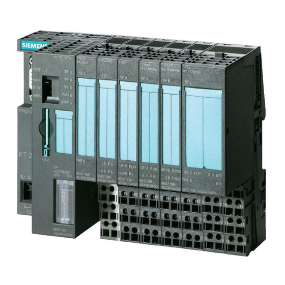
Page 21: View Of The Et 200S Distributed I/O System With The Im 151-7 Cpu
Product Overview View The figure below shows a sample configuration of an ET 200S with an IM 151-7 CPU. Interface module PM-E power module Power module for the Reversing starter IM 151-7 CPU for electronic modules PM-D motor starter DP master module Electronic modules Direct-on-line starter Terminating module... - Page 22 Product Overview Features of the IM 151-7 CPU compared to other modules The IM 151-7 CPU interface module has the following special features: S The interface has PLC functionality (integrated CPU component with 48 kByte working memory). S The interface module can only be operated with fitted load memory (MMC). S The interface module can be enhanced with up to 63 I/O modules from the ET 200S range.
-
Page 23: Guide To The Et 200S Manuals
Product Overview Guide to the ET 200S manuals They utilize the following components ... The components of ET 200S are described in various manuals. They are parts of various documentation packages. The figure below shows possible configuration variants of the ET 200S and the necessary manuals in the documentation packages. -
Page 24: Components And The Manuals Required For Them (Continued)
Product Overview The ET 200S consists of the Order numbers for You will require the in- following components: the necessary do- formation contained in cumentation pak- the following manuals: kages or manuals ET 200S Distributed 6ES7 151-1AA10-8xA0 IM 151 I/O System ET 200S Motor Starters ET 200S Safety-Integra- ted SIGUARD System... -
Page 25: Topics Of The Manuals In The Et 200S Manual Package
Product Overview Where do you find what information? The following table will help you find the information you require quickly. It tells you which manual you need to refer to and which section deals with the topic you are interested in. Table 1-2 Topics of the manuals in the ET 200S manual package Manual... -
Page 26: Glossary
Applications Glossary The frame for configuration and parameter assignment for the IM 151-7 CPU can be found on the Internet at http://www.ad.siemens.de/simatic-cs ET 200S fail-safe modules You can find the ET 200S Distributed I/O System, Fail-Safe Modules manual in the S7 F Systems (order number 6ES7 988-8FA10-8xA0) documentation package and in the S7 Distributed Safety documentation package (order number 6ES7 988-8FB10-8xA0). -
Page 27: Getting Started
Getting Started Introduction This guide takes you through the 10 commissioning steps required to set up a functioning IM 151-7 CPU application by running through a concrete example. In this way, you will get to know the basic functions of your IM 151-7 CPU for the following: S Hardware and software S Stand-alone operation (MPI) - Page 28 2-19 S7-300 Required material and tools Quan- Article Order number (SIEMENS) tity S7-300 system, consisting of power supply (PS), CPU with various DP interface (here: CPU 315 2-DP), digital input module (DI) in slot 4 and digital output module (DO) in slot 5, incl.
-
Page 29: 1St Step: Installing The Im 151-7 Cpu (Et 200S) And S7-300
Getting Started 1st step: Installing the IM 151-7 CPU (ET 200S) and S7-300 Description quence Install the S7-300 as described in Installation Manual for Automation System S7-300, Setting If you want to operate the IM 151-7 CPU using a dedicated power supply, hang the PS in the mounting rail of the S7-300 and push in until it engages. -
Page 30: 2Nd Step: Wiring The Im 151-7 Cpu (Et 200S) And S7-300
Getting Started 2nd step: Wiring the IM 151-7 CPU (ET 200S) and S7-300 Description quence Wire the S7-300 as described in Installation Manual for Automation System S7-300, Setting Lengthen the connections for each of the 4 buttons using a cable. Strip 6 mm of insulation from the free cable ends and cap the ends with wire end ferrules. -
Page 31: Illustration Showing The S7-300
Getting Started Illustration showing the S7-300 (the power supply wiring for the DI and DO is not shown; the PD is connected to the S7-300) Powersupply Switch for setting Programming device Mode selector switch Profile rail ON/OFF system voltage with STEP 7 Software Clamp for Switches Programming device cable... -
Page 32: 3Rd Step: Commissioning The Im 151-7 Cpu (Et 200S)
Getting Started 3rd step: Commissioning the IM 151-7 CPU (ET 200S) Note On initial commissioning (condition when supplied) of the ET 200S, the CPU can be accessed using the MPI address 2, HSA 31 and 187.5 kBaud. Description quence Switch on the PS of the IM 151-7 CPU. Result: The 24 VDC LED lights up on the PS. -
Page 33: 4Ht Step: Configuring The Im 151-7 Cpu For Stand-Alone Operation (Mpi)
Getting Started 4ht step: Configuring the IM 151-7 CPU for stand-alone operation (MPI) Action Result quence Does the wizard for a new project appear in the If yes: Close the wizard because the SIMATIC Manager? IM 151-7 CPU is not supported by the project wizard. - Page 34 Getting Started Action Result quence Navigate through the appropriate IM 151-7 CPU to PM. Drag the PM whose order number matches the order number on your PM, and drop it onto slot 4. Repeat point 8 for the DI (slot 5) and DO (slot 6) Select the command Save and compile in the The hardware configuration is compiled and Station menu.
-
Page 35: 5Th Step: Programming The Im 151-7 Cpu
Getting Started 5th step: Programming the IM 151-7 CPU Action Result quence In the SIMATIC Manager, navigate through IM151-7 CPU and S7 Program to the Blocks container. Double-click on the OB 1 symbol in the The LAD/FBD/STL Editor used to edit the right-hand part of the window. -
Page 36: 6Th Step: Test Run
Getting Started 6th step: Test Run Action Result quence In the SIMATIC Manager, click on Blocks in the Blocks is highlighted. left-hand part of the window. Right-click in the right-hand part of the window The blocks OB82 and OB86 appear next to and insert an empty organization block with the the block OB 1. -
Page 37: 7Th Step: Upgrading The Im 151-7 Cpu As An I Slave And Commissioning The S7-300
Getting Started 7th step: Upgrading the IM 151-7 CPU as an I slave and commissioning the S7-300 Description quence Remove the connector of the PD cable from the IM 151-7 CPU. Start the Set PD/PC Interface program as described under step 3, point 4. Change the configuration of the PD/PC interface as follows: Confirm the settings with OK and close the ”Set PD/PC Interface”... -
Page 38: 8Th Step: Configuring The Im 151-7 Cpu As An I Slave And The S7-300
Getting Started 8th step: Configuring the IM 151-7 CPU as an I slave and the S7-300 as a DP master Change the configuration of the IM 151-7 CPU as follows: Action Result quence Start the Hardware Configuration program for The Editor used to edit the hardware the IM 151-7 CPU as described in step 4. - Page 39 Getting Started Configure the S7-300-CPU as follows: Action Result quence In the SIMATIC Manager, select the project Getting Started in the left-hand part of the window. Insert the new S7-300 station into the project as described in step 4, point 3. In the SIMATIC Manager, click on the S7-300(1) The Hardware symbol appears in the station in the left-hand part of the window.
- Page 40 Getting Started Action Result quence In the bottom left-hand part of the Hardware Configuration Program window, double-click on CPU 315-2 DP (line 2). In the window that then appears, click on the Properties button on the General tab. In the ”MPI Network” window that then appears, check whether the address is set to 2.
- Page 41 Getting Started Action Result quence In the window from point 9, click on the Edit button and complete the form for line 1 as shown in the illustration. Then confirm with OK. Then click on the second line in the Properties – MPI/DP window and complete the form for line 2 as shown in the illustration.
-
Page 42: 9Th Step: Programming The Im 151-7 Cpu And The S7-300 Cpu
Getting Started 9th step: Programming the IM 151-7 CPU and the S7-300 CPU Action Result quence In the SIMATIC Manager, navigate to the The LAD/FBD/STL Editor used to edit the block container of the ET 200S. OB 1 block opens. Double-click on the OB1 symbol in the right-hand part of the window. - Page 43 Getting Started Action Result quence Complete the OB 1 of the S7-300 CPU as follows: How it Works: The status of the button connected to E1.1 of the S7-300 is checked and stored temporarily in the memory marker M13.0. The entire memory byte MB13 is transferred to the peripheral output byte PQB12.
- Page 44 Getting Started This results in the following communication paths: S7-300 IM 151-7 CPU I1.1 M13.0 MB13 PQB12 PQW12 PIW128 PIB128 MB12 M12.0 A2.1 M13.1 E1.0 PQB128 MB13 PIW12 PQW128 MB12 PIB12 A5.0 M12.1 ET 200S IM 151-7 CPU Interface Module 2-18 A5E00058783-04...
-
Page 45: 10Th Step: Commissioning And Test Run Of The Im 151-7 Cpu And S7-300
Getting Started 2.10 10th step: Commissioning and test run of the IM 151-7 CPU and S7-300 Action Result quence In the SIMATIC Manager, navigate to the block container of the S7-300 and insert an empty organization block with the name OB 86 into the block container. - Page 46 Getting Started Action Result quence Start the Set PD/PC Interface program as described under step 3, point 4. Change the configuration of the PD/PC interface as follows: Confirm the settings with OK and close the ”Set PD/PC Interface” program. Open the front panel of the S7-300-CPU. Connect the IM 151-7 CPU to the DP interface of the S7-300-CPU using a PROFIBUS-DP cable.
- Page 47 Getting Started Action Result quence Set the mode selector on the IM 151-7 CPU to The STOP LED of the IM goes out. The RUN. RUN LED starts to flash and then remains lit. The SF LED lights up. Set the mode selector on the S7-300-CPU to RUN. The STOP LED of the S7 goes out.
- Page 48 For more information on getting started we also recommend: Getting Started: First Steps and Exercises With STEP 7 V5.x. All of these manuals can be downloaded free of charge from the Siemens homepage (Customer Support, Automation). ET 200S IM 151-7 CPU Interface Module...
-
Page 49: Addressing
Addressing Principles of Data Transfer Between the DP Master and the IM 151-7 CPU This chapter contains information on the addressing of I/O modules and data transfer between the DP master and the IM 151-7 CPU. The following alternatives are available for addressing the I/O modules: S Slot-oriented address allocation: Slot-oriented address allocation is the default form of addressing, in which STEP 7 allocates a fixed module base address to each slot number. -
Page 50: Slot-Oriented Addressing Of The I/O Modules
Addressing Slot-Oriented Addressing of the I/O Modules Slot-Oriented Address Allocation In slot-oriented addressing (default addressing) each slot number in a module is allocated an address area in the IM 151-7 CPU. Depending on the type of I/O module, the addresses are digital or analog (see Table 3-1). -
Page 51: Addresses Of The Et 200S I/O Modules
Addressing Address Assignment Depending on the slot, 1 byte is reserved for digital I/Os and 16 bytes are reserved for analog I/Os in the address areas of the IM 151/7 CPU for each I/O module (maximum of 63). The table below indicates the default address assignment for analog and digital modules per slot. -
Page 52: User-Oriented Addressing Of The I/O Modules
Addressing Example of Slot-Oriented Address Assignment for I/O Modules The figure below illustrates a sample ET 200S configuration, showing an example of the address allocation for I/O modules. The addresses for the I/O modules are predefined in default addressing. Slot numbers 1 to 3 ET 200S 151-7... -
Page 53: Data Interchanger With The Dp Master
Addressing Advantages Advantages of user-defined address allocation: S Optimum utilization of the address areas available, since ”address gaps” between the modules do not occur. S When creating standard software, you can specify addresses that are independent of the configuration of the ET 200S station. Data interchanger with the DP Master User data transfer via an intermediate memory The user data is located in an intermediate memory in the IM 151-7 CPU. - Page 54 Addressing Data consistency You define data consistency as byte, word, or overall consistency per address area. Consistency can amount to up to 32 bytes/16 words per address area. DP diagnostic address in STEP 7 When the ET 200S is configured with STEP 7, two diagnostic addresses are set. The ET 200S receives information on the status of the DP master or on a bus interruption by means of these diagnostic addresses (see Section 7.5).
-
Page 55: Accessing The Intermediate Memory In The Im 151-7 Cpu
Addressing Accessing the intermediate memory in the IM 151-7 CPU Access in the user program The following table tells you how to access the intermediate memory in the IM 151-7 CPU from the user program. Table 3-2 Accessing the address areas Access dependent on data The following applies consistency... -
Page 56: Addressing Interface In Step 7 V5.1 (Extract)
When the IM 151-7 CPU is configured with STEP 7 for operation in the S5 or in non-Siemens systems, it is clear that only the logical addresses within the slave CPU are allocated. The addresses are then assigned in the master system using the specific configuration tool of the master system. - Page 57 Addressing Sample Program Below you will see a sample program for data interchange between the DP master and the DP slave. You can find the addresses in Table 3-3. SFCs 14 and 15 are called by specifying the logical address in hexadecimal format.
- Page 58 Addressing User Data Transfer in STOP Mode The user data in the intermediate memory is processed differently depending on whether the DP master or the DP slave (IM 151-7 CPU) goes into STOP mode. S If the IM 151-7 CPU goes into STOP mode: The data in the intermediate memory (outputs only from the slave’s viewpoint) of the IM 151-7 CPU are overwritten with “0”;...
-
Page 59: Et 200S In The Profibus Network
ET 200S in the PROFIBUS Network Introduction You can integrate the ET 200S with the IM 151-7 CPU as a node in a PROFIBUS network. This chapter contains a description of a typical network configuration with the IM 151-7 CPU. It also tells you which functions can be executed via the PD or OP on the ET 200S and which options are available for direct connection. -
Page 60: Example Of A Profibus Network
ET 200S in the PROFIBUS Network ET 200S in the PROFIBUS network Structure of a PROFIBUS network The figure below illustrates the basic structure of a PROFIBUS network with one DP master and several DP slaves. S7-300 (DP master) ET 200S ET 200X OP 25** ET 200S... -
Page 61: Setting The Mode Of The Dp Interface At The Im 151-7 Cpu
ET 200S in the PROFIBUS Network Access to the ET 200S The IM 151-7 CPU is a passive/active bus node. The programs and configuration of the IM 151-7 CPU can be transferred to the IM 151-7 CPU by choosing ”Load PLC”... -
Page 62: Behavior Of The Im 151-7 Cpu Depending On The Dp Interface Setting
ET 200S in the PROFIBUS Network Depending on the DP interface setting, the IM 151-7 CPU will behave in the following way: Table 4-1 Behavior of the IM 151-7 CPU depending on the DP interface setting DP Interface of the IM 151-7 CPU Passive Active Transmission rate detection... -
Page 63: The Pd/Op Accesses The Et 200S Via The Dp Interface In The Dp Master
ET 200S in the PROFIBUS Network Examples for the connection of the PD/OP on the ET 200S S The PD/OP is connected to the PROFIBUS-DP interface of the DP master, but can be connected just as well to any other station in the DP network, including the ET 200S. -
Page 64: Network Components
ET 200S in the PROFIBUS Network Network components To connect the ET 200S to the PROFIBUS-DP network, you need the following network components: Table 4-2 Network components Purpose Network components Order numbers To set up the network Cables (e.g. 2-core, 6XV1 830-0AH10 shielded or 5-core, (2-core) -
Page 65: Connecting The Dp Network
ET 200S in the PROFIBUS Network Example of the use of network components The figure below shows the example from Figure 4-3 with the use of the network components. Connecting the bus cable to the bus connector is described in the Product Information document for the bus connector. -
Page 66: Profibus Address
ET 200S in the PROFIBUS Network PROFIBUS address Features Use the PROFIBUS address to specify the address at which the IM 151-7 CPU is contacted on the PROFIBUS-DP. Prerequisites S The permitted PROFIBUS-DP addresses are 1 to 125. S Each address can be allocated only once on the PROFIBUS-DP. Startup without DP configuration on the Micro Memory Card (MMC) (initial startup) Following POWER ON, the coexistent interface on the IM 151-7 CPU powers up... -
Page 67: Functions Via The Pd/Op
ET 200S in the PROFIBUS Network Functions via the PD/OP You can use the PD to: S Configure the IM 151-7 CPU with ET 200S modules and put them into operation on the PROFIBUS-DP S Program the IM 151-7 CPU S Execute test functions such as ”Monitor/Modify Variables”... -
Page 68: Principle Behind Forcing
ET 200S in the PROFIBUS Network Force test function In the case of the IM 151-7 CPU, you can preset the inputs and the outputs in the process image with fixed values using the ”Force” function. The values (force values) you have preset can still be controlled in the IM 151-7 CPU by the user program and by PD/OP functions. - Page 69 ET 200S in the PROFIBUS Network Application example Prerequisite: There is no direct I/O access in your user program. If, for example, an enable sensor (f) in your system is defective and it continually indicates a logical 0 to your user program, for example, via input 1.2, you can bridge this sensor by forcing the input to 1, ensuring that your system continues to operate.
-
Page 70: Direct Communication
ET 200S in the PROFIBUS Network Direct communication You can configure the IM 151-7 CPU as an intelligent slave with STEP 7 V5.1 for direct communication. Direct communication is a special communication relationship between PROFIBUS-DP nodes. Principle Direct communication is characterized by the fact that the PROFIBUS-DP nodes ”listen in”... - Page 71 ET 200S in the PROFIBUS Network Functionality in direct communication The IM 151-7 CPU offers the following functionality in direct communication: S Transmitter: As an I slave, the IM 151-7 CPU sends the process outputs, configured for direct communication, to all bus nodes as a broadcast frame. Other recipients filter the relevant data from this broadcast frame.
- Page 72 ET 200S in the PROFIBUS Network ET 200S IM 151-7 CPU Interface Module 4-14 A5E00058783-04...
-
Page 73: Et 200S In The Mpi Network
ET 200S in the MPI Network Introduction You can integrate the ET 200S with the IM 151-7 CPU as a node in an MPI network. This chapter contains a description of a typical network configuration with the IM 151-7 CPU. Section 4.4 describes which functions can be executed on the IM 151-7 CPU using a PD or OP. -
Page 74: Example Of An Mpi Network
ET 200S in the MPI Network ET 200S in the MPI network Structure of an MPI network The figure below shows an example of an MPI network configuration. ET 200S ET 200S OP 25** The ET 200S can be configured and programmed from this PD ** Operating and monitoring functions can be executed on the ET 200S 3, 4, 10, 11 MPI addresses of the nodes Figure 5-1... -
Page 75: Mpi Address
ET 200S in the MPI Network MPI address Features With the MPI address, you determine the address under which the IM 151-7 CPU is accessed in the MPI network. Prerequisites S The permitted MPI addresses are 0 to 126. S Each address can be allocated only once on the MPI network. Recommendations for MPI addresses S Assign MPI addresses greater than ”2”... - Page 76 ET 200S in the MPI Network ET 200S IM 151-7 CPU Interface Module A5E00058783-04...
-
Page 77: Example Of The Structure With The Im 151-7 Cpu Acting As The Dp Master
DP Master Module Introduction In combination with the DP master module, you can operate the IM 151-7 CPU as a DP master. In this case, the IM 151-7 CPU can be S integrated in a PROFIBUS network as an I slave or S operated in stand-alone mode (MPI). -
Page 78: Mounting The Dp Master Module
DP Master Module Mounting the DP master module When you expand your interface module IM 151-7 CPU with a DP master module, you can use the IM 151-7 CPU as a DP master. Procedure Step Description The IM 151-7 CPU is installed on the mounting rail. Hang the DP master module onto the mounting rail to the right of the IM 151-7 CPU. -
Page 79: Commissioning The Im 151-7 Cpu As A Dp Master
DP Master Module Commissioning the IM 151-7 CPU as a DP master Prerequisites for commissioning S The PROFIBUS subnet has been configured. S The DP slaves have been prepared for operation (see the relevant DP slave manual). S The IM 151-7 CPU must be configured as a DP master prior to commissioning. This means that you must use STEP 7 –... - Page 80 DP Master Module Behavior of the IM 151-7 CPU upon commissioning S The DP master module is mounted and the IM 151-7 CPU has been configured as a DP master ⇒ IM 151-7 CPU goes into RUN mode with master functionality S The DP master module is mounted and the IM 151-7 CPU has not been configured as a DP master ⇒...
-
Page 81: Event Recognition Of The Im 151-7 Cpu As A Dp Master
DP Master Module Start-up of the IM 151-7 CPU as a DP master When it starts up, the IM 151-7 CPU compares the preset configuration of the DP master system with the actual configuration. If the preset configuration + the actual configuration, the CPU goes into RUN mode. - Page 82 DP Master Module Status/controlling, programming via PROFIBUS-DP You can program the CPU or execute the PD functions listed in Chap. 4.4 via the DP master interface. Note The use of status and control via the DP master interface extends the DP cycle. Equidistance As of STEP 7 V5.2, with the IM 151-7 CPU and DP master module, you can parameterize bus cycles of the same length (equidistant) for PROFIBUS subnets.
-
Page 83: Commissioning And Diagnostics
Commissioning and Diagnostics Configuring the IM 151-7 CPU with STEP 7 This chapter describes how to configure an ET 200S for the IM 151-7 CPU with STEP 7. Resetting the memory of the IM 151-7 CPU In certain situations you must reset the memory of the IM 151-7 CPU. This chapter describes these circumstances and the procedure for resetting the memory of the CPU component. -
Page 84: Configuration Options
IM 151-7 CPU, integrated as a standard intelligent slave via GSD in a non-Siemens tool Note If you wish to operate the IM 151-7 CPU as a standard I slave via the GSD file, then you should not activate the commissioning/test mode checkbox in the DP interface properties when configuring this slave CPU in STEP 7. - Page 85 8. The two stations must then be reloaded to start master-slave communication. Configuration in a non-Siemens system Using the DDB file you can also integrate the IM 151-7 CPU in non-Siemens systems as a standard I slave. In this case the diagnostic frame consists of the...
-
Page 86: Ways To Reset The Memory
Commissioning and Diagnostics Resetting the memory of the IM 151-7 CPU When do you reset the memory of the IM 151-7 CPU? The memory of the IM 151-7 CPU must be reset S to erase retentive areas (memory markers, times, counters) S if the IM 151-7 CPU requests a memory reset by flashing the STOP LED at 0.5 Hz The following are possible reasons for the MRES request:... -
Page 87: How To Use The Mode Selector To Reset The Memory
Commissioning and Diagnostics STOP Max. 3 s Min. 3 s STOP STOP STOP STOP STOP MRES MRES MRES MRES MRES Figure 7-1 How to use the mode selector to reset the memory Is the STOP LED not flashing at memory resetting? Does the STOP LED not flash during memory reset or do other indicators come on? You must repeat steps 2 and 3. - Page 88 Commissioning and Diagnostics Note If the CPU cannot copy the contents of the memory module (MMC) and requests a memory reset: S Remove the MMC. S Reset the CPU memory. S Read out the diagnostic buffer. You can read out the diagnostic buffer with the PD (see the STEP 7 Online Help). ET 200S IM 151-7 CPU Interface Module A5E00058783-04...
-
Page 89: Commissioning And Startup Of The Im 151-7 Cpu As An I Slave
Commissioning and Diagnostics Commissioning and startup of the IM 151-7 CPU as an I slave An example of how to commission the IM 151-7 CPU as an I slave and its behavior when it starts up is described below. Information on how to commission the IM 151-7 CPU as the DP master is found in Chapter 6.2. - Page 90 Commissioning and Diagnostics Loading the user program When commissioning the ET 200S, you can download the user program to the IM 151-7 CPU in the following ways: S The program is downloaded from the PD/PC to the memory module (MMC) inserted in the IM 151-7 CPU by means of the ”Load User Program”...
-
Page 91: Diagnostics Using Leds
Commissioning and Diagnostics Diagnostics using LEDs LEDs The RUN, STOP, ON, BF, SF and FRCE LEDs of the IM 151-7 CPU display important information on the states to the user. The IM 151-7 CPU has the following 6 LEDs: S ”SF” LED (System Fault) for indicating the presence of a fault in the ET 200S S ”BF”... -
Page 92: Led Display For Profibus-Dp (Im 151-7 Cpu Is An I Slave)
Commissioning and Diagnostics Diagnosis of DP functionality using the ”BF” and ”SF” LEDs If the ”BF” and ”SF” LEDs light up or flash, the ET 200S is not configured correctly. The tables below shows you the possible error indications together with their meanings and the necessary action. -
Page 93: Led Display For Profibus-Dp (Im 151-7 Cpu Is A Master)
Commissioning and Diagnostics The table 7-5 shows the LED states for DP master operation. Table 7-5 LED display for PROFIBUS-DP (IM 151-7 CPU is a master) “BF” LED “SF” LED Description Cause Error handling on IM 151-7 DP master module No connection to Bus connection Check that the... -
Page 94: Diagnostic Addresses For The Dp Master And Et 200S
Commissioning and Diagnostics Diagnostics via diagnostic address with STEP 7 Malfunctions that occur in the ET 200S are indicated by the ”SF” LED, and the cause is entered in the diagnostic buffer of the IM 151-7 CPU. Either the CPU enters STOP mode, or you can respond to errors by means of error or interrupt OBs in the user program. -
Page 95: Responses To Operating Mode Changes And Interruptions In User Data Transfer In The Dp Master And The Et 200S With The Im 151-7 Cpu As An I Slave
Commissioning and Diagnostics Event identification The table below indicates how the DP master or the IM 151-7 CPU of the ET 200S identifies changes in operating mode and interruptions in user data transfer. Table 7-6 Responses to operating mode changes and interruptions in user data transfer in the DP master and the ET 200S with the IM 151-7 CPU as an I slave What happens ... -
Page 96: Evaluation Of Run-Stop Transitions In The Dp Master/ Et 200S With
Commissioning and Diagnostics Evaluation in the user program The table below indicates how you can evaluate e.g. RUN-STOP transitions in the DP master (CPU 315-2 DP; 6ES7 315-2AF03-0AB0) and in the ET 200S. Table 7-7 Evaluation of RUN-STOP transitions in the DP master/ ET 200S with IM 151-7 CPU as the I slave In the DP master In the ET 200S (IM 151-7 CPU) -
Page 97: Format Of The Slave Diagnostic Data
Commissioning and Diagnostics Slave diagnostics with IM 151-7 CPU used as an intelligent slave Structure of the diagnostic frame Byte 0 Byte 1 Station status 1 to 3 Byte 2 Byte 3 Master PROFIBUS address High byte Byte 4 Manufacturer ID Byte 5 Low byte Byte 6... -
Page 98: Structure Of Station Status 1 (Byte 0)
Commissioning and Diagnostics 7.6.1 Station status 1 to 3 Definition Station status 1 to 3 provides an overview of the status of a DP slave. Station status 1 Table 7-8 Structure of station status 1 (byte 0) Description Remedy 1: DP slave cannot be addressed by Is the correct DP address configured for the DP master. -
Page 99: Structure Of Station Status 2 (Byte 1)
Commissioning and Diagnostics Station status 2 Table 7-9 Structure of station status 2 (byte 1) Description 1: DP slave must be parameterized again and reconfigured. 1: A diagnostic message has arrived. The DP slave cannot continue operation until the error has been rectified (static diagnostic message). 1: This bit is always ”1”... -
Page 100: Structure Of The Master Profibus Address (Byte 3)
Commissioning and Diagnostics 7.6.2 Master PROFIBUS address Definition The DP address of the DP master is stored in the master PROFIBUS address diagnostic byte: S The master that parameterized the DP slave S The master that has read and write access to the DP slave Master PROFIBUS address Table 7-11 Structure of the master PROFIBUS address (byte 3) Description... -
Page 101: Structure Of The Module Diagnosis For The Im 151-7 Cpu
Commissioning and Diagnostics 7.6.4 Module diagnostics Definition The module diagnosis indicates for which of the configured address areas of the intermediate memory an entry has been made. Structure The following figure shows the structure of the module diagnosis for the maximum number of configured address areas. -
Page 102: Module Status
Commissioning and Diagnostics 7.6.5 Module status Definition The module status indicates the status of the configured address areas and expands on the module diagnosis as regards the configuration. The module status begins after the module diagnosis and comprises max. 13 bytes. ET 200S IM 151-7 CPU Interface Module 7-20 A5E00058783-04... -
Page 103: Structure Of The Module Status
Commissioning and Diagnostics Structure The module status of the IM 151-7 CPU is structured as follows: 6 5 4 Bit no. Byte x Length of the module status, including byte x (max. 13 bytes) Code for the station diagnosis 6 5 4 Bit no. -
Page 104: Structure Of The Interrupt Status
Commissioning and Diagnostics 7.6.6 Interrupt status Definition The interrupt status of the station diagnosis provides detailed information about a DP slave. The station diagnosis begins at byte y and can comprise max. 20 bytes. Structure The following figure shows the structure and content of the bytes for a configured address area of the intermediate memory. -
Page 105: Byte Y+4 To Y+7 For The Diagnostic Interrupt
Commissioning and Diagnostics Structure of the interrupt data with process interrupt (from Byte y+4 onwards) With the process interrupt (in byte y+1, code 02 stands for a process interrupt), the 4 byte interrupt information which you transfer in the intelligent slave with the SFC 7 ”DP_PRAL”... -
Page 106: Byte Y+4 To Y+7 For Diagnostic Interrupt (Sfb 75)
Commissioning and Diagnostics Structure of the interrupt data when a diagnostic interrupt is generated by the SFB 75 in the intelligent slave (from Byte y+4 onwards) 6 5 4 Bit no. Diagnostic data Byte y+4 0: Module ok fixed 1: Module fault by definition 6 5 4 Bit no. -
Page 107: Diagnostic Data Of The Electronic Modules
Commissioning and Diagnostics Diagnostic data of the electronic modules 7.7.1 Evaluating diagnostic data of the electronic modules in the user program In this section This section describes the structure of the diagnostic data in the system data. You must be familiar with this structure if you want to evaluate the diagnostic data of the electronic modules in the STEP 7 user program. -
Page 108: Structure Of The Diagnostic Data Using A 4 Channel Mixed Module As An Example
Commissioning and Diagnostics Structure of the diagnostic data Example: 4 channel mixed module Byte 0 Module fault Byte 1 Module class Byte 2 B#16#00 Byte 3 B#16#00 Byte 4 Channel type Byte 5 B#16#20 Length diagn. information Information block Byte 6 Number of channels Byte 7 Faulty channels... -
Page 109: Bytes 0 And 1 Of The Diagnostic Data
Commissioning and Diagnostics 7.7.2 Structure and content of the diagnostic data bytes 0 to 7 The structure and content of the individual bytes of the diagnostic data are described below. The following generally applies: If an error occurs, the corresponding bit is set to ”1”. Bytes 0 and 1 5 4 3 2 1 Byte 0... -
Page 110: Bytes 4 To 7 Of The Diagnostic Data
Commissioning and Diagnostics Bytes 4 to 7 5 4 3 2 1 Byte 4 Channel type B#16#7B: Input module B#16#7C: Output module B#16#7D: PM, FM, VA (motor starter) Mixed module? 0: No 1: Yes; the diagnostic data for the inputs follows; the diagnostic data for the outputs is contained in bytes 12, 16, 20 or 24 onwards (depends on the channel number of the inputs) -
Page 111: Single Fault Of A Channel
Commissioning and Diagnostics 7.7.3 Channel-specific diagnostic data from byte 8 onwards From byte 8 onwards, data record 1 contains the channel-specific diagnostic data. The figures below show the assignment of the diagnostic byte for a channel and a channel group of the specific module. The following generally applies: If an error occurs, the corresponding bit is set to ”1”. -
Page 112: Example: Et 200S Module: 2 Ai U (6Es7 134-4Fb00-0Ab0) Each With Diagnostics For Channel 0 And 1
Commissioning and Diagnostics 7.7.4 Example: ET 200S module: 2 AI U (6ES7 134-4FB00-0AB0) each with diagnostics for channel 0 and 1 The table below shows examples of diagnostic message evaluation for the specified module. Byte Value Description number B#16#0D Module fault, external fault, channel fault exists B#16#15 Channel information exists;... -
Page 113: Functions Of The Im 151-7 Cpu
Functions of the IM 151-7 CPU In this chapter In this chapter you will find: S Important features of the IM 151-7 CPU for the PROFIBUS-DP S A list of the CPU functions of the IM 151-7 CPU that you can call with STEP 7, such as the integrated clock, blocks for the user program and parameters that can be set Chapter overview... -
Page 114: Attributes From The Device Database (Ddb) File
(configuration with COM PROFIBUS) S You are using the ET 200S with a non-SIMATIC DP master (configuration with a non-Siemens tool). You can download the DDB file from the Internet. You will find all the DDB files under ”Downloads” on the SIMATIC Customer Support web site: http://www.ad.siemens.de/csi/gsd... - Page 115 Functions of the IM 151-7 CPU Table 8-1 Attributes from the device database (DDB) file, continued Feature DP code word to IM 151-7 CPU IEC 61784-1:2002 Ed1 CP 3/1 Minimum interval between two slave list cycles Min_Slave_Intervall 1(100ms) Modular device Modular_Station Maximum number of modules Max_Module...
-
Page 116: Positions Of The Mode Selector
Functions of the IM 151-7 CPU The mode selector and LEDs Mode selector The mode selector of the IM 151-7 CPU is designed as a 3-step toggle switch (see below): STOP MRES Figure 8-1 Mode selector Positions of the mode selector The positions of the mode selector are explained in the order in which they are arranged on the IM 151-7 CPU. -
Page 117: Leds For Cpu Functionality
Functions of the IM 151-7 CPU Meanings of the LEDs for CPU functionality For the IM 151-7 CPU there are 2 separate LEDs, which indicate the operating mode of the CPU: S RUN S STOP You can obtain information on the power supply of the CPU, on force requests and on general errors via 3 additional LEDs. -
Page 118: Simatic Micro Memory Card
Functions of the IM 151-7 CPU SIMATIC Micro Memory Card Micro Memory Card A SIMATIC Micro Memory Card (MMC) is used as a memory module for the IM 151-7 CPU. The MMC can be used as a load memory and portable data carrier. It is an essential requirement for operating the IM 151-7 CPU. -
Page 119: Available Mmcs
Functions of the IM 151-7 CPU Service life of an MMC The service life of an MMC mainly depends on the following factors: 1. The number of erasing and programming operations 2. External influences such as the ambient temperature At an ambient temperature of up to 60° C, the service life of an MMC with max. 100,000 erase/write operations is 10 years. - Page 120 Functions of the IM 151-7 CPU Formatting the MMC prior to a memory reset In certain exceptional cases, you have to format the MMC: S The module type is not a user module. S The MMC has not yet been formatted, is faulty or the data is corrupted. The content of the MMC has been designated as invalid.
-
Page 121: Position Of The Memory Card Slot For The Mmc On The Im 151-7 Cpu
Functions of the IM 151-7 CPU Inserting/changing the card The MMC is designed so that it can also be removed and inserted when the power is on. The IM 151-7 CPU must, however, be switched to the STOP mode (see the warning on page 8-6). -
Page 122: Firmware Update With Mmc
Functions of the IM 151-7 CPU Firmware update with MMC To update the firmware, proceed as follows: Table 8-5 Firmware update with MMC Step Action required Action by the IM 151-7 CPU Transfer update files to a blank MMC using STEP 7 and your programming device (w 4 MB). -
Page 123: Backing Up The Operating System
Functions of the IM 151-7 CPU Backing up the operating system on the MMC To back up the operating system, proceed as follows: Table 8-6 Backing up the operating system Step Action required Action by the IM 151-7 CPU Insert a new micro memory card The CPU requests a memory (w 4 MB) in the CPU reset... -
Page 124: Memory Areas Of The Im 151-7 Cpu
Functions of the IM 151-7 CPU Memory concept 8.4.1 Memory areas of the IM 151-7 CPU Organization The memory of the IM 151-7 CPU can be divided into three areas: IM 151-7 CPU Working memory Load memory System memory Figure 8-3 Memory areas of the IM 151-7 CPU Load memory The load memory is installed on a SIMATIC micro memory card (MMC). - Page 125 Functions of the IM 151-7 CPU Working memory The working memory is integrated on the CPU and cannot be expanded. It is used to process the codes and data of the user program. Program processing is only performed at the working memory and system memory. The working memory of the CPU is retentive if the MMC is inserted.
-
Page 126: Retentive Behavior Of The Memory Objects
Functions of the IM 151-7 CPU Retentive behavior of the memory objects The following table shows the retentive behavior of the memory objects during the individual operating mode transitions. Table 8-7 Retentive behavior of the memory objects Memory object Operating mode transition STOP →... -
Page 127: Load And Working Memory
Functions of the IM 151-7 CPU 8.4.2 Memory functions Introduction You use the memory functions to generate, modify or erase user programs and individual blocks. The memory functions also allow you to archive your own project data in order to ensure the retentivity of your data. General: Downloading the user program using the PD/PC The complete user program is downloaded to the IM 151-7 CPU from the MMC using the PD/PC. - Page 128 Functions of the IM 151-7 CPU Downloading a user program to the MMC using the PD/PC Case A: Downloading a new user program You have created a new user program. Download the complete program to the MMC using the PD/PC. Case B: Reloading blocks You have already created a user program and downloaded it to the MMC (case A).
- Page 129 Functions of the IM 151-7 CPU Compression Compression fills any gaps between memory objects which are formed by loading and erasing operations in the load and working memory. Contiguous areas of free memory are then available. Compression is possible when the CPU is in both the STOP and RUN mode. Promming (RAM to ROM) With promming, the current values of the data blocks are transferred from the working memory to the load memory where they serve as new initial values for the...
- Page 130 Functions of the IM 151-7 CPU Removing/inserting the MMC The IM 151-7 CPU cannot run if there is no MMC inserted in the IM 151-7 CPU (no load memory available). Practical operation is only possible if an MMC has been inserted and a memory reset has been performed.
- Page 131 Functions of the IM 151-7 CPU Memory reset A memory reset restores defined conditions following removal/insertion of the micro memory card so that the IM 151-7 CPU can be restarted (warm restart). When the memory is reset, the memory administration system of the IM 151-7 CPU is reorganized.
-
Page 132: Address Areas Of The System Memory
Functions of the IM 151-7 CPU 8.4.3 Address areas Overview The system memory of the IM 151-7 CPU id divided into address areas (see the table below). In your program, you use the appropriate operations to address the data directly in the respective address area. Table 8-9 Address areas of the system memory Address area... -
Page 133: Processing Steps Within A Cycle
Functions of the IM 151-7 CPU Process image of the inputs and outputs If the address areas ”inputs” (I) and ”outputs” (O) are addressed in the user program, the signal states on the digital electronic modules are not checked, but instead a memory area in the system memory of the CPU is accessed. - Page 134 Functions of the IM 151-7 CPU Local data The following are stored as local data: S The temporary variables of code blocks S The start information of the organization blocks S Transfer parameters S Intermediate results Temporary variables When creating blocks, you can declare temporary variables (TEMP) which are only available while the block is being processed and are then overwritten again.
-
Page 135: Handling Recipe Data
Functions of the IM 151-7 CPU 8.4.4 Handling data in DBs Recipes A recipe is a collection of user data. A simple recipe concept can be realized using non-process-related data blocks. The recipes should have the same structure (length). There should be one DB for each recipe. -
Page 136: Handling Measured Value Archives
Functions of the IM 151-7 CPU Measured value archives Measured values are created when the user program is processed by the IM 151-7 CPU. These measured values are to be archived and evaluated. Processing sequence of a measured value archive Collecting the measured values: S The measured values in the working memory are collected in a DB (for alternating buffer operation in several DBs) by the IM 151-7 CPU. -
Page 137: Storing/Download Entire Projects On/From Micro Memory Cards
Functions of the IM 151-7 CPU MMC access Note Active system functions SFC 82 to 84 (current access to the MMC) have a major influence on PD functions (e.g. status block, status variable, download block, upload block, open block). Their performance is typically 10 times lower (compared to non-active system functions). -
Page 138: Interfaces
Functions of the IM 151-7 CPU Interfaces The IM 151-7 CPU has a coexistent MPI/DP interface X1. The DP master module has a PROFIBUS-DP master interface X2. The interfaces are described below. MPI interface The MPI (Multi Point Interface) is the interface of the IM 151-7 CPU to a PD/OP and the interface allowing communication in an MPI network. - Page 139 Functions of the IM 151-7 CPU DP master interface The DP master interface on the DP master module is used to connect the distributed I/O (slaves). Transmission rates of up to 12 Mbaud are possible. The DP master interface can be configured to be a DP master or to be inactive. S As a DP master the interface requires a configuration.
-
Page 140: Features Of The Clock
Functions of the IM 151-7 CPU Clock The IM 151-7 CPU has an integrated hardware clock. Setting, reading and programming the clock You set and read the clock using the programming device (see the STEP 7) User Manual) or program the clock in the user program using SFCs (see the System and Standard Functions Reference Manual and Instruction list). -
Page 141: S7 Connections
Functions of the IM 151-7 CPU S7 connections Introduction If S7 modules communicate with each other, a so-called S7 connection is built up between the modules. This forms the communication route. Note Global data communication does not require S7 connections. Each communication connection requires S7 connection resources on the CPU;... - Page 142 Functions of the IM 151-7 CPU Assigning S7 connections The S7 connections on a communications-capable module can be assigned in various ways: Reserving connections during configuration S If, in STEP 7, a CPU is plugged in when the hardware is configured, S7 connections are automatically reserved on this CPU for both the PD and OP communication.
- Page 143 Functions of the IM 151-7 CPU Sequence of the assignment of S7 connections When the system is configured with STEP 7, parameter blocks are generated that are read out when the module is initialized. Thus, the module operating system reserves or assigns the corresponding S7 connections. This means, for example, that an Operator Station cannot access a reserved S7 connection for PD communication.
-
Page 144: Distribution Of The S7 Connections
Functions of the IM 151-7 CPU Distribution of the S7 connections The distribution of the S7 connections of the CPUs are shown in the table below: Table 8-12 Distribution of the S7 connections Communication utility Distribution PD communication So that the assignment of the S7 connections does not depend solely on the sequence in which the various OP communication communication utilities arise, S7 connections can be reserved... -
Page 145: Availability Of The S7 Connections
Functions of the IM 151-7 CPU Availability of the S7 connections The table below shows the S7 connections available on the IM 151-7 CPU. Table 8-13 Availability of the S7 connections Parameters IM 151-7 CPU Total number of S7 connections Reserved for PD communication 1 to 11 Default: 1... -
Page 146: Communication Utilities Of The Im 151-7 Cpu
Functions of the IM 151-7 CPU Communication Communication utilities of the IM 151-7 CPU The selected communication utility influences S the functionality available to the user S whether or not an S7 connection is required S the time at which the connection is set up The user interface can be very different (SFC, SFB, ...) and also depends on the used hardware (SIMATIC-CPU, PC, ...). - Page 147 Functions of the IM 151-7 CPU OP communication OP communication enables data exchange between operator stations (e.g. OP, TP) and communications-capable SIMATIC modules. The utility is possible on MPI and PROFIBUS subnetworks. OP communication provides functions which are required for operation and monitoring.
- Page 148 Functions of the IM 151-7 CPU Global data communication Global data communication enables the cyclic exchange of global data (e.g. I, O, M) between SIMATIC S7-CPUs (unacknowledged data exchange). The data is sent to all CPUs in the MPI subnetwork simultaneously by the CPU. The function is integrated in the operating system of the IM 151-7 CPU.
-
Page 149: Gd Resources Of The Im 151-7 Cpu
Functions of the IM 151-7 CPU GD resources The table below shows the GD resources of the IM 151-7 CPU. Table 8-15 GD resources of the IM 151-7 CPU Parameters IM 151-7 CPU Number of GD circles per CPU Max. 4 Number of transmit GD packets per GD circle Max. -
Page 150: Routing
Functions of the IM 151-7 CPU Routing Access from a PD/PC to stations in another subnetwork As of STEP 7 V5.2 + Service Pack 1, you can reach S7 stations across subnetwork boundaries with the PD/PC when using IM 151-7 CPU and the DP master module, for example to load user programs or a hardware configuration or to perform testing and diagnosis functions. -
Page 151: Routing Gateway
Functions of the IM 151-7 CPU Gateway The gateway from one subnetwork to one or more other subnetworks lies in a SIMATIC station that has interfaces to the respective subnetworks. Thus, in the diagram below, the CPU 31xC-2 DP acts as a router between subnetwork 1 and subnetwork 2. -
Page 152: Routing - Teleservice Application Example
Functions of the IM 151-7 CPU Application example: TeleService As an application example, the following figure shows the teleservice of an S7 station by a PD. The connection is established across subnetwork boundaries and by means of a modem connection. The lower section of the figure show how easily this can be configured in STEP 7. -
Page 153: Data Consistency
Functions of the IM 151-7 CPU 8.10 Data consistency A data area is said to be consistent if it can be read/written by the operating system as a single block. The data that is transmitted together between devices should stem from one processing cycle and thus should form a unit, i.e. be consistent. -
Page 154: Overview Of The Blocks
Functions of the IM 151-7 CPU 8.11 Blocks This section provides an overview of the blocks that run in the IM 151-7 CPU. The operating system is designed for event-driven processing of the user program. The following tables show which organization blocks (OBs) the operating system automatically invokes in response to which events. - Page 155 Functions of the IM 151-7 CPU SFC 55 ”WR_PARM”, SFC 56 ”WR_DPARM”, SFC 57 ”PARM_MOD”, SFC 58 ”WR_REC” The use of SFCs 55 to 58 in conjunction with your IM 151-7 CPU is not recommended owing to the static module parameters. If you do use SFCs 55 to 58 in conjunction with your IM 151-7 CPU, the IM 151-7 CPU could malfunction.
-
Page 156: Parameters
Functions of the IM 151-7 CPU 8.12 Parameters Parameterizable features The properties and responses of the IM 151-7 CPU can be parameterized. You carry out this parameterization on different tabs in STEP 7. Which parameters can be set for the IM 151-7 CPU? The following table contains all the parameter blocks for the IM 151-7 CPU. - Page 157 Functions of the IM 151-7 CPU Table 8-17 Parameter blocks, settable parameters and their ranges for the IM 151-7 CPU, continue Parameter Settable parameters Range blocks Cyclic interrupts Periodicity of the OB 35 (ms) 1 to 60000 Cycle/clock Scan cycle monitoring time (ms) 1 to 6000 memory Cycle load from communication (%)
-
Page 158: Parameterization Of The Reference Junction
Functions of the IM 151-7 CPU 8.13 Parameterization of the reference junction for the connection of thermocouples If you want to use the IM 151-7 CPU in an ET 200S system with thermocouples and reference junctions, set the following parameters in the properties section of the hardware configuration: Table 8-18 Parameterization of the reference junction CPU parameter... -
Page 159: Example Of A Parameterization Dialog Box For The Cpu Module Parameters In Step 7 V5.2 + Sp1
Functions of the IM 151-7 CPU Figure 8-10 Example of a parameterization dialog box for the CPU module parameters in STEP 7 V5.2 + SP1 Reference You can find detailed information on the procedure, the connection system and an example of parameterization in the chapter entitled Analog Electronic Modules in the ET 200S Distributed I/O System manual. -
Page 160: Removal And Insertion Of Modules During Operation
Functions of the IM 151-7 CPU 8.14 Removal and insertion of modules during operation Removing and inserting one module at a time in the case of the IM 151-7 CPU with local ET 200S I/Os is possible during operation and in an energized state. Exceptions The CPU itself must not be removed during operation and in an energized state. -
Page 161: Result Of The Preset/Actual Comparison In Modules That Cannot Be
Functions of the IM 151-7 CPU What happens when modules are inserted during operation If you reinsert a module that has been removed in the ET 200S I/O system during operation, the CPU carries out a preset/actual comparison for the inserted module. This compares the configured module with the one that is actually inserted. -
Page 162: Result Of The Preset/Actual Comparison In The Case Of Parameterizable Modules With The Power Module Switched Off
Functions of the IM 151-7 CPU The following activities only occur if the power module of the inserted module is switched off. Table 8-21 Result of the preset/actual comparison in the case of parameterizable modules with the power module switched off Inserted module 0 configured module Inserted module = configured module OB 83 is called with the corresponding diagnostic buffer entry (event ID 3861... -
Page 163: Switching Power Modules Off And On During Operation
Functions of the IM 151-7 CPU 8.15 Switching power modules off and on during operation What happens when power modules are switched off during operation If the load power voltage to a power module is switched off during operation, the following activities take place: S If you enable diagnostics during parameter assignment for the power module, diagnostic interrupt OB 82 (diagnostic address of the power module) is called... - Page 164 Functions of the IM 151-7 CPU ET 200S IM 151-7 CPU Interface Module 8-52 A5E00058783-04...
-
Page 165: Cycle And Response Times
Cycle and Response Times Introduction In this chapter you will learn what make up the cycle and response times of the ET 200S with the IM 151-7 CPU. You can use the PD to read out the cycle time of your user program (see the STEP 7 user manual). -
Page 166: Component Parts Of The Cycle Time
Cycle and Response Times Cycle time Cycle time – a definition The cycle time is the time that the operating system requires to process a program cycle – i.e. an OB 1 cycle – as well as all the program sections and system activities interrupting this cycle. -
Page 167: Operating System Processing Time In The Scan Cycle Checkpoint
Cycle and Response Times Extending the cycle time Note that the cycle time of a user program is extended by the following: S Time-controlled interrupt handling S Process interrupt handling (see also Section 9.3) S Diagnostics and error handling (see also Section 9.3) Operating system processing time The operating system execution time for the IM 151-7 CPU is found in Table 9-1. -
Page 168: Dependency Of The User Program Scanning Time
Cycle and Response Times User program scanning time: The user program scanning time is made up of the sum of the execution times for the instructions and SFCs called. These execution times can be found in the instruction list. You also have to multiply the user program scanning time by an interface module-specific factor. -
Page 169: With The Im 151-7 Cpu
Cycle and Response Times Response time Response time for the ET 200S with the IM 151-7 CPU The response time is the time from the detection of an input signal at the ET 200S with the IM 151-7 CPU to the modification of an associated output signal via the inputs and outputs of the expansion modules. -
Page 170: Shortest Response Time
Cycle and Response Times Shortest response time The following figure shows you the conditions under which the shortest response time is obtained. Delay of the inputs The status of the observed input changes immediately before reading in the PII. The change in the input signal is therefore taken account of in the PII. -
Page 171: Longest Response Time
Cycle and Response Times Longest response time The following figure shows what the longest response time consists of. Delay of the inputs + DP cycle time at the PROFIBUS-DP While the PII is being read in, the status of the observed input changes. The change in the input signal is no longer taken into account in the PII. -
Page 172: Interrupt Response Times Of The Im 151-7 Cpu (Without Communication)
Cycle and Response Times Interrupt response time Interrupt response time – a definition The interrupt response time is the time from the first occurrence of an interrupt signal to the call of the first instruction in the interrupt OB of the IM 151-7 CPU. The following generally applies: Interrupts of higher priority have precedence. -
Page 173: Technical Specifications
Technical Specifications In this chapter In this chapter you will find: S The technical specifications of the IM 151-7 CPU interface module ET 200S IM 151-7 CPU Interface Module 10-1 A5E00058783-04... -
Page 174: Technical Specifications Of The Im 151-7 Cpu
Technical Specifications 10.1 Technical specifications of the IM 151-7 CPU Order numbers Interface module IM 151-7 CPU: 6ES7 151-7AA10-0AB0 DP master module: 6ES7 138-4HA00-0AB0 SIMATIC micro memory card (MMC): 6ES7 953-8Lxx0-0AA0 (see Section 8.3) Features The IM 151-7 CPU interface module has the following features: S Intelligent slave with RS 485 interface to the PROFIBUS-DP S Stand-alone operation (MPI) possible S 48 kByte working memory, non-expandable, retentive with inserted MMC... -
Page 175: Terminal Assignment For The Interface Module Im 151-7 Cpu
Technical Specifications Terminal assignment for the IM 151-7 CPU Table 10-1 Terminal assignment for the interface module IM 151-7 CPU View Signal name Description 1 – – IM 151-7 CPU IM 151-7 CPU 2 M24 External 24 VDC supply 3 RxD/TxD-P Data line B 4 RTS Request To Send... -
Page 176: Basic Circuit Diagram For The Im 151-7 Cpu
Technical Specifications Basic circuit diagram for the IM 151-7 CPU PROFIBUS-DP master (RS 485) Galvanic isolation DP master module PROFIBUS-DP connection Backplane bus (RS 485) ET 200S STOP Galvanic backplane bus isolation interface module (mP, RAM) STOP MRES Mode selector FRCE Internal power supply... - Page 177 Technical Specifications Technical specifications CPU and product version Preset No retentive timers MLFB 6ES7 151-7AA10-0AB0 Timing range 10 ms to 9990 s Hardware version IEC timers Firmware version V2.1.0 Number Unlimited (limited only by the Matching STEP 7 starting with working memory) programming V5.1 + SP6 (for...
- Page 178 Technical Specifications Configuration rules Number Max. 10 Max. 63 I/O modules per station Monitor block Station width <1 m or <2 m Single sequence Max. 10 A per load group (power module) Breakpoint Master interface module, right, near the Diagnostic buffer IM 151-7 CPU (X2 interface) Number of inputs Max.
- Page 179 Technical Specifications As slave only when Automatic Yes (only with passive the interface is transmission rate interface) active search With the Intermediate 244 I bytes/244 O bytes IM 151-7 CPU as memory the DP master – Address areas 32 with a maximum of Interfaces 32 bytes each * On IM 151-7 CPU (X1)
- Page 180 Technical Specifications Transmission rates Up to 12 Mbaud Galvanic isolation Number of DP Between the supply slaves per station voltage (1L+) and all other circuit Address area Max. 2 kbytes I/ components 2 kbytes O Between User data per DP Max.
- Page 181 Changing IM 151-7 CPU (6ES7 151-7Ax00..) to IM 151-7 CPU (6ES7 151-7AA10-0AB0) If you download your existing user program for the IM 151-7 CPU (6ES7 151-7Ax00-0AB0) to an IM 151-7 CPU (6ES7 151-7AA10-0AB0), you may encounter the following problems: The SFC 56, SFC 57 and SFC 13 may work asynchronously A number of asynchronous SFCs are always processed or, under certain conditions, already processed following the first call (”quasi-synchronous”) on the IM 151-7 CPUs (6ES7 151-7Ax00-0AB0).
- Page 182 Changing IM 151-7 CPU (6ES7 151-7Ax00..) to IM 151-7 CPU (6ES7 151-7AA10-0AB0) S SFC 13 ”DPNRM_DG” This SFC always runs “quasi-synchronously” when called in OB 82. It always runs asynchronously on the IM 151-7 CPU (6ES7 151-7AA10-0AB0). Note In the user program, all that should take place is that the task should be called in the OB 82.
- Page 183 Changing IM 151-7 CPU (6ES7 151-7Ax00..) to IM 151-7 CPU (6ES7 151-7AA10-0AB0) Changed runtimes during program processing If you have created a user program that is optimized for the execution of certain processing times, it is important to note the following when using the IM 151-7 CPU (6ES7 151-7AA10-0AB0): S Program processing in the IM 151-7 CPU is significantly faster.
- Page 184 Changing IM 151-7 CPU (6ES7 151-7Ax00..) to IM 151-7 CPU (6ES7 151-7AA10-0AB0) Replacing an IM 151-7 CPU (6ES7 151-7Ax00-0AB0) with an IM 151-7 CPU (6ES7 151-7AA10-0AB0) in the configuration If the user does not make any changes to the configuration, the functional settings in the configuration are set to default values if an IM 151-7 CPU (6ES7 151-7Ax00-0AB0) is replaced with an IM 151-7 CPU (6ES7 151-7AA10-0AB0).
- Page 185 Changing IM 151-7 CPU (6ES7 151-7Ax00..) to IM 151-7 CPU (6ES7 151-7AA10-0AB0) New functionality of the IM 151-7 CPU (6ES7 151-7AA10-0AB0) S Coexistent MPI/DP interface (active/passive) (see Section 8.5) S DP master interface in combination with the DP master module (see Chapters 6.1 and 8.5) S New memory concept (see Section 8.4) S Global data communication (see Section 8.8)
- Page 186 Changing IM 151-7 CPU (6ES7 151-7Ax00..) to IM 151-7 CPU (6ES7 151-7AA10-0AB0) ET 200S IM 151-7 CPU Interface Module 11-6 A5E00058783-04...
-
Page 187: Position Of The Im 151-7 Cpu In The Cpu Range
Position of the IM 151-7 CPU in the CPU Range In this chapter, you will find out the most important differences to two selected CPUs in the S7-300 SIMATIC family. We will also show you how to rewrite programs you have written for the S7-300-CPUs for the IM 151-7 CPU. -
Page 188: Differences To Selected S7-300 Cpus
Position of the IM 151-7 CPU in the CPU Range 12.1 Differences to selected S7-300 CPUs The following table lists the most important programming differences between two selected CPUs of the S7-300 SIMATIC family and the IM 151-7 CPU. Table 12-1 Differences to selected S7-300 CPUs Features CPU 315-2 DP CPU 315-2 DP IM 151-7 CPU... -
Page 189: Example: Fb With Unpacked Addresses
Position of the IM 151-7 CPU in the CPU Range 12.2 Porting the user program Introduction By porting we mean making available on a distributed basis a program that was previously used centrally on a master. Certain adjustments may be necessary to relocate an existing program partially or completely from a master to an intelligent slave. -
Page 190: Example : Replacements Under Tools ! Rewire
Position of the IM 151-7 CPU in the CPU Range Porting with packed addresses If FBs with packed I/O addresses are copied to the IM 151-7 CPU, the packed addresses there can no longer be assigned to the I/Os of the I/O modules locally because the CPU of the IM 151-7 CPU cannot work with packed addresses. - Page 191 Position of the IM 151-7 CPU in the CPU Range 4. Click OK. This starts rewiring. After rewiring, you can decide in a dialog box whether you want to look at the rewiring information file. The file contains the list of old and new address IDs.
- Page 192 Position of the IM 151-7 CPU in the CPU Range ET 200S IM 151-7 CPU Interface Module 12-6 A5E00058783-04...
- Page 193 Glossary Address An address is the designation for a certain address ID or address area (e.g. input I 12.1; memory word MW 25; data block DB 3). AKKU The accumulators are registers in the ³ CPU that act as an intermediate memory for loading and transfer operations as well as comparison, calculation and conversion operations.
- Page 194 Consistent Data Data that belongs together with respect to its content and that must not be separated is referred to as consistent data. For example, the values from analog modules must always be handled consistently, i.e. the value of an analog module must not be corrupted by reading it out at two different points in time.
- Page 195 S ET 200S, ET 200M, ET 200B, ET 200C, ET 200U, ET 200X, ET 200L S DP/AS-I Link S S5-95U with a PROFIBUS-DP slave interface S Other DP slaves from either Siemens or other vendors The distributed I/O systems are connected to the DP master via PROFIBUS-DP. DP Master A ³...
- Page 196 DP Slave A ³ slave on the PROFIBUS bus system with the PROFIBUS-DP protocol that complies with IEC 61784-1:2002 Ed1 CP 3/1 is referred to as a DP slave. DP Standard The DP standard is the bus protocol of the ET 200 distributed I/O system based on IEC 61784-1:2002 Ed1 CP 3/1.
- Page 197 IM 308-C master interface module and the CPU 315-2 DP. DP slaves can be the distributed I/O devices ET 200S, ET 200B, ET 200C, ET 200M, ET 200X, ET 200U, ET 200L or DP slaves from Siemens or other vendors.
- Page 198 Intelligent DP Slave The defining feature of an intelligent DP slave is that input/output data is not made available to the DP master by a real input/output of the DP slave directly, but by a preprocessing CPU (in this case the IM 151-7 CPU interface module). Interrupt operating system of the CPU recognizes 10 different priority classes that control the processing of the user program.
- Page 199 Glossary Master System All DP slaves that are assigned to a DP master for either reading or writing plus the DP master itself make up the master system. Micro Memory Card Memory module for SIMATIC systems. Can be used as a load memory and portable data carrier.
- Page 200 Organization block Organization blocks (OBs) form the interface between the operating system of the CPU and the user program. The sequence in which the user program is processed is defined in the organization blocks. Parameter 1. Variable of a STEP 7 code block 2.
- Page 201 Glossary PROFIBUS Process Field Bus is a German process and field bus standard, defined in IEC 61784-1:2002 Ed1 CP 3/1. It specifies functional, electrical and mechanical characteristics of a bit serial field bus system. PROFIBUS is available with the protocols DP (the German abbreviation for distributed I/O), FMS (= field bus message specification), PA (= process automation) or TF (= technology (process-related) functions).
- Page 202 Runtime Error Error which occurs during processing of the user program on the programmable controller (i.e. not in the process). Scan Cycle Checkpoint The point during CPU program scanning at which the process image is updated, for example. ³ System Function Slave A slave may only exchange data with a ³...
- Page 203 Glossary SYNC SYNC is a control command of the DP master to a group of DP slaves. By means of the SYNC control command, the DP master causes the DP slave to freeze the current statuses of the outputs. For the following frames, the DP slave stores the output data but the states of the outputs remain unchanged.
- Page 204 Transmission rate The transmission rate is the data transmission speed and specifies the number of transmitted bits per second (transmission rate = bit rate). In the case of the ET 200S, transmission rates of 9.6 kbaud to 12 Mbaud are possible.
- Page 205 Index Communication, 8-45 data consistency, 8-41 Access, to the ET 200S from a PD/PC, 4-3 global data communication, 8-36 Address, Glossary-1 OP communication, 8-35 Address area PD communication, 8-34 data consistency, 3-6 routing, 8-37 for user data transfer, 3-5 S7 basic communication, 8-35 of the expansion modules, 3-3 S7 communication, 8-35 Address areas, 8-20...
- Page 206 Diagnosis Force, 8-5, Glossary-5 module, 7-19 Formatting the MMC, 8-8 station, 7-22 FRCE, LED, 8-5 Diagnostic address, 3-6, 7-12, 7-14 FREEZE, Glossary-5 Diagnostic buffer, Glossary-3 Function, FC, Glossary-5 entry, 7-12 Functions, via PD, 4-9 reading out, 7-5 Diagnostic data, 7-25 Diagnostic interrupt, 7-23, Glossary-3 Diagnostic interrupt response time, 9-8 Gateway, 8-39...
- Page 207 Index MMC, Glossary-7 formatting, 8-8 LED, 7-5 module, 8-6 display, 7-9 service live, 8-7 FRCE, 8-5 Mode indicator, 1-4 RUN, 8-5 ON, 8-5 STOP, 8-5 RUN, 8-5 Mode selector, 8-4 SF, 8-5 memory reset, 7-4 STOP, 8-5 MRES, 8-4 Load instruction, 3-7 RUN, 8-4 Load memory, 8-12, Glossary-6 STOP, 8-4...
- Page 208 Rewiring, 12-4 Routing Parameter, Glossary-8 access to stations in another subnetwork, Parameter assignment frame, configuration, 8-38 8-46 application example, 8-40 Parameters, 8-45 gateway, 8-39 IM 151-7 CPU, 8-44 prerequisites, 8-39 Rules, for addressing, 3-8 connection to ET 200S, 4-5 prerequisites, 4-2, 5-2 LED, 8-5 PD, Glossary-9 mode, 8-5...
- Page 209 Index Station diagnosis, 7-22 Station status 1 to 3, 7-16 Technical specifications STEP 7, Glossary-10 general, 10-2 addressing interface, 3-8 of the IM 151-7 CPU, 10-2 configuring the IM 151-7 CPU, 7-2 PROFIBUS-DP, 8-2 settings, 4-9 Test functions, 4-9 STOP Test run, 2-1, 2-2, 2-10, 2-19 LED, 8-5 Time-of-day interrupts, 8-44...
- Page 210 ET 200S IM 151-7 CPU Interface Module Index-6 A5E00058783-04...
- Page 211 FB 0 to FB 2047 • Quantity Max. 512 Max. 512 Max. 512 Max. 512 • Number range FC 0 to FC 2047 FC 0 to FC 2047 FC 0 to FC 2047 FC 0 to FC 2047 Copyright 2005 by Siemens AG A5E00385826-02...
- Page 212 Product information for A5E00385826-02...