Juniper QFX5100 Hardware Manual
Hide thumbs
Also See for QFX5100:
- Hardware manual (300 pages) ,
- Hardware documentation (966 pages) ,
- Quick start manual (2 pages)
Table of Contents
Advertisement
Quick Links
Download this manual
See also:
Hardware Manual
Advertisement
Table of Contents

Related Manuals for Juniper QFX5100


Summary of Contents for Juniper QFX5100
- Page 1 QFX5100 Switch Hardware Guide Modified: 2017-02-13 Copyright © 2017, Juniper Networks, Inc.
- Page 2 END USER LICENSE AGREEMENT The Juniper Networks product that is the subject of this technical documentation consists of (or is intended for use with) Juniper Networks software. Use of such software is subject to the terms and conditions of the End User License Agreement (“EULA”) posted at http://www.juniper.net/support/eula.html.
-
Page 3: Table Of Contents
QFX5100 Device Hardware Overview ........ - Page 4 AC Power Supply for a QFX5100 Device ....... . .
- Page 5 Connecting Earth Ground to a QFX5100 Device ......110 Connecting AC Power to a QFX5100 Device ......111 Connecting DC Power to a QFX5100 Device .
- Page 6 Powering Off a QFX5100 Device ........
- Page 7 United States ..........226 Nonregulatory Environmental Standards ......226 Copyright © 2017, Juniper Networks, Inc.
- Page 8 QFX5100 Switch Hardware Guide viii Copyright © 2017, Juniper Networks, Inc.
- Page 9 Chassis Components and Descriptions ....... 15 Figure 9: QFX5100-24Q Device Port Panel ....... 16 Figure 10: LEDs on the QSFP+ Uplink Ports .
- Page 10 Figure 40: Port Panel QFX5100-96S Device ......80 Figure 41: Port Panel QFX5100-48S Device ......80 Figure 42: Port Panel QFX5100-48T Device .
- Page 11 Replacing Cooling System Component ......133 Figure 72: Installing a Fan Module in a 1 U QFX5100 Device ....134 Figure 73: Installing a Fan Module in a 2 U QFX5100-96S Device .
- Page 12 Safety and Compliance Information ....... . 187 Figure 94: Placing a Component into an Antistatic Bag ..... 211 Copyright © 2017, Juniper Networks, Inc.
- Page 13 Table 17: Fan Tray LED in a QFX5100 Switch ......51...
- Page 14 QFX5100 Switch Hardware Guide Table 27: AC Power Specifications for a QFX5100 Device ....73 Table 28: AC Power Cord Specifications ....... . . 75 Table 29: DC Power Specifications for a QFX5100 Device .
-
Page 15: About The Documentation
® To obtain the most current version of all Juniper Networks technical documentation, see the product documentation page on the Juniper Networks website at http://www.juniper.net/techpubs/ If the information in the latest release notes differs from the information in the documentation, follow the product Release Notes. -
Page 16: Table 1: Notice Icons
RFC 1997, BGP Communities Attribute Italic text like this Represents variables (options for which Configure the machine’s domain name: you substitute a value) in commands or [edit] configuration statements. root@# set system domain-name domain-name Copyright © 2017, Juniper Networks, Inc. -
Page 17: Documentation Feedback
We encourage you to provide feedback, comments, and suggestions so that we can improve the documentation. You can provide feedback by using either of the following methods: Online feedback rating system—On any page of the Juniper Networks TechLibrary site , simply click the stars to rate the content, http://www.juniper.net/techpubs/index.html and use the pop-up form to provide us with information about your experience. -
Page 18: Requesting Technical Support
7 days a week, 365 days a year. Self-Help Online Tools and Resources For quick and easy problem resolution, Juniper Networks has designed an online self-service portal called the Customer Support Center (CSC) that provides you with the following features: Find CSC offerings: http://www.juniper.net/customers/support/... - Page 19 About the Documentation For international or direct-dial options in countries without toll-free numbers, see http://www.juniper.net/support/requesting-support.html Copyright © 2017, Juniper Networks, Inc.
- Page 20 QFX5100 Switch Hardware Guide Copyright © 2017, Juniper Networks, Inc.
-
Page 21: Overview
PART 1 Overview System Overview on page 3 Chassis Components and Descriptions on page 15 Cooling System and Airflow on page 45 Power Supplies on page 53 Copyright © 2017, Juniper Networks, Inc. - Page 22 QFX5100 Switch Hardware Guide Copyright © 2017, Juniper Networks, Inc.
-
Page 23: System Overview
System Software on page 10 QFX5100 Hardware QFX5100 line of switches offer two compact 1 U models and a 2 U model that provide wire-speed packet performance, very low latency, and rich set of Layer 2 and Layer 3 features. In addition to a high-throughput Packet Forwarding Engine, the performance of the control plane running on all the QFX5100 switches is enhanced by the 1.5 Ghz... -
Page 24: Figure 1: Qfx5100-48S Port Panel
The QFX5100-48S provides full duplex throughput of 1.44 Tbps. The QFX5100-48S has a 1 U form factor and comes standard with redundant fans and redundant power supplies. The switch can be ordered with either ports-to-FRUs or FRUs-to-ports airflow and with AC or DC power supplies. -
Page 25: Figure 2: Qfx5100-48T Port Panel
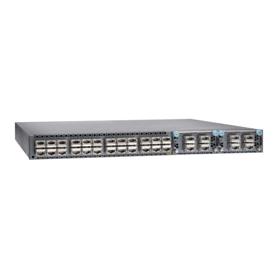
24 high-density QSFP+ ports. Each QSFP+ port can operate as a native 40 Gbps port or as 4 independent 10 Gbps ports. The QFX5100-24Q switch has a 1 U form factor and comes standard with redundant fans and redundant power supplies. -
Page 26: Figure 3: Qfx5100-24Q Port Panel
A master, backup, or line card in a QFX Virtual Chassis. A QFX Series Virtual Chassis allows you to interconnect up to 10 QFX3500, QFX3600, or QFX5100 switches into one logical device and manage the device as a single chassis in a ring topology. -
Page 27: Figure 4: Qfx-Em-4Q Expansion Module
However, when an EX4600-EM-8F is inserted instead of the default QFX-EM-4Q, the new configuration causes the interfaces to temporarily go down. Likewise, when an EX4600-EM-8F is running on the QFX5100-24Q and it is swapped with a QFX-EM-4Q, the interfaces temporarily go down, which can cause a short disruption in traffic. -
Page 28: Figure 6: Qfx5100-24Q-Aa Port Panel With Qfx-Pfa-4Q
VMs directly from the Packet Forwarding Engine. Figure 6: QFX5100-24Q-AA Port Panel with QFX-PFA-4Q The QFX5100-24Q-AA can be used as a standalone switch that supports high frequency statistics collection. Working with Juniper Networks Cloud Analytics Engine, this switch monitors and reports the workload and application behavior across the physical and virtual infrastructure. -
Page 29: Figure 8: Qfx5100-96S Port Panel
In a mixed environment with QFX5100-24Q, QFX5100-98S and EX4300, use the QFX5100-24Q as the spine device and the QFX5100-96S and EX4300 as a leaf devices. You may use the QFX5100-96S as a spine in an all QFX5100-96S VCF or in a VCF that has a mixture of QFX5100-96S and EX4300. -
Page 30: System Software
Layer 3 switching, routing, and security services. Junos OS is installed on a QFX5100 switch’s 32-gigabyte (GB) internal solid state flash drive. The same Junos OS code base that runs on QFX5100 switches also runs on all Juniper Networks EX Series switches, M Series, MX Series, and T Series routers. - Page 31 Chapter 1: System Overview Table 3: QFX5100 Switch Product Numbers (continued) Number of Number Expansion Power of Mgt. P roduct Numbers Ports Modules Supply Ports Airflow QFX5100-24Q-AFO 24 QSFP+ Air Out (ports-to-FRUs) QFX5100-24Q-3AFO 24 QSFP+ Air Out (ports- to-FRUs) QFX5100-24Q-DC-AFI...
-
Page 32: Understanding Hardware Redundancy Of Qfx5100 Device Components And Functionality
Functionality The following hardware components provide redundancy on a QFX5100 switch: Power supplies—The QFX5100 switch has one or two power supplies. Each power supply provides power to all components in the switch. If two power supplies are installed, the two power supplies provide full power redundancy to the device. If one power supply fails or is removed, the second power supply balances the electrical load without interruption. - Page 33 Cooling system—The 1 U models of QFX5100 line of switches have five fan modules; the 2 U QFX5100-96S has three fan modules. If a fan module fails and is unable to keep the QFX5100 switch within the desired temperature thresholds, chassis alarms occur and the QFX5100 switch can shut down.
- Page 34 QFX5100 Switch Hardware Guide Copyright © 2017, Juniper Networks, Inc.
-
Page 35: Chassis Components And Descriptions
Port Panel of a QFX5100-96S Device on page 25 Field-Replaceable Units in a QFX5100 Device on page 28 Access Port and Uplink Port LEDs on a QFX5100 Device on page 29 Management Panel of a QFX5100 Device on page 32... -
Page 36: Port Panel Of A Qfx5100-24Q Device
The QFX5100-24Q device has two module bays for the optional expansion modules, QFX-EM-4Q or EX4600-EM-8F. The QFX-EM-4Q, can add a total of 8 additional QSFP+ ports to the chassis and the EX4600-EM-8F can provide 8 additional 10-Gigabit Ethernet Enhanced Small Form-Factor Pluggable (SFP+) ports. -
Page 37: Switch Ports
Expansion Module adds the switch uplink capacity by 2 for a total of 8 uplinks. To connect a QFX5100-24Q switch as a Node device in a QFabric system, you need: Four QSFP+ uplink ports on each QFX5100-24Q Node device to connect to the data plane network through the QFX3008-I or QFX5100-24Q Interconnect devices. -
Page 38: Channelizing Interfaces (Non-Qfabric)
4 QFX5100 devices can be configured as spines. To connect a QFX5100-24Q device as a member in a QFX Virtual Chassis, you need to cable a pair of ports to link each member in the Virtual Chassis into a ring topology. Each member in the ring has at least one direct Virtual Chassis port (VCP) connection to each directly connected member. -
Page 39: Port Leds
Chapter 2: Chassis Components and Descriptions To connect a QFX5100-24Q device as a spine or leaf device in a VCF, you need to cable a set of ports as VCP connections that link each spine device and leaf device. All spine devices have at least one direct VCP connection to each leaf device in the VCF. -
Page 40: Port Panel Of A Qfx5100-24Q-Aa Device
1280 Gbps output. Any of the 24 ports can be configured as either an uplink port or an access port. The expansion module bay of the QFX5100-24Q switch is located on the port panel. In the expansion module bay, you can install a single double-wide expansion module (QFX-PFA-4Q) or two single-wide optional expansion modules (QFX-EM-4Q and EX4600-EM-8F, in any combination). -
Page 41: Port Panel Of A Qfx5100-48S Device
Installing and Removing QFX5100 Device Hardware Components on page 137 Port Panel of a QFX5100-48S Device The port panel of the QFX5100-48S switch supports up to a maximum of 72 logical 10 GbE ports when operating as a standalone switch. Forty-eight physical ports( through ) support 10 Gigabit Ethernet small form-factor pluggable plus (SFP+) transceivers. -
Page 42: Figure 12: Qfx5100-48S Switch Port Panel
See Interface Specifications for SFP, SFP+, and QSFP+ Transceivers for the QFX Series. To connect a QFX5100-48S switch as a member in a QFX Virtual Chassis, you need a pair of dedicated ports and cables that link each member in the Virtual Chassis into a ring topology. -
Page 43: Port Panel Of A Qfx5100-48T Device
See Interface Specifications for QSFP+ DAC Breakout Cables for the QFX Series. To connect a QFX5100-48T device as a member in a QFX Virtual Chassis, you need a pair of dedicated ports and cables that link each member in the Virtual Chassis into a ring topology. -
Page 44: Figure 13: Qfx5100-48T Switch Port Panel
See Connecting QFX Series Switches in a Virtual Chassis for cabling diagrams. To connect a QFX5100-48T device as a leaf device in a Virtual Chassis Fabric (VCF), you need a pair of dedicated ports and cables that link each spine device and leaf device in the VCF. -
Page 45: Port Panel Of A Qfx5100-96S Device
See Interface Specifications for SFP, SFP+, and QSFP+ Transceivers for the QFX Series. Access port pinouts for the QFX5100-48T switch are the same as the management port connector pinouts for the QFX Series. For more information, see Management Port Connector Pinouts for the QFX Series. -
Page 46: Switch Ports
Channelizing Interfaces The port panel of the QFX5100-96S switch supports up to a maximum of 104 logical 10 GbE ports that can be distributed over 96 small form-factor pluggable plus (SFP+) and 8 quad small-form factor pluggable plus (QSFP+) transceivers . -
Page 47: Virtual Chassis And Virtual Chassis Fabric Support
QFX5100-24Q as the spine device and the QFX5100-96S and EX4300 as a leaf devices. You may use the QFX5100-96S as a spine in an all QFX5100-96S VCF or in a VCF that has a mixture of QFX5100-96S and EX4300. -
Page 48: Field-Replaceable Units In A Qfx5100 Device
Field-Replaceable Units in a QFX5100 Device Field-replaceable units (FRUs) are components that you can replace at your site. The QFX5100 device FRUs are hot-insertable and hot-removable: you can remove and replace one of them without powering off the switch or disrupting the switching function. -
Page 49: Access Port And Uplink Port Leds On A Qfx5100 Device
Chapter 2: Chassis Components and Descriptions Access Port and Uplink Port LEDs on a QFX5100 Device The Link/Activity and Status LED configuration for QFX5100 switches use bi-colored LEDs. The link LED indicates link activity or a fault. The status LED indicates transceiver presence. -
Page 50: Table 7: Qfx5100 Access Port And Uplink Led Locations
QFX5100 Switch Hardware Guide Table 7: QFX5100 Access Port and Uplink LED Locations Model Port Type Indicators Location QFX5100-24Q QSFP+ Link Status QFX5100-48S SFP+ Link Link/Activity Status Status QFX5100-48T 10GBASE-T Link QFX5100-96S SFP+ Link Status Copyright © 2017, Juniper Networks, Inc. -
Page 51: Table 8: Network Port Leds On Sfp+ Ports On A Qfx5100 Switch
Model Port Type Indicators Location Table 8 on page 31 describes how to interpret the SFP+ port LEDs. Table 8: Network Port LEDs on SFP+ Ports on a QFX5100 Switch Color State Description Link/Activity Unlit The port is administratively disabled, there is no power, the link is down, or there is a fault. -
Page 52: Management Panel Of A Qfx5100 Device
Connecting a Fiber-Optic Cable to a QFX Series Device Management Panel of a QFX5100 Device The management panel of the QFX5100 switch is found on the Field Replaceable Unit (FRU) end of the switch as shown in Figure 15 on page 32... -
Page 53: Figure 16: Qfx5100-96S, Fru End
Chapter 2: Chassis Components and Descriptions Figure 16: QFX5100-96S, FRU End Figure 17: Management Panel Components on 1 U QFX5100 1— Status LEDs 4— em0–RJ-45 (1000 Base-T) management Ethernet port ( Some SKUs have an additional SFP management Ethernet port (second 2—... -
Page 54: Figure 18: Management Panel Components On The Qfx5100-96S
QFX5100 Switch Hardware Guide Figure 18: Management Panel Components on the QFX5100-96S 1— Status LEDs 4— em0–RJ-45 (1000 Base-T) management Ethernet port (C0) 2— em1–SFP management Ethernet port (C1) 5— RJ-45 console port (C0N) ) Cage (socket for either 1 GbE copper SFP or fiber SFP) 3—... - Page 55 Chassis Status LEDs on a QFX5100 Device on page 37 USB Port Specifications for the QFX Series on page 91 Cooling System and Airflow in a QFX5100 Device on page 45 AC Power Supply for a QFX5100 Device on page 53...
-
Page 56: Management Port Leds On A Qfx5100 Device
The management ports (labeled for 10/100/1000 Base-T and for 10/100/1000 Base-T and SFP 1000 Base-X connections) on a QFX5100 switch have two LEDs that indicate link status and link activity (see Figure 19 on page 36). The left LED indicates status;... -
Page 57: Chassis Status Leds On A Qfx5100 Device
Connecting a QFX5100 Device to a Network for Out-of-Band Management Chassis Status LEDs on a QFX5100 Device The QFX5100 switch series has four status LEDs on the FRU side of the chassis, next to the management ports (see Figure 20 on page 37). -
Page 58: Table 11: Chassis Status Leds On A Qfx5100 Switch
QFX5100 Switch Hardware Guide Table 11 on page 38 describes the chassis status LEDs on a QFX5100 switch, their colors and states, and the status they indicate. You can view the colors of the three LEDs remotely through the CLI by issuing the operational mode command... -
Page 59: Expansion Modules For Qfx5100 Devices
Expansion Modules for QFX5100 Devices The QFX5100-24Q and QFX5100-24Q-AA devices have two bays on the port panel for optional expansion modules. These expansion modules can be hot-inserted or hot-removed. Expansion modules and transceivers are not shipped with the switch and must be ordered separately. -
Page 60: Ex4600-Em-8F
When the expansion module is inserted into the expansion bay, the chassis detects the additional ports, recognizes them as 10GbE ports, and lights the Status LED. The QFX5100-24Q device is configured for the QFX-EM-4Q by default, but any combination of the two modules is supported. Expansion modules can be hot-inserted or hot-removed. -
Page 61: Qfx-Em-4Q
QFX-EM-4Q The QFX-EM-4Q, provides 4 additional 40-Gigabit Ethernet QSFP+ ports to one of the bays in the QFX5100-24Q or QFX5100-24Q-AA. Port 0 and port 2 can be used for port channelization by configuring the system mode for 104 port mode. -
Page 62: Qfx-Pfa-4Q
QFX5100 Switch Hardware Guide QFX-PFA-4Q The QFX-PFA-4Q, which features a high-performance field-programmable gate array (FPGA), provides four additional QSFP+ ports to the QFX5100-24Q switch. The QFX-PFA-4Q is a double-wide expansion module. Figure 23 on page 42 shows the ports and LEDs on the expansion module. - Page 63 Application-specific status is off. Green Application-specific status is on. Related Installing an Expansion Module in a QFX5100 Device on page 143 Documentation Removing an Expansion Module from a QFX5100 Device on page 146 Installing and Removing QFX5100 Device Hardware Components on page 137 Configuring the System Mode Copyright ©...
- Page 64 QFX5100 Switch Hardware Guide Copyright © 2017, Juniper Networks, Inc.
-
Page 65: Cooling System And Airflow
Both the 1 U and 2 U versions of QFX5100 fan modules have a similar design with different dimensions. The 1 U QFX5100 devices have 5 fan modules numbered 0 through 4 from left to right, where the 2 U, QFX5100-96S device, has 3 fan modules numbered 0 through 2. -
Page 66: Figure 24: 1 U Fan Module Used In Qfx5100 Switches
2 U fan module. Figure 24: 1 U Fan Module Used in QFX5100 Switches Figure 25: 2 U Fan Module Used in QFX5100-96S Switches You remove and replace a fan module from the FRU end of the chassis. The switch continues to operate for a limited period of time (30 seconds) during the replacement of the fan module without thermal shutdown. -
Page 67: Table 15: Fan Modules In Qfx5100 Switches
Chapter 3: Cooling System and Airflow Table 15: Fan Modules in QFX5100 Switches Label on Color of Direction of the Fan Airflow in the Power Fan Module Product SKUs Airflow Diagram Module Module Fan Module Supplies QFX5100-FAN-AFI QFX5100-24Q Figure 26 on page 48... -
Page 68: Figure 26: Air In Airflow Through 1 U Qfx5100 Switch Chassis
QFX5100 Switch Hardware Guide Figure 26: Air In Airflow Through 1 U QFX5100 Switch Chassis Figure 27: Air In Airflow Through 2 U QFX5100 Switch Chassis Copyright © 2017, Juniper Networks, Inc. -
Page 69: Figure 28: Air Out Airflow Through 1 U Qfx5100 Switch Chassis
Chapter 3: Cooling System and Airflow Figure 28: Air Out Airflow Through 1 U QFX5100 Switch Chassis Figure 29: Air Out Airflow Through 2 U QFX5100 Switch Chassis Do Not Install Components with Different Airflow or Wattage in the Switch Do not mix power supplies with different airflow. -
Page 70: Fan Module Status
CAUTION: Do not mix AC and DC power supplies in the same chassis. However if you need to convert a QFX5100 device to have a different airflow, you can change the airflow pattern. To convert an product SKU to an... -
Page 71: Fan Module Led On A Qfx5100 Device
Prevention of Electrostatic Discharge Damage on page 210 QFX5100 Device Hardware Overview on page 3 Installing a Fan Module in a QFX5100 Device on page 133 Removing a Fan Module from a QFX5100 Device on page 134 Fan Module LED on a QFX5100 Device Figure 30 on page 51 shows the location of the LED next to the fan module. - Page 72 QFX5100 Switch Hardware Guide Copyright © 2017, Juniper Networks, Inc.
-
Page 73: Power Supplies
The AC power supply in 1 U QFX5100 switches is 650 W; the AC power supply in the 2 U, QFX5100-96S switch, is 850 W. Both power supplies look identical. Be sure to use the... -
Page 74: Figure 31: 1 U Ac Power Supply In Qfx5100 Switches
4— Ejector lever Figure 32: 2 U AC Power Supply in a QFX5100-96S Switch The power supply provides FRU-to-port or port-to-FRU airflow depending on the product SKU you purchase. On legacy switches, or switches with an LCD, this airflow is called back-to-front and front-to-back. -
Page 75: Dc Power Supply In A Qfx5100 Device
Figure 34 on page 56) are hot-removable and hot-insertable field-replaceable units (FRUs) that you can install in 1 U DC product SKUs of QFX5100 devices without powering off the device or disrupting the switching function. Copyright © 2017, Juniper Networks, Inc. -
Page 76: Figure 34: Dc Power Supply In Qfx5100 Devices
QFX5100 Switch Hardware Guide The DC power supply in 1 U product SKUs of QFX5100 is 650 W with dual feeds for power resiliency. The DC power supply in the 2 U product SKU, QFX5100-96S, is 850 W with dual feeds for power resiliency. Both power supplies have a similar design. See... -
Page 77: Ac Power Supply Leds On A Qfx5100 Device
“Removing a Power Supply from a QFX5100 Device” on page 140. Related DC Power Supply LEDs on a QFX5100 Device on page 58 Documentation Management Panel of a QFX5100 Device on page 32 Field-Replaceable Units in a QFX5100 Device on page 28... -
Page 78: Dc Power Supply Leds On A Qfx5100 Device
QFX5100 Switch Hardware Guide Figure 37: AC Power Supply LEDs on a QFX5100 Switch AC OK DC OK Fault Table 19 on page 58 describes the LEDs on the AC power supplies. Table 19: AC Power Supply LEDs on a QFX5100 Switch... -
Page 79: Figure 38: Dc Power Supply Faceplate On A Qfx5100 Switch
Chapter 4: Power Supplies Figure 38: DC Power Supply Faceplate on a QFX5100 Switch 1— Input LED 3— Fault LED 2—Output LED CAUTION: The V+ terminals are shunted internally together, as are the V- terminals. The same polarity terminal can be wired together from the same source to provide an additional current path in a higher power chassis. - Page 80 QFX5100 Switch Hardware Guide Copyright © 2017, Juniper Networks, Inc.
-
Page 81: Site Planning, Preparation, And Specifications
PART 2 Site Planning, Preparation, and Specifications Preparation Overview on page 63 Power Specifications and Requirements on page 73 Transceiver and Cable Specifications on page 79 Pinout Specifications on page 91 Copyright © 2017, Juniper Networks, Inc. - Page 82 QFX5100 Switch Hardware Guide Copyright © 2017, Juniper Networks, Inc.
-
Page 83: Preparation Overview
CHAPTER 5 Preparation Overview Site Preparation Checklist for a QFX5100 Device on page 63 Environmental Requirements and Specifications for a QFX5100 Device on page 64 General Site Guidelines on page 66 Site Electrical Wiring Guidelines on page 66 Planning a Virtual Chassis Fabric Deployment on page 67... -
Page 84: Environmental Requirements And Specifications For A Qfx5100 Device
General Site Guidelines on page 66 Installing and Connecting a QFX5100 Device on page 97 Mounting a QFX5100 Device in a Rack or Cabinet on page 99 Environmental Requirements and Specifications for a QFX5100 Device The switch must be installed in a rack or cabinet. It must be housed in a dry, clean, well-ventilated, and temperature-controlled environment. -
Page 85: Preparation Overview
Articles 110-16, 110-17, and 110-18 of the National Electrical Code, ANSI/NFPA 70. Related Clearance Requirements for Airflow and Hardware Maintenance for a QFX5100 Device Documentation on page 71 Installing and Connecting a QFX5100 Device on page 97... -
Page 86: General Site Guidelines
Improperly installed wires cause radio frequency interference (RFI). Damage from lightning strikes occurs when wires exceed recommended distances or pass between buildings. Electromagnetic pulses (EMPs) caused by lightning damage unshielded conductors and electronic devices. Copyright © 2017, Juniper Networks, Inc. -
Page 87: Planning A Virtual Chassis Fabric Deployment
Planning a Virtual Chassis Fabric Deployment A Virtual Chassis Fabric (VCF) architecture supports up to 20 interconnected devices that are managed as a logical single device. Supported platforms in a VCF are QFX5100, QFX3600, QFX3500, and EX4300. Although the architecture has a powerful auto-provisioning option, which allows you to plug and play the devices, careful planning of the deployment can avoid unexpected results. - Page 88 Power Measure the distance between external power sources and switch installation site. Calculate the power consumption and “AC Power Specifications for a QFX5100 requirements. Device” on page 73 AC Power Specifications for a QFX3600 or QFX3600-I Device AC Power Specifications for a QFX3500 Device...
-
Page 89: Rack Requirements For A Qfx5100 Device
Site Preparation Checklist for a QFX3500 Device Site Preparation Checklist for EX4300 Switches Rack Requirements for a QFX5100 Device All QFX5100 devices are designed to be installed on four-post racks. The QFX5100-96S device can also be installed on two-post racks. Rack requirements consist of:... -
Page 90: Table 25: Rack Requirements For The Qfx5100 Device
Documentation Rack-Mounting and Cabinet-Mounting Warnings on page 196 Clearance Requirements for Airflow and Hardware Maintenance for a QFX5100 Device on page 71 Mounting a QFX5100 Device in a Rack or Cabinet on page 99 Copyright © 2017, Juniper Networks, Inc. -
Page 91: Cabinet Requirements For A Qfx5100 Device
Chapter 5: Preparation Overview Cabinet Requirements for a QFX5100 Device You can mount the QFX5100 device in an enclosure or cabinet that contains a four-post 19-in. open rack as defined in Cabinets, Racks, Panels, and Associated Equipment (document number EIA-310-D) published by the Electronics Industry Association. -
Page 92: Figure 39: Clearance Requirements For Airflow And Hardware Maintenance For A Qfx5100 Device
Leave at least 24 in. (61 cm) both in front of and behind the QFX5100 device. For service personnel to remove and install hardware components, you must leave adequate space at the front and back of the switch. -
Page 93: Power Specifications And Requirements
AC Power Cord Specifications for a QFX Series Device on page 74 DC Power Specifications for a QFX5100 Device on page 75 Grounding Cable and Lug Specifications for a QFX5100 Device on page 76 AC Power Specifications for a QFX5100 Device Table 27 on page 73 describes the AC power specifications for a QFX5100 device. -
Page 94: Ac Power Cord Specifications For A Qfx Series Device
QFX5100 Switch Hardware Guide Table 27: AC Power Specifications for a QFX5100 Device (continued) Item Specification Maximum power consumption QFX5100-24Q 365 W QFX5100-48S 365 W QFX5100-48T 395 W QFX5100-96S 470 W Related AC Power Cord Specifications for a QFX Series Device on page 74... -
Page 95: Dc Power Specifications For A Qfx5100 Device
General Safety Guidelines and Warnings on page 187 General Electrical Safety Guidelines and Warnings on page 209 Prevention of Electrostatic Discharge Damage on page 210 AC Power Supply for a QFX5100 Device on page 53 QFX10002 AC Power Specifications QFX5200 AC Power Specifications... -
Page 96: Grounding Cable And Lug Specifications For A Qfx5100 Device
(EMI) requirements. To ground a QFX5100 device, connect a grounding cable to earth ground and then attach it to the chassis grounding points. -
Page 97: Power Specifications And Requirements
The grounding lug provided accommodates 14–10 AWG (2–5.3 mm²) stranded wire. The grounding cable that you provide for a QFX5100 device must be 14 AWG (2 mm²), minimum 60° C wire, or as permitted by the local code. - Page 98 QFX5100 Switch Hardware Guide Copyright © 2017, Juniper Networks, Inc.
-
Page 99: Transceiver And Cable Specifications
DAC breakout cables (DACBO). The QFX5100-48S has 6 QSFP+ ports; the QFX5100-96S has 8 QSFP+ ports; the QFX5100-24Q has 24 built-in QSFP+ ports that can all be used as uplinks. The You can also add two QFX-EM-4Q expansion modules to the QFX5100-24Q for additional QSFP+ uplink ports. -
Page 100: Figure 40: Port Panel Qfx5100-96S Device
QFX5100 Switch Hardware Guide QFX5100-24Q–has 24 QSFP+ access ports that can be configured to operate as 10-Gigabit Ethernet interfaces or as a single 40-Gigabit Ethernet interface. QFX5100-24Q-AA–has 24 QSFP+ access ports that can be configured to operate as 10-Gigabit Ethernet interfaces or as a single 40-Gigabit Ethernet interface. -
Page 101: Figure 43: Port Panel Qfx5100-24Q Device
QFX-PFA-4Q installed) 2—QSFP+ access or uplink ports (24) You can find information about the optical transceivers supported on your Juniper device by using the Hardware Compatibility Tool. In addition to transceiver and connection type, the optical and cable characteristics–where applicable–are documented for each transceiver. -
Page 102: Cable Specifications For Qsfp+ And Qsfp28 Transceivers
QFX5100 Switch Hardware Guide Related Port Panel of a QFX5100-24Q Device on page 16 Documentation Port Panel of a QFX5100-24Q-AA Device on page 20 Port Panel of a QFX5100-48S Device on page 21 Port Panel of a QFX5100-48T Device on page 23... -
Page 103: Table 31: Qsfp+ Mpo Fiber-Optic Crossover Cable Pinouts
Interface Support for the QFX10002 Documentation Cable Specifications for Console and Management Connections for the QFX Series Table 32 on page 84 lists the specifications for the cables that connect the QFX Series to a management device. Copyright © 2017, Juniper Networks, Inc. -
Page 104: Signal Loss In Multimode And Single-Mode Fiber-Optic Cables
Connecting a QFX3500 Device to a Network for Out-of-Band Management Connecting a QFX3100 Director Device to a Network for Out-of-Band Management Connecting a QFX5100 Device to a Network for Out-of-Band Management Connecting a QFX5200 to a Network for Out-of-Band Management... -
Page 105: Attenuation And Dispersion In Fiber-Optic Cable
When chromatic dispersion is at the maximum allowed, its effect can be considered as a power penalty in the power budget. The optical power budget must allow for the sum of component attenuation, power penalties (including those from dispersion), and a safety margin for unexpected losses. Copyright © 2017, Juniper Networks, Inc. -
Page 106: Calculating The Fiber-Optic Cable Power Budget For A Qfx Series Device
) greater than zero indicates that the power budget is sufficient to operate the receiver and that it does not exceed the maximum receiver input power. This means the link will work. A (P ) that is zero or negative indicates insufficient power Copyright © 2017, Juniper Networks, Inc. -
Page 107: Table 33: Estimated Values For Factors Causing Link Loss
For information about the actual amount of signal loss caused by equipment and other factors, see your vendor documentation for that equipment. Calculate the (P ) by subtracting (LL) from (P – LL = P Copyright © 2017, Juniper Networks, Inc. -
Page 108: Copper Cable Specifications For Qfx5100-48T Switches
84 Copper Cable Specifications for QFX5100-48T Switches The QFX5100-48T switches have 10GBASE-T interfaces that use various types of copper network cables. To achieve optimal performance, you must use cables that conform to IEEE 802.3-2012 specifications for connections for 10GBASE-T network ports. -
Page 109: Table 34: Cable Specification For 10Gbase-T Network Ports
STP/UTP ANSI/TIA/EIA-568-A 328 ft 1-100 CAT 6 ANSI/TIA/EIA-568-B.2-1 (100 m) 1-250 CAT 6A ANSI/TIA/EIA-568-B2-10 1-500 (STP/UTP) Related Port Panel of a QFX5100-48T Device on page 23 Documentation QFX5100 Device Hardware Overview on page 3 Copyright © 2017, Juniper Networks, Inc. - Page 110 QFX5100 Switch Hardware Guide Copyright © 2017, Juniper Networks, Inc.
-
Page 111: Pinout Specifications
RJ-45 Management Port Connector Pinout Information on page 93 USB Port Specifications for the QFX Series The following Juniper Networks USB flash drives have been tested and are officially supported for the USB port in the QFX Series: RE-USB-1G-S—1-gigabyte (GB) USB flash drive (except QFX3100 Director device) RE-USB-2G-S—2-GB USB flash drive (except QFX3100 Director device) -
Page 112: Console Port Connector Pinout Information
CD Input Data carrier detect CTS Input Clear to send Related Connecting a Device to a Management Console by Using an RJ-45 Connector on page 120 Documentation Configuring the Console Port Type (CLI Procedure) Copyright © 2017, Juniper Networks, Inc. -
Page 113: Rj-45 Management Port Connector Pinout Information
Chapter 8: Pinout Specifications RJ-45 Management Port Connector Pinout Information Table 36 on page 93 provides the pinout information for the RJ-45 connector for the management port on Juniper Networks devices. Table 36: RJ-45 Management Port Connector Pinout Information Signal Description... - Page 114 QFX5100 Switch Hardware Guide Copyright © 2017, Juniper Networks, Inc.
-
Page 115: Initial Installation And Configuration
Initial Installation and Configuration Unpacking and Mounting the Switch on page 97 Connecting the Switch to Power on page 109 Connecting the Switch to the Network on page 119 Performing Initial Configuration on page 129 Copyright © 2017, Juniper Networks, Inc. - Page 116 QFX5100 Switch Hardware Guide Copyright © 2017, Juniper Networks, Inc.
-
Page 117: Unpacking And Mounting The Switch
“Connecting AC Power to a QFX5100 Device” on page 111 Connecting DC Power to a QFX5100 Device on page 114 Registering Products—Mandatory for Validating SLAs Depending on how you plan to use the QFX5100 device, do one of the following: Copyright © 2017, Juniper Networks, Inc. -
Page 118: Unpacking A Qfx5100 Device
“Configuring a QFX5100 Device” on page 129. If you are using the QFX5100 device as a Node device in a QFX3000-G QFabric system, see QFX3000-G QFabric System Installation Overview for information about the steps to install and configure your QFX3000-G QFabric system. -
Page 119: Mounting A Qfx5100 Device In A Rack Or Cabinet
Installing and Connecting a QFX5100 Device on page 97 Mounting a QFX5100 Device in a Rack or Cabinet You can mount all QFX5100 switches on a four post 19-in. rack or cabinet using the mounting kit provided with the device. -
Page 120: Before You Begin Rack Installation
Two -Post Procedure on page 104 Before You Begin Rack Installation Before you begin mounting a QFX5100 switch in the rack or cabinet: Ensure that you understand how to prevent electrostatic discharge (ESD) damage. “Prevention of Electrostatic Discharge Damage” on page 210. -
Page 121: Four-Post Procedure
If you are installing the QFX5100 switch above 60 in. (152.4 cm) from the floor, you can remove the power supplies and fan modules to minimize the weight before attempting to install the switch. -
Page 122: Figure 46: Attaching Mounting Rails To The Qfx5100-24Q
QFX5100 Switch Hardware Guide Figure 46: Attaching Mounting Rails to the QFX5100-24Q Figure 47: Attaching Mounting Rails to the QFX5100-48S Figure 48: Attaching Mounting Rails to the QFX5100-96S Attach the mounting rail to the switch using the mounting screws (and cage nuts and washers if your rack requires them). -
Page 123: Figure 49: Attach 1 U Switch To Rack
Use the four mounting screws (and cage nuts and washers if your rack requires them) to attach each blade to the rack. (Use eight front-mounting screws for the QFX5100-96S.) Tighten the screws. See Figure 51 on page 104. -
Page 124: Two -Post Procedure
Two -Post Procedure You can center mount a QFX5100-96S on two posts of a 19-in. rack or cabinet by using the short mounting brackets provided with the switch. Other product SKUs of the QFX5100 are not recommended for a two post installation. -
Page 125: Virtual Chassis Fabric Installation Overview
Related Rack-Mounting and Cabinet-Mounting Warnings on page 196 Documentation Connecting AC Power to a QFX5100 Device on page 111 Connecting Earth Ground to a QFX5100 Device on page 110 Virtual Chassis Fabric Installation Overview For best results, ensure you review and understand the Virtual Chassis Fabric (VCF) configuration options. - Page 126 EX4300 (leaf) An all QFX5100 installation is the optimum VCF configuration. When multiple models of the QFX5100 are in a VCF, use QFX5100-24Q, if available, as the spine. Installations with all members within the same line of switches (for example, QFX5100-24Q, QFX5100-48S, QFX5100-48T, and QFX5100-96S) are homogeneous configurations.
- Page 127 Connect and configure one of the management ports (C0) or (C1) to a management switch as the Virtual Management Ethernet interface. Using this interface, you can configure and manage the devices in the VCF. See Connecting a QFX5100 Device to a Network for Out-of-Band Management.
- Page 128 QFX5100 Switch Hardware Guide Copyright © 2017, Juniper Networks, Inc.
-
Page 129: Connecting The Switch To Power
CHAPTER 10 Connecting the Switch to Power Connecting Earth Ground to a QFX5100 Device on page 110 Connecting AC Power to a QFX5100 Device on page 111 Connecting DC Power to a QFX5100 Device on page 114 Copyright © 2017, Juniper Networks, Inc. -
Page 130: Connecting Earth Ground To A Qfx5100 Device
(see Figure 54 on page 111). Before you connect earth ground to the protective earthing terminal of a QFX5100 device, ensure that a licensed electrician has attached an appropriate grounding lug to the grounding cable. -
Page 131: Connecting Ac Power To A Qfx5100 Device
Connecting DC Power to a QFX5100 Device on page 114 Connecting AC Power to a QFX5100 Device The QFX5100 is shipped from the factory with two power supplies. Each power supply is a hot-removable and hot-insertable field-replaceable unit (FRU) when the second power supply is installed and running. - Page 132 53). Install the power supply in the chassis. For instructions on installing a power supply in a QFX5100 device, see “Installing a Power Supply in a QFX5100 Device” on page 138. NOTE: Each power supply must be connected to a dedicated power source outlet.
-
Page 133: Figure 56: Connecting An Ac Power Cord To An Ac Power Supply In A 1 U Qfx5100
If the amber fault LED is lit, remove power from the power supply, and replace the power supply (see “Removing a Power Supply from a QFX5100 Device” on page 140 ). Do not remove the power supply until you have a replacement power supply ready: the power supplies or a blank cover panel must be installed in the switch to ensure proper airflow. -
Page 134: Connecting Dc Power To A Qfx5100 Device
AC Power Supply LEDs on a QFX5100 Device on page 57 Connecting DC Power to a QFX5100 Device The QFX5100 is shipped from the factory with two power supplies. Each power supply is a hot-removable and hot-insertable field-replaceable unit (FRU) when the second power supply is installed and running. - Page 135 Install the power supply in the chassis. For instructions on installing a power supply in a QFX5100 device, see “Installing a Power Supply in a QFX5100 Device” on page 138. Ensure that you have the following parts and tools available: DC power source cables (14–16 AWG) with ring lug (Molex 190700069 or equivalent)
- Page 136 Figure 58 on page 117 Figure 59 on page 117 The QFX5100 is designed to operate with a DC power supply that has a single, non-redundant, feed input. For source redundancy, two DC power supplies must be installed in QFX5100; connect source (A) to one power supply and connect source (B) to the second power supply.
-
Page 137: Figure 58: Dc Power Supply Faceplate For A Qfx5100 Device
Do not connect the terminals to different sources. Figure 59: Securing Ring Lugs to the Terminals on the QFX5100 DC Power Supply Replace the terminal block cover. - Page 138 To check the current FPGA version, issue the command. show chassis firmware Related DC Power Supply in a QFX5100 Device on page 55 Documentation DC Power Supply LEDs on a QFX5100 Device on page 58 Copyright © 2017, Juniper Networks, Inc.
-
Page 139: Connecting The Switch To The Network
Connecting a Device to a Management Console by Using an RJ-45 Connector on page 120 Connecting QFX Series and EX Series Switches in a QFX Virtual Chassis on page 121 Connecting a QFX5100 Device in a Virtual Chassis Fabric on page 127 Connecting a Device to a Network for Out-of-Band Management You can monitor and manage these devices by using a dedicated management channel. -
Page 140: Connector
PC directly to the device, use a combination of the RJ-45 to DB-9 female adapter supplied with the device and a USB to DB-9 male adapter. You must provide the USB to DB-9 male adapter. Copyright © 2017, Juniper Networks, Inc. -
Page 141: Connecting Qfx Series And Ex Series Switches In A Qfx Virtual Chassis
Documentation Connecting QFX Series and EX Series Switches in a QFX Virtual Chassis In a QFX Virtual Chassis, you can connect up to 10 standalone QFX5100, QFX3600, QFX3500, and EX4300 switches into a QFX Series Virtual Chassis and manage the interconnected switches as a single chassis. -
Page 142: Valid Configurations
Valid Configurations Valid configurations are: All QFX5100 members–in a ring topology this is Virtual Chassis; in a spine and leaf topology this is a Virtual Chassis Fabric (VCF). For a cabling example of spine and leaf, “Connecting a QFX5100 Device in a Virtual Chassis Fabric” on page 127. -
Page 143: Cabling Qfx3500 Switches In A Qfx Virtual Chassis
A mixture of QFX5100, QFX3600, QFX3500, and EX4300 members. EX4300 switches as the master or backup is not supported; use QFX5100 switches in these roles whenever possible. An all EX4300 member is simply considered an EX4300 Virtual Chassis. See Understanding EX4300 Virtual Chassis. -
Page 144: Cabling Qfx3600 Switches In A Qfx Virtual Chassis
36 37 38 39 40 41 42 43 44 45 46 47 Cabling QFX3600 Switches in a QFX Virtual Chassis Figure 67 on page 125 for a diagram of configuring an exclusive QFX3600 Virtual Chassis. Copyright © 2017, Juniper Networks, Inc. -
Page 145: Cabling A Mixed Qfx Virtual Chassis
C1 S Cabling a Mixed QFX Virtual Chassis A mixed QFX Virtual Chassis is a mixture of QFX5100 , QFX3500, QFX3600, or EX4300 Series switches in a ring topology. Always configure a QFX5100 as the master and backup devices when they are available. See... -
Page 146: Figure 69: Qfx3500 And Qfx3600 Mixed Using Both 40G Ports And 10G Ports
QFX3600-16Q C0 S OK / C1 S QFX3600-16Q C0 S OK / C1 S Figure 70: QFX5100 Master Connecting QFX3600 and QFX3500 Using 40G Ports as VCPs 34 35 36 37 38 39 40 41 42 43 44 45 46 47... -
Page 147: Connecting A Qfx5100 Device In A Virtual Chassis Fabric
An all QFX5100 installation is the optimum VCF configuration. When multiple models of the QFX5100 are in a VCF, use QFX5100-24Q, if available, as the spine. Installations with all members within the same line of switches (for example, QFX5100-24Q, QFX5100-48S, QFX5100-48T, and QFX5100-96S) are homogeneous configurations. -
Page 148: Figure 71: Two Spine Virtual Chassis Fabric With Six Leaf Devices
QFX5100 Switch Hardware Guide Figure 71 on page 128 shows two QFX5100-24Q spine devices connected to six leaf devices of various product models, all using all QSFP+ ports as VCPs. Figure 71: Two Spine Virtual Chassis Fabric with Six Leaf Devices... -
Page 149: Performing Initial Configuration
Configuring a QFX5100 Device on page 129 Configuring a QFX5100 Device You must perform the initial configuration of the QFX5100 switch through the console port using the command-line interface (CLI). Before you begin connecting and configuring a QFX5100 switch, set the following parameter values on the console server or PC: Baud Rate—9600... - Page 150 Enable telnet service. [edit] root@# set system services SSH NOTE: When Telnet is enabled, you cannot log in to a QFX5100 switch through Telnet using root credentials. Root login is allowed only for SSH access. Enable SSH service for root login.
-
Page 151: Installing, Maintaining, And Replacing Components
Components Replacing Cooling System Component on page 133 Replacing Power Supply on page 137 Replacing Expansion Module on page 143 Replacing Transceivers and Fiber-Optic Cable on page 149 Removing the Switch on page 157 Copyright © 2017, Juniper Networks, Inc. - Page 152 QFX5100 Switch Hardware Guide Copyright © 2017, Juniper Networks, Inc.
-
Page 153: Replacing Cooling System Component
LCD, this airflow is called front to back and back to front. Before you install a fan module in a QFX5100 device, ensure that you have taken the necessary precautions to prevent electrostatic discharge (ESD) damage (see “Prevention... -
Page 154: Removing A Fan Module From A Qfx5100 Device
SKU with the airflow marking on the handle to ensure that you are installing a fan module with the same airflow direction as the chassis. The fan modules are designed so that they can only be inserted into the QFX5100 product SKU that supports the same airflow type. See “Cooling System... -
Page 155: Figure 74: Removing A Fan Module From A 1 U Qfx5100 Device
Chapter 13: Replacing Cooling System Component Before you remove a fan module from a QFX5100 device, ensure that you have taken the necessary precautions to prevent electrostatic discharge (ESD) damage (see “Prevention of Electrostatic Discharge Damage” on page 210). Ensure that you have the following parts and tools available to remove a fan module... -
Page 156: Figure 75: Removing A Fan Module From A 2 U Qfx5100-96S Device
QFX5100 Switch Hardware Guide Figure 75: Removing a Fan Module from a 2 U QFX5100-96S Device NOTE: When a fan module is removed, the CLI message Fan/Blower is Absent is logged in the system log, and the system raises a minor alarm. -
Page 157: Replacing Power Supply
“Removing a Fan Module from a QFX5100 Device” on page 134. To install an SFP+ or QSFP+ transceiver in a QFX5100 device, follow the instructions in Installing a Transceiver in a QFX Series Device. To remove an SFP+ or QSFP+ transceiver Copyright © 2017, Juniper Networks, Inc. -
Page 158: Installing A Power Supply In A Qfx5100 Device
Before you install a power supply in a QFX5100 device, ensure that you have taken the necessary precautions to prevent electrostatic discharge (ESD) damage (see “Prevention of Electrostatic Discharge Damage”... -
Page 159: Figure 76: Installing A Power Supply In A 1 U Qfx5100 Device
Figure 76: Installing a Power Supply in a 1 U QFX5100 Device Figure 77: Installing a Power Supply in a QFX5100-96S Device... -
Page 160: Removing A Power Supply From A Qfx5100 Device
Before you remove a power supply from a QFX5100 device, ensure that you have taken the necessary precautions to prevent electrostatic discharge (ESD) damage (see “Prevention of Electrostatic Discharge Damage”... -
Page 161: Figure 78: Removing A Power Supply From A 1 U Qfx5100 Device
Place the power supply in the antistatic bag or on the antistatic mat placed on a flat, stable surface. Figure 78: Removing a Power Supply from a 1 U QFX5100 Device Figure 79: Removing a Power Supply from a QFX5100-96S Device... - Page 162 QFX5100 Switch Hardware Guide Copyright © 2017, Juniper Networks, Inc.
-
Page 163: Replacing Expansion Module
Removing an Expansion Module from a QFX5100 Device on page 146 Installing an Expansion Module in a QFX5100 Device The QFX5100-24Q device allows up to two expansion modules to be added to the port panel to increase port density. The QFX5100-24Q device holds two bays of expansion modules that can be mixed and matched as desired. -
Page 164: Figure 82: Qfx-Pfa-4Q Expansion Module
ESD grounding strap. If a grounding strap is not available, follow the alternative grounding method described in Step 1 of the following procedure. Phillips (+) screwdriver, number 2 To install an expansion module in a QFX5100-24Q or a QFX5100-24Q-AA device (see Figure 83 on page 145 Figure 84 on page... -
Page 165: Figure 83: Installing A Qfx-Em-4Q Expansion Module In A Qfx5100-24Q
5 seconds, the interfaces on the expansion module might not come Raise the handle and tighten the captive screws by using your fingers or the screwdriver. For the QFX5100-24Q-AA, retract the ejector handles and tighten the captive screws by using your fingers or the screwdriver (see Figure 84 on page 145). -
Page 166: Removing An Expansion Module From A Qfx5100 Device
NOTE: When you install the QFX-PFA-4Q expansion module in a QFX5100-24Q-AA switch and reboot the switch, the two NIC ports in the NIC inside the QFX5100-24Q-AA switch are enabled automatically. When you install other expansion modules (QFX-EM-4Q or EX4600-EM-8F), the NIC... - Page 167 Hold the handle and gently pull the expansion module toward you and out of the module slot. For a QFX5100-24Q-AA switch, unscrew the captive screws of the ejector handles and pull the expansion module toward you and out of the module slot (see Figure 86 on page 148).
-
Page 168: Figure 85: Removing A Qfx-Em-4Q Expansion Module From A Qfx5100-24Q
Figure 86: Removing a QFX-PFA-4Q Expansion Module from a QFX5100-24Q-AA Device Related Installing an Expansion Module in a QFX5100 Device on page 143 Documentation Installing and Removing QFX5100 Device Hardware Components on page 137 Field-Replaceable Units in a QFX5100 Device on page 28 QFX5100 Device Hardware Overview on page 3 Copyright ©... -
Page 169: Replacing Transceivers And Fiber-Optic Cable
(JTAC) can help you diagnose the source of the problem. Your JTAC engineer might recommend that you check the third-party optic or cable and potentially replace it with an equivalent Juniper Networks optic or cable that is qualified for the device. - Page 170 Slide the transceiver in gently until it is fully seated. If you are installing a CFP transceiver, tighten the captive screws on the transceiver by using your fingers. Remove the rubber safety cap when you are ready to connect the cable to the transceiver. Copyright © 2017, Juniper Networks, Inc.
-
Page 171: Removing A Transceiver
Documentation Connecting a Fiber-Optic Cable on page 154 Removing a Transceiver The transceivers for Juniper Networks devices are hot-removable and hot-insertable field-replaceable units (FRUs): You can remove and replace them without powering off the device or disrupting device functions. NOTE:... - Page 172 Remove the cable connected to the transceiver (see “Disconnecting a Fiber-Optic Cable from a Device” on page 155). Cover the transceiver and the end of each fiber-optic cable connector with a rubber safety cap immediately after disconnecting the fiber-optic cables. Copyright © 2017, Juniper Networks, Inc.
-
Page 173: Figure 88: Removing An Sfp, Sfp+, Xfp, Or A Qsfp+ Transceiver
Place the transceiver in the antistatic bag or on the antistatic mat placed on a flat, stable surface. Place the dust cover over the empty port. Related Installing a Transceiver on page 149 Documentation Copyright © 2017, Juniper Networks, Inc. -
Page 174: Connecting A Fiber-Optic Cable
Related Disconnecting a Fiber-Optic Cable from a Device on page 155 Documentation Installing a Transceiver on page 149 Maintaining Fiber-Optic Cables on page 155 Copyright © 2017, Juniper Networks, Inc. -
Page 175: Disconnecting A Fiber-Optic Cable From A Device
Connecting a Fiber-Optic Cable on page 154 Documentation Removing a Transceiver on page 151 Maintaining Fiber-Optic Cables on page 155 Maintaining Fiber-Optic Cables Fiber-optic cables connect to optical transceivers that are installed in Juniper Networks devices. To maintain fiber-optic cables: Copyright © 2017, Juniper Networks, Inc. - Page 176 Use only an approved alcohol-free fiber-optic cable cleaning kit such ® as the Opptex Cletop-S Fiber Cleaner. Follow the directions in the cleaning kit you use. Related Connecting a Fiber-Optic Cable on page 154 Documentation Laser and LED Safety Guidelines and Warnings Copyright © 2017, Juniper Networks, Inc.
-
Page 177: Removing The Switch
QFX Virtual Chassis, or either a spine device or a leaf device in a Virtual Chassis Fabric. QFX5100 devices that are configured either as Node devices or as an Interconnect device in a QFabric system running OS Junos release 14.1 or later, must use a different procedure... - Page 178 For instructions about connecting a management device to the console ( ) port, see Connecting a QFX Series Device to a Management Console. You can shut down the QFX5100 switch from a management device on your out-of-band management network. For instructions about connecting a management device to the management ( ) port, see Connecting a QFX5100 Device to a Network for Out-of-Band Management.
-
Page 179: Adding Or Replacing A Node Device In A Qfabric Node Group
Uncable the switch before removing it from the rack or cabinet. Related Connecting AC Power to a QFX5100 Device on page 111 Documentation Connecting DC Power to a QFX5100 Device on page 114 Adding or Replacing a Node Device in a QFabric Node Group... -
Page 180: Before You Begin
If the switch you plan to install as a Node device was previously used as a standalone switch and had advanced feature licenses installed, you can transfer those licenses to a new device. Contact your Juniper Networks sales representative for more information. -
Page 181: Powering Off An Existing Qfabric Node Device
A message appears on the console or console log, confirming that the operating system has stopped on the device. You see the following output after entering the command: root@qfabric> request fabric administration power-off node-device ED1491 Copyright © 2017, Juniper Networks, Inc. - Page 182 DC power supply—Remove the screws securing the ring lugs attached to the power source cables to the power supply using the screwdriver, and remove the power source cables from the power supply. Replace the screws on the terminals and tighten them. Copyright © 2017, Juniper Networks, Inc.
-
Page 183: Adding A New Node Device To A Node Group In A Qfabric System
To add a new device to a server Node group, redundant server Node group, or network Node group in a QFabric system: Ensure that each Node device is set to Node device mode. By default, the QFX5100, QFX3500, and QFX3600 devices are configured in standalone mode. You perform this step using the console ( ) port on the new Node device. - Page 184 Related Configuring Aliases for the QFabric System Documentation Converting the Device Mode for a QFabric System Component show chassis fabric connectivity Copyright © 2017, Juniper Networks, Inc.
-
Page 185: Removing A Qfx5100 Device From A Rack Or Cabinet
Use the appropriate power off sequence for your configuration to safely powered off the device. If the QFX5100 device is being used as a standalone switch, a member in a QFX Virtual Chassis, or either a spine device or a leaf device in a Virtual Chassis Fabric (VCF), see “Powering Off a QFX5100 Device”... - Page 186 Place the removed screws and mounting blades in a labeled bag. You will need them when you reinstall the chassis. Transport the QFX5100 device to your desired new location. Related Mounting a QFX5100 Device in a Rack or Cabinet on page 99 Documentation Copyright © 2017, Juniper Networks, Inc.
-
Page 187: Components
Contacting Customer Support to Obtain Return Material Authorization on page 172 Returning a QFX5100 Device or Component for Repair or Replacement If you need to return a QFX5100 switch or component to Juniper Networks for repair or replacement, follow this procedure: Determine the serial number of the component. -
Page 188: Locating The Serial Number On A Qfx5100 Device Or Component
Locating the Serial Number on a QFX5100 Device or Component If you are returning a switch or component to Juniper Networks for repair or replacement, you must locate the serial number of the switch or component. You must provide the serial number to the Juniper Networks Technical Assistance Center (JTAC) when you contact them to obtain a Return Materials Authorization (RMA). -
Page 189: Locating The Chassis Serial Number Id Label On A Qfx5100 Switch
Figure 92 on page 170 for examples of where to find the serial number ID. On the QFX5100-24Q, the serial number ID label is located next to the left expansion port on the port panel. See Figure 93 on page 170. -
Page 190: Locating The Serial Number Id Labels On Fru Components
Documentation Packing a QFX5100 Device or Component for Shipping If you are returning a QFX5100 switch or component to Juniper Networks for repair or replacement, pack the item as described in this topic. Before you pack a QFX5100 switch or component: Ensure that you have taken the necessary precautions to prevent electrostatic discharge (ESD) damage. -
Page 191: Packing A Qfx5100 Switch For Shipping
“Powering Off a QFX5100 Device” on page 157. Remove the cables that connect the QFX5100 switch to all external devices. Remove all field-replaceable units (FRUs) from the switch. Have one person support the weight of the switch while another person unscrews and removes the mounting screws. -
Page 192: Contacting Customer Support To Obtain Return Material Authorization
Returning a QFX5100 Device or Component for Repair or Replacement on page 167 Documentation Contacting Customer Support to Obtain Return Material Authorization If you are returning a device or hardware component to Juniper Networks for repair or replacement, obtain a Return Material Authorization (RMA) number from Juniper Networks Technical Assistance Center (JTAC). - Page 193 Chapter 18: Contacting Customer Support and Returning the Chassis or Components Related Prevention of Electrostatic Discharge Damage on page 210 Documentation Copyright © 2017, Juniper Networks, Inc.
- Page 194 QFX5100 Switch Hardware Guide Copyright © 2017, Juniper Networks, Inc.
-
Page 195: Troubleshooting
PART 5 Troubleshooting Alarm Messages on page 177 Restoring Junos OS on page 183 Safety and Compliance Information on page 187 Agency Approvals and Compliance Statements on page 223 Copyright © 2017, Juniper Networks, Inc. - Page 196 QFX5100 Switch Hardware Guide Copyright © 2017, Juniper Networks, Inc.
-
Page 197: Alarm Messages
Alarm Messages Understanding Alarms on page 177 Interface Alarm Messages on page 178 Chassis Alarm Messages on QFX5100, QFX5110, and QFX5200 Switches on page 179 Understanding Alarms The QFX Series and OCX Series support different alarm types and severity levels. -
Page 198: Interface Alarm Messages
Fibre Channel alarms are only valid on QFX3500 devices. NOTE: When red alarms or major alarms are issued on QFX5100 and EX4600 switches, the alarm LED glows amber instead of red. By default, major alarms are configured for interface link-down conditions on the control plane and management network interfaces in a QFabric system. -
Page 199: Chassis Alarm Messages On Qfx5100, Qfx5110, And Qfx5200 Switches
Chassis alarms indicate a failure on the device or one of its components. Chassis alarms are preset and cannot be modified. Chassis alarms on QFX5100, QFX5110, and QFX5200 devices have two severity levels: Major (red)—Indicates a critical situation on the device that has resulted from one of... - Page 200 Reboot the switch with only AC or only DC power supplies. Replace the removed power supply or PEM pem-number Removed reboot the switch. The switch can continue to operate with a single power supply. Copyright © 2017, Juniper Networks, Inc.
- Page 201 Configuration. Install the required license for the feature Feature usage requires a license specified in the alarm. For more information, see Software Features That Require Licenses on the QFX Series. License for feature expired Copyright © 2017, Juniper Networks, Inc.
- Page 202 1-888-314-5822 (tollfree, US)or 1-408-745-9500 (from outside the United States). Related Chassis Status LEDs on a QFX5100 Device on page 37 Documentation QFX5110 Chassis Status LEDs QFX5200 Chassis Status LEDs Configuring the Junos OS to Determine Conditions That Trigger Alarms on Different...
-
Page 203: Restoring Junos Os
Junos OS release from http://www.juniper.net/customers/support/ NOTE: You can create the emergency boot device on another Juniper Networks switch or router, or any PC or laptop that supports Linux. The steps you take to create the emergency boot device vary, depending on the device. - Page 204 USB Port Specifications for the QFX Series on page 91 Documentation Performing a Recovery Installation Performing a QFabric System Recovery Installation on the Director Group Performing a Recovery Installation Using an Emergency Boot Device on page 185 Copyright © 2017, Juniper Networks, Inc.
-
Page 205: Performing A Recovery Installation Using An Emergency Boot Device
/config /var directories, which include the running Juniper Networks Junos OS, the active configuration, and the rescue configuration—and copies all of these files into a memory source. See Creating a Snapshot and Using It to Boot a Device. - Page 206 QFX5100 Switch Hardware Guide Junos Snapshot Installer - (c) Juniper Networks 2013 Reboot Install Junos Snapshot [14.1X53-D11_vjunos.61] Boot to host shell [debug] Select install the snapshot. Install Junos Snapshot The software prompts you with the following option if you have Junos OS software from the factory installed on the emergency boot device.
-
Page 207: Safety And Compliance Information
Wear safety glasses if you are working under any conditions that could be hazardous to your eyes. Do not perform any actions that create a potential hazard to people or make the equipment unsafe. Copyright © 2017, Juniper Networks, Inc. -
Page 208: Definitions Of Safety Warning Levels
Note. CAUTION: You need to observe the specified guidelines to prevent minor injury or discomfort to you or severe damage to the device. Copyright © 2017, Juniper Networks, Inc. - Page 209 ¡Atención! Este símbolo de aviso significa peligro. Existe riesgo para su integridad física. Antes de manipular cualquier equipo, considerar los riesgos Copyright © 2017, Juniper Networks, Inc.
-
Page 210: Qualified Personnel Warning
Aviso Este equipamento deverá ser instalado ou substituído apenas por pessoal devidamente treinado e qualificado. ¡Atención! Estos equipos deben ser instalados y reemplazados exclusivamente por personal técnico adecuadamente preparado y capacitado. Copyright © 2017, Juniper Networks, Inc. -
Page 211: Warning Statement For Norway And Sweden
In addition, you should establish procedures to protect your equipment in the event of a fire emergency. Juniper Networks products should be installed in an environment suitable for electronic equipment. We recommend that fire suppression equipment be available in the event of a fire in the vicinity of the equipment and that all local fire, safety, and electrical codes and ordinances be observed when you install and operate your equipment. -
Page 212: Installation And Maintenance Safety Information
To keep warranties effective, do not use a dry chemical fire extinguisher to control a fire at or near a Juniper Networks device. If a dry chemical fire extinguisher is used, the unit is no longer eligible for coverage under a service agreement. -
Page 213: Chassis Lifting Guidelines For A Qfx5100 Device
Grounded Equipment Warning on page 199 Chassis Lifting Guidelines for a QFX5100 Device The weight of a 1 U fully loaded QFX5100 switch chassis is approximately 30.8 lb (14 kg); the 2 U product SKU is approximately 32 lbs (14.5 kg). Observe the following guidelines... -
Page 214: Restricted Access Warning
QFX5100 Switch Hardware Guide Mounting a QFX5100 Device in a Rack or Cabinet on page 99 Restricted Access Warning WARNING: This unit is intended for installation in restricted access areas. A restricted access area is an area to which access can be gained only by service personnel through the use of a special tool, lock and key, or other means of security, and which is controlled by the authority responsible for the location. -
Page 215: Ramp Warning
Aviso Não utilize uma rampa com uma inclinação superior a 10 graus. ¡Atención! No usar una rampa inclinada más de 10 grados Varning! Använd inte ramp med en lutning på mer än 10 grader. Related General Safety Guidelines and Warnings on page 187 Documentation Copyright © 2017, Juniper Networks, Inc. -
Page 216: Rack-Mounting And Cabinet-Mounting Warnings
De onderstaande richtlijnen worden verstrekt om uw veiligheid te verzekeren: De Juniper Networks switch moet in een stellage worden geïnstalleerd die aan een bouwsel is verankerd. Dit toestel dient onderaan in het rek gemonteerd te worden als het toestel het enige in het rek is. - Page 217 Les directives ci-dessous sont destinées à assurer la protection du personnel: Le rack sur lequel est monté le Juniper Networks switch doit être fixé à la structure du bâtiment. Si cette unité constitue la seule unité montée en casier, elle doit être placée dans le bas.
- Page 218 Vær nøye med at systemet er stabilt. Følgende retningslinjer er gitt for å verne om sikkerheten: Juniper Networks switch må installeres i et stativ som er forankret til bygningsstrukturen. Denne enheten bør monteres nederst i kabinettet hvis dette er den eneste enheten i kabinettet.
-
Page 219: Grounded Equipment Warning
Följande riktlinjer ges för att trygga din säkerhet: Juniper Networks switch måste installeras i en ställning som är förankrad i byggnadens struktur. Om denna enhet är den enda enheten på ställningen skall den installeras längst ned på... -
Page 220: Radiation And Laser Warnings
Strahlungen auszusetzen, und starren Sie nicht in die Öffnungen! Avvertenza Quando i cavi in fibra non sono inseriti, radiazioni invisibili possono essere emesse attraverso l'apertura della porta. Evitate di esporvi alle radiazioni e non guardate direttamente nelle aperture. Copyright © 2017, Juniper Networks, Inc. -
Page 221: Laser And Led Safety Guidelines And Warnings For The Qfx Series
Class 1M Laser Product Warning on page 201 Class 1M Laser Radiation Warning on page 202 Unterminated Fiber-Optic Cable Warning on page 202 Class 1M Laser Product Warning WARNING: Class 1M laser product. Waarschuwing Laserproducten van Klasse 1M (IEC). Copyright © 2017, Juniper Networks, Inc. -
Page 222: Class 1M Laser Radiation Warning
L'observation du laser à l'aide certains instruments optiques (loupes et microscopes) à une distance inférieure à 100 mm peut poser des risques pour les yeux. Copyright © 2017, Juniper Networks, Inc. -
Page 223: Maintenance And Operational Safety Warnings
Radiation from Open Port Apertures Warning on page 200 Installation Instructions Warning on page 192 Grounded Equipment Warning on page 199 Maintenance and Operational Safety Warnings Maintenance and Operational Safety Guidelines and Warnings on page 204 Copyright © 2017, Juniper Networks, Inc. -
Page 224: Maintenance And Operational Safety Guidelines And Warnings
Aviso Existe perigo de explosão se a bateria for substituída incorrectamente. Substitua a bateria por uma bateria igual ou de um tipo equivalente recomendado pelo fabricante. Destrua as baterias usadas conforme as instruções do fabricante. Copyright © 2017, Juniper Networks, Inc. -
Page 225: Jewelry Removal Warning
Advarsel Fjern alle smykker (inkludert ringer, halskjeder og klokker) før du skal arbeide på utstyr som er koblet til kraftledninger. Metallgjenstander som Copyright © 2017, Juniper Networks, Inc. -
Page 226: Lightning Activity Warning
Aviso Não trabalhe no sistema ou ligue e desligue cabos durante períodos de mau tempo (trovoada). ¡Atención! No operar el sistema ni conectar o desconectar cables durante el transcurso de descargas eléctricas en la atmósfera. Copyright © 2017, Juniper Networks, Inc. -
Page 227: Operating Temperature Warning
6 in. (15.2 cm) of clearance around the ventilation openings. Waarschuwing Om te voorkomen dat welke switch van de Juniper Networks router dan ook oververhit raakt, dient u deze niet te bedienen op een plaats waar de maximale aanbevolen omgevingstemperatuur van 40°... -
Page 228: Product Disposal Warning
QFX5100 Switch Hardware Guide ¡Atención! Para impedir que un encaminador de la serie Juniper Networks switch se recaliente, no lo haga funcionar en un área en la que se supere la temperatura ambiente máxima recomendada de 40° C. Para impedir la restricción de la entrada de aire, deje un espacio mínimo de 15,2 cm alrededor... -
Page 229: Power And Electrical Safety Information
Failure to use an ESD grounding strap could result in damage to the device. Install the device in compliance with the following local, national, and international electrical codes: Copyright © 2017, Juniper Networks, Inc. -
Page 230: Prevention Of Electrostatic Discharge Damage
Observe the following guidelines to minimize the potential for electrostatic discharge (ESD) damage, which can cause intermittent or complete component failures: Copyright © 2017, Juniper Networks, Inc. - Page 231 To dissipate this charge, always ground the cables to a suitable and safe earth ground before connecting them to the system. Related General Safety Guidelines and Warnings on page 187 Documentation Copyright © 2017, Juniper Networks, Inc.
-
Page 232: Action To Take After An Electrical Accident
The socket outlet must be near the AC-powered device and be easily accessible. For devices that have more than one power supply connection, you must ensure that all power connections are fully disconnected so that power to the device is completely Copyright © 2017, Juniper Networks, Inc. -
Page 233: Ac Power Disconnection Warning
Aviso Antes de trabalhar num chassis, ou antes de trabalhar perto de unidades de fornecimento de energia, desligue o cabo de alimentação nas unidades de corrente alternada. Copyright © 2017, Juniper Networks, Inc. -
Page 234: Dc Power Electrical Safety Guidelines For Switches
Minimum of 60 A at –48 VDC for EX8208, QFX10008 and QFX10016 switches Minimum of 100 A at –48 VDC for EX8216 switches Minimum of 7 A at –48 VDC for QFX3500, EX4600, QFX5100, QFX5110,and QFX5200 devices Minimum of 8 A at –48 VDC for QFX3600 devices Minimum of 7 A at –48 VDC for OCX1100 switches... - Page 235 Connecting DC Power to an EX4500 Switch Connecting DC Power to an EX4550 Switch Connecting DC Power to an EX4600 Switch Connecting DC Power to an EX6200 Switch Connecting DC Power to an EX8200 Switch Copyright © 2017, Juniper Networks, Inc.
-
Page 236: Dc Power Disconnection Warning
Connecting DC Power to an XRE200 External Routing Engine Connecting DC Power to a QFX3500, QFX3600, or QFX3600-I Device Connecting DC Power to a QFX5100 Device on page 114 Connecting DC Power to a QFX5200 Connecting DC Power to a QFX10002... -
Page 237: Dc Power Grounding Requirements And Warning
The grounding conductor is a separately derived system at the supply transformer or motor generator set. Copyright © 2017, Juniper Networks, Inc. -
Page 238: Dc Power Wiring Sequence Warning
+RTN, then –48 V to –48 V. When disconnecting power, the proper wiring sequence is –48 V to –48 V, +RTN to +RTN, then ground to ground. Note that the ground wire must always be connected first and disconnected last. Copyright © 2017, Juniper Networks, Inc. - Page 239 +RTN a +RTN, moeu então para moer. Anote que o fio à terra deve sempre ser conectado primeiramente e desconectado por último. Anote que o fio à terra deve sempre ser conectado primeiramente e desconectado por último. Copyright © 2017, Juniper Networks, Inc.
-
Page 240: Dc Power Wiring Terminations Warning
Avvertenza Quando occorre usare trecce, usare connettori omologati, come quelli a occhiello o a forcella con linguette rivolte verso l'alto. I connettori devono avere la misura adatta per il cablaggio e devono serrare sia l'isolante che il conduttore. Copyright © 2017, Juniper Networks, Inc. -
Page 241: Multiple Power Supplies Disconnection Warning
General Safety Guidelines and Warnings on page 187 Documentation General Electrical Safety Guidelines and Warnings on page 209 AC Power Electrical Safety Guidelines on page 212 DC Power Electrical Safety Guidelines for Switches on page 214 Copyright © 2017, Juniper Networks, Inc. -
Page 242: Tn Power Warning
TN-typ. Related General Safety Guidelines and Warnings on page 187 Documentation General Electrical Safety Guidelines and Warnings on page 209 Grounded Equipment Warning on page 199 Multiple Power Supplies Disconnection Warning on page 221 Copyright © 2017, Juniper Networks, Inc. -
Page 243: Agency Approvals And Compliance Statements
Industry Canada ICES 003, Class A VCCI Regulations for Voluntary Control Measures of Radio Interference Generated by Information Technology Equipment, (Class A). EN 300 386, Class A EN 61000-3-2 Power Line Harmonics EN 61000-3-3 Voltage Fluctuations and Flicker Copyright © 2017, Juniper Networks, Inc. -
Page 244: Compliance Statements For Emc Requirements For The Qfx Series
CAUTION: Users should not attempt to make electrical ground connections by themselves, but should contact the appropriate inspection authority or an electrician, as appropriate. Copyright © 2017, Juniper Networks, Inc. -
Page 245: European Community
The preceding translates as follows: This equipment is Industrial (Class A) electromagnetic wave suitability equipment and seller or user should take notice of it, and this equipment is to be used in the places except for home. Copyright © 2017, Juniper Networks, Inc. -
Page 246: United States
The battery return connection is to be treated as an Isolated DC return (DC-I), as defined in GR-1089-CORE. GR-63-CORE: NEBS, Physical Protection The equipment is suitable for installation as part of the Common Bonding Network (CBN). The equipment is suitable for installation in a central office (CO). Copyright © 2017, Juniper Networks, Inc. - Page 247 Chapter 22: Agency Approvals and Compliance Statements Related Agency Approvals for the QFX Series on page 223 Documentation Copyright © 2017, Juniper Networks, Inc.
- Page 248 QFX5100 Switch Hardware Guide Copyright © 2017, Juniper Networks, Inc.