Juniper QFX5120 Quick Start Manual
Hide thumbs
Also See for QFX5120:
- Hardware manual (207 pages) ,
- Quick start manual (20 pages) ,
- Manual (15 pages)
Table of Contents
Advertisement
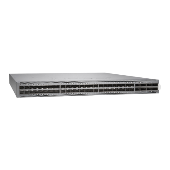
QFX5120 Switch Quick Start Guide
The QFX5120 delivers low latency, native 25GbE, rich Layer 2 and Layer 3 features, VXLAN overlay support, and 100GbE uplinks,
making it the ideal switch for access and top-of-rack deployments. Featuring Layer 3 gateway capabilities for bridging between
virtualized and bare-metal servers, the QFX5120 is designed for extremely agile data centers that demand support for overlay/
underlay network architectures. The high-density 10GbE, 25GbE, 40GbE, and 100GbE ports also make the QFX5120 ideally suited
for deployment as leaf-and-spine and leaf topologies. Featuring 48 wire-speed 10GbE/25GbE small form-factor pluggable and
pluggable plus transceiver (SFP/SFP+/SFP28) ports and 8 wire-speed 40GbE/100GbE quad SFP+ transceiver (QSFP+/QSP28)
ports in a compact 1U platform, the QFX5120 provides the flexibility to support mixed 1GbE, 10GbE, 25GbE, 40GbE, and 100GbE
environments.
Starting with Junos OS Release 18.3R1, the QFX5120-48Y switch is available as a fixed-configuration switch with the following
built-in ports:
Forty-eight 25-Gigabit Ethernet ports that can operate at 1-Gbps, 10-Gbps, or 25-Gbps speed and support SFP, SFP+, or SFP28
transceivers.
Eight 100-Gigabit Ethernet ports that can operate at 40-Gbps or 100-Gbps speed and support QSFP+ or QSFP28 transceivers.
When these ports operate at 40-Gbps speed, you can configure four 10-Gbps interfaces and connect breakout cables, increasing
the total number of supported 10-Gbps ports to 80. When these ports operate at 100-Gbps speed, you can configure four
25-Gbps interfaces and connect breakout cables, increasing the total number of supported 25-Gbps ports to 80.
A total of four models are available: two featuring AC power supplies and front-to-back or back-to-front airflow and two featuring
DC power supplies and front-to-back or back-to-front airflow.
Tools and Parts Required for Installation
NOTE:
See the complete documentation at
To mount a Juniper Networks QFX5120 Ethernet switch on a rack, you need:
Two front-mounting brackets and twelve screws to secure the brackets to the chassis—provided
Two rear-mounting brackets—provided
Screws to secure the chassis to the rack—not provided
Phillips (+) screwdriver, number 2—not provided
Electrostatic discharge (ESD) grounding strap—not provided
Fan module—preinstalled
https://www.juniper.net/documentation/product/en_US/qfx5120
.
Advertisement
Table of Contents

Related Manuals for Juniper QFX5120


Summary of Contents for Juniper QFX5120
- Page 1 QFX5120 Switch Quick Start Guide The QFX5120 delivers low latency, native 25GbE, rich Layer 2 and Layer 3 features, VXLAN overlay support, and 100GbE uplinks, making it the ideal switch for access and top-of-rack deployments. Featuring Layer 3 gateway capabilities for bridging between virtualized and bare-metal servers, the QFX5120 is designed for extremely agile data centers that demand support for overlay/ underlay network architectures.
-
Page 2: Part 1: Install A Power Supply
Register product serial numbers on the Juniper Networks website and update the installation base data if there is any addition or change to the installation base or if the installation base is moved. Juniper Networks will not be held accountable for not meeting the hardware replacement service-level agreement for products that do not have registered serial numbers or accurate installation base data. -
Page 3: Part 2: Install A Fan Module
Figure 1 Figure Figure 1: Installing an AC Power Supply in QFX5120 Switches Figure 2: Installing a DC Power Supply in QFX5120 Switches If the power supply slot has a cover panel on it, use your fingers to hold and gently pull the cover panel outward to remove the cover panel. - Page 4 Part 3: Mount the Switch on Four Posts of a Rack You can mount a QFX5120 switch on four posts of a 19-in. rack or an ETSI rack. This guide describes the procedure to mount the switch on a 19-in. rack.
-
Page 5: Part 4: Connect Power To The Switch
QFX5120 Switch Quick Start Guide Figure 5: Securing the Switch to the Rack On the rear of the switch chassis, slide the rear-mounting brackets into the front-mounting brackets on either side of the chassis until the rear-mounting brackets contact the rack rails (see... - Page 6 To connect power to a switch powered by AC power supply (see Figure Figure 7: Connecting Power to a QFX5120 Switch Powered by AC Power Supply Push the end of the retainer strip into the hole next to the inlet on the power supply faceplate until it snaps into place.
-
Page 7: Part 5: Perform Initial Configuration
To connect power to a switch powered by DC power supply (see Figure Figure 8: Connecting Power to a QFX5120 Switch Powered by DC Power Supply The DC power supply has terminals labeled V-, V–, V+, and V+ for connecting DC power source cables labeled positive (+) and negative (–). - Page 8 0 family inet address address/prefix-length root@# NOTE: The management ports (C0) and (C1)are located on the rear panel of QFX5120. (Optional) Configure the static routes to remote prefixes with access to the management port. [edit] Copyright © 2018, Juniper Networks, Inc.
-
Page 9: Safety Warnings Summary
Enter yes to commit the configuration. The configuration is committed as the active configuration for the switch. You can now log in by using the CLI and continue configuring the switch. Safety Warnings Summary This is a summary of safety warnings. For a complete list of warnings, including translations, see the QFX5120 documentation at https://www.juniper.net/documentation/product/en_US/qfx5120 WARNING: Failure to observe these safety warnings can result in personal injury or death. -
Page 10: Contacting Juniper Networks
Juniper Networks, the Juniper Networks logo, Juniper, and Junos are registered trademarks of Juniper Networks, Inc. in the United States and other countries. All other trademarks, service marks, registered marks, or registered service marks are the property of their respective owners. Juniper Networks assumes no responsibility for any inaccuracies in this document.