
Related Manuals for Juniper QFX5110


Summary of Contents for Juniper QFX5110
- Page 1 QFX5110 Switch Hardware Guide Modified: 2017-08-28 Copyright © 2017, Juniper Networks, Inc.
- Page 2 END USER LICENSE AGREEMENT The Juniper Networks product that is the subject of this technical documentation consists of (or is intended for use with) Juniper Networks software. Use of such software is subject to the terms and conditions of the End User License Agreement (“EULA”) posted at http://www.juniper.net/support/eula/.
-
Page 3: Table Of Contents
QFX5110 Field-Replaceable Units ........15 QFX5110 Access Port and Uplink Port LEDs ....... 16 QFX5110 Management Panel . - Page 4 QFX5110 Cooling System and Airflow ........
- Page 5 Connecting Earth Ground to a QFX5110 ....... . . 84...
- Page 6 QFX5110 Chassis Lifting Guidelines ........
- Page 7 United States ..........200 Nonregulatory Environmental Standards ......200 Copyright © 2017, Juniper Networks, Inc.
- Page 8 QFX5110 Switch Hardware Guide viii Copyright © 2017, Juniper Networks, Inc.
- Page 9 Figure 16: Power Supply Handle Detail ........34 Figure 17: DC Power Supply for the QFX5110 ......35 Figure 18: DC Power Supply Faceplate on a QFX5110 .
- Page 10 Replacing Cooling System Components ......105 Figure 40: Installing a Fan Module in a QFX5110 ......106 Figure 41: Removing a Fan Module from a QFX5110 .
- Page 11 QFX5110-48S ........
- Page 12 QFX5110 Switch Hardware Guide Copyright © 2017, Juniper Networks, Inc.
-
Page 13: List Of Tables
Table 13: Fan Tray LED in a QFX5110 Switch ......30... - Page 14 QFX5110 Switch Hardware Guide Table 26: DC Power Specifications for QFX5110 ......59 Chapter 7 Transceiver and Cable Specifications .
-
Page 15: About The Documentation
® To obtain the most current version of all Juniper Networks technical documentation, see the product documentation page on the Juniper Networks website at http://www.juniper.net/techpubs/ If the information in the latest release notes differs from the information in the documentation, follow the product Release Notes. -
Page 16: Table 1: Notice Icons
RFC 1997, BGP Communities Attribute Italic text like this Represents variables (options for which Configure the machine’s domain name: you substitute a value) in commands or [edit] configuration statements. root@# set system domain-name domain-name Copyright © 2017, Juniper Networks, Inc. -
Page 17: Documentation Feedback
We encourage you to provide feedback, comments, and suggestions so that we can improve the documentation. You can provide feedback by using either of the following methods: Online feedback rating system—On any page of the Juniper Networks TechLibrary site , simply click the stars to rate the content, http://www.juniper.net/techpubs/index.html and use the pop-up form to provide us with information about your experience. -
Page 18: Requesting Technical Support
7 days a week, 365 days a year. Self-Help Online Tools and Resources For quick and easy problem resolution, Juniper Networks has designed an online self-service portal called the Customer Support Center (CSC) that provides you with the following features: Find CSC offerings: http://www.juniper.net/customers/support/... - Page 19 About the Documentation For international or direct-dial options in countries without toll-free numbers, see http://www.juniper.net/support/requesting-support.html Copyright © 2017, Juniper Networks, Inc.
- Page 20 QFX5110 Switch Hardware Guide Copyright © 2017, Juniper Networks, Inc.
-
Page 21: Overview
PART 1 Overview System Overview on page 3 Chassis Components and Descriptions on page 9 Cooling System and Airflow on page 25 Power Supplies on page 33 Copyright © 2017, Juniper Networks, Inc. -
Page 22: Lbs (10.43 Kg) With
QFX5110 Switch Hardware Guide Copyright © 2017, Juniper Networks, Inc. -
Page 23: System Overview
System Software on page 6 QFX5110 Models Overview The QFX5110 line of switches offers two compact 1 U models that are ideal for top-of-rack, QFX Virtual Chassis, or Virtual Chassis Fabric (VCF) deployments, the 48-port QFX5110-48S and the 32-port QFX5110-32Q. Performance of the control plane running on all the QFX5110 switches is enhanced by the 1.8-Ghz quad-core Intel CPU with 16 GB... - Page 24 You can configure up to a total of 20 QFX5110 or QFX5100 devices in a VCF. Out of the 20 total devices, you can configure a maximum of 4 spine devices. You...
-
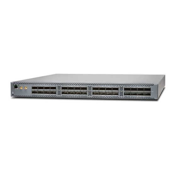
Page 25: Qfx5110-48S Hardware
The four QSFP28 ports can be used as either access ports or as uplinks. The QFX5110-48S provides an aggregate throughput of 960 Gbps. The QFX5110-48S has a 1 U form factor and comes standard with redundant fans and redundant power supplies. -
Page 26: System Software
Figure 2: QFX5110-32Q Port Panel System Software QFX Series devices use the Junos operating system (OS), which is installed on a QFX5110 switch’s 64-GB internal solid-state flash drive. The same Junos OS code base that runs on QFX5110 switches also runs on all Juniper Networks EX Series switches, and M Series, MX Series, and T Series routers. -
Page 27: Qfx5110 Hardware Models
Virtual Chassis Fabric Overview QFX5110 Hardware Models The QFX5110 switches have 32 or 48 port configurations. Both switches are available with either AC or DC power supply and with either airflow-in or airflow-out cooling. All models of the QFX5110, except the QFX5110-32Q_CHAS, ship with two power supplies and five fans installed by default. -
Page 28: Functionality
Cooling system—All QFX5110 switches, except the QFX5110-32Q-CHAS, ship with five fan modules installed. If a fan module fails and is unable to keep the QFX5110 within the desired temperature thresholds, chassis alarms occur and the QFX5110 can shut down. -
Page 29: Chassis Components And Descriptions
Installing and Removing QFX5110 Hardware Components on page 123 QFX5110-48S Port Panel The port panel of the QFX5110-48S is primarily comprised of 48 small form-factor pluggable plus (SFP+) and 4 quad small form-factor pluggable solution (QSFP28) ports. Copyright © 2017, Juniper Networks, Inc. -
Page 30: Switch Overview
Channelizing Interfaces on page 11 Virtual Chassis and Virtual Chassis Fabric on page 11 Switch Overview The port panel of the QFX5110-48S supports 48 logical 10-GbE ports when operating as a standalone switch. These data ports ( through ) support either 1-Gbps or 10-Gbps SFP+ transceivers. -
Page 31: Channelizing Interfaces
QFX5110 switches in a ring topology. To connect a QFX5110 switch as a spine or leaf device in a Virtual Chassis Fabric (VCF), you need a pair of dedicated ports and cables that link each spine device and leaf device... -
Page 32: Qfx5110-32Q Port Panel
Channelizing Interfaces on page 13 Virtual Chassis and Virtual Chassis Fabric on page 15 Switch Overview The ports on the QFX5110-32Q support 40-Gbps or 100-Gbps speeds natively. Of the 28 QSFP+ ports, through also support 10-Gbps speeds when the ports are configured as Flexi-pic and channelized using QSFP+ to SFP+ DAC breakout (DACBO) cables. -
Page 33: Switch Ports
Starting with Junos OS Release 17.3R1, the ports auto-sense the transceiver and set the port speed to match. The Flexible PIC Concentrator (FPC) does not reboot when the system mode changes. The following system modes are available on the QFX5110-32Q: Default mode Copyright © 2017, Juniper Networks, Inc. -
Page 34: Table 5: Default Behavior Of 100 Gigabit Ethernet Ports
If you have existing ports that are channelized in Flexi-pic mode, remove the channelization from the interface before changing the system mode. Changing the Flexi-pic mode to the default mode with channelized Copyright © 2017, Juniper Networks, Inc. -
Page 35: Virtual Chassis And Virtual Chassis Fabric
QFX5110 switches in a ring topology. To connect a QFX5110 switch as a spine or leaf device in a Virtual Chassis Fabric (VCF), you need a pair of dedicated ports and cables that link each spine device and leaf device in the VCF. -
Page 36: Qfx5110 Access Port And Uplink Port Leds
Installing a Transceiver in a QFX Series Device on page 113 Removing a Transceiver from a QFX Series Device QFX5110 Access Port and Uplink Port LEDs The Link/Activity LED configuration for QFX5110 uses bi-colored LEDs. The link LED indicates link activity or a fault. See Table 7 on page... -
Page 37: Table 7: Qfx5110-48 Access Port And Uplink Led Locations
The first LED indicates link presence and activity, while the remaining LEDs indicate status. Table 9 on page 17 describes how to interpret the Link/Activity QSFP28 port LEDs, counting from the left-most position. Table 9: Network Port LEDs on QSFP28 Ports on a QFX5110 Position Color State Description 1–4... -
Page 38: Qfx5110 Management Panel
Installing a Transceiver in a QFX Series Device on page 113 Connecting a Fiber-Optic Cable to a QFX Series Device QFX5110 Management Panel The management panel of the QFX5110 is found on the field-replaceable unit (FRU) end of the switch, as shown in Figure 5 on page 18. -
Page 39: Figure 6: Management Panel Components On Qfx5110
C0–Use the RJ-45 connectors for 10/100/1000BASE-T or to cable a virtual management Ethernet (VME) interface for spine members in a VCF. See Connecting a QFX5110 to a Network for Out-of-Band Management. NOTE: If both C0 ports are cabled, the copper C0 has priority over the fiber C0. -
Page 40: Qfx5110 Management Port Leds
QFX5110 Switch Hardware Guide QFX5110 Management Port LEDs The management ports (labeled for 10/100/1000BASE-T and 10/100/1000BASE-T and SFP 1000BASE-X connections) on a QFX5110 switch have two LEDs that indicate link status and link activity (see Figure 7 on page 20). The left LED indicates status;... -
Page 41: Qfx5110 Chassis Status Leds
Chapter 2: Chassis Components and Descriptions QFX5110 Chassis Status LEDs The QFX5110 switch series has four status LEDs on the FRU side of the chassis, next to the management ports (see Figure 8 on page 21). Figure 8: Chassis Status LEDs on a QFX5110 Switch 1—... -
Page 42: Table 11: Chassis Status Leds On A Qfx5110 Switch
QFX5110 Switch Hardware Guide Table 11: Chassis Status LEDs on a QFX5110 Switch Name Color State Description ALM–Alarm or beacon Unlit The switch is halted or there is no alarm. On steadily A major hardware fault has occurred, such as a temperature alarm or power failure, and the switch has halted. - Page 43 Chapter 2: Chassis Components and Descriptions Table 11: Chassis Status LEDs on a QFX5110 Switch (continued) Name Color State Description ID–Identification Unlit The beacon feature is not enabled on the switch. This feature is enabled using the command. request chassis beacon...
-
Page 44: Cispr
QFX5110 Switch Hardware Guide Copyright © 2017, Juniper Networks, Inc. -
Page 45: Cooling System And Airflow
QFX5110 Fan Module LED on page 30 QFX5110 Cooling System and Airflow The cooling system in an QFX5110 device consists of five fan modules and a single fan in each power supply. The switch can be set up to work in one of two airflow directions: Airflow In–Air comes into the switch through the vents in the field-replaceable units... -
Page 46: Figure 9: Qfx5110 Fan Module
Table 12 on page 26 lists the available fan module product SKUs and the direction of airflow in them. Table 12: Fan Modules in the QFX5110 Label on the Color of Fan Direction of Airflow in Fan Module... -
Page 47: Cooling System And Airflow
Chapter 3: Cooling System and Airflow Table 12: Fan Modules in the QFX5110 (continued) QFX5110-32Q-FANAFI Figure 12 on page 28 Juniper Azure FRU-to-port, that is, air You must install AIR IN Blue comes in from the end of only power the switch with the fans;... -
Page 48: Figure 11: Air Out Airflow Through The Qfx5110-48S
QFX5110 Switch Hardware Guide Figure 11: Air Out Airflow Through the QFX5110-48S Figure 12: Air In Airflow Through the QFX5110-32Q Copyright © 2017, Juniper Networks, Inc. -
Page 49: Switch
Chapter 3: Cooling System and Airflow Figure 13: Air Out Airflow Through the QFX5110-32Q Do Not Install Components with Different Airflow or Wattage in the Switch Do not mix power supplies with different airflow. If the power supplies are color-coded, ensure they are either all azure blue for airflow in models or all gold for airflow out models. -
Page 50: Qfx5110 Fan Module Led
QFX5110 Switch Hardware Guide However, if you need to convert a QFX5110 to have a different airflow, you can change the airflow pattern. To convert an product SKU to an product SKU or an AIR IN AIR OUT product SKU to a... - Page 51 If the temperature inside the chassis rises above the threshold temperature, the system shuts down automatically. Related Installing a Fan Module in a QFX5110 on page 105 Documentation Removing a Fan Module from a QFX5110 on page 106...
- Page 52 QFX5110 Switch Hardware Guide Copyright © 2017, Juniper Networks, Inc.
-
Page 53: Power Supplies
Figure 15 on page 34 for an example of a QFX5110 AC power supply. Each power supply is a hot-removable and hot-insertable field-replaceable unit (FRU) when the second power supply is installed and running. You can install replacement power supplies in the two slots next to the fan modules without powering off the switch or disrupting the switching function. -
Page 54: Figure 15: Ac Power Supply In Qfx5110 Switches
QFX5110 Switch Hardware Guide Figure 15: AC Power Supply in QFX5110 Switches 1— Handle 3— AC appliance inlet 2— Power cord retainer 4— Security latch The power supply provides FRU-to-port or port-to-FRU airflow depending on the product SKU you purchase. On legacy switches, or switches with an LCD, this airflow is called back-to-front and front-to-back. -
Page 55: Qfx5110 Dc Power Supply
You can install replacement power supplies in the two slots next to the fan modules without powering off the switch or disrupting the switching function. The DC power supply in QFX5110 is 650 W with dual feeds for power resiliency. Figure 17: DC Power Supply for the QFX5110 1—... -
Page 56: Figure 18: Dc Power Supply Faceplate On A Qfx5110
QFX5110 Switch Hardware Guide Figure 18: DC Power Supply Faceplate on a QFX5110 1— Shunt negative input terminals (-48V) 5— ESD grounding point 2— Shunt positive input terminals (+RTN) 6— Fault LED 3— Terminal block 7— Output LED 4— Security latch 8—... -
Page 57: Qfx5110 Ac Power Supply Leds
Connecting DC Power to a QFX5110 on page 87 QFX5110 AC Power Supply LEDs Figure 19 on page 37 shows the location of the LEDs on the power supply. Figure 19: AC Power Supply LEDs on a QFX5110 Switch AC OK DC OK Fault Table 16 on page 37 describes the LEDs on the AC power supplies. -
Page 58: Qfx5110 Dc Power Supply Leds
QFX5110 Switch Hardware Guide QFX5110 DC Power Supply LEDs Figure 20 on page 38 shows the location of the LEDs on the DC power supply. Figure 20: DC Power Supply Faceplate on a QFX5110 Switch 1— Input LED 3— Fault LED 2—Output LED... - Page 59 Chapter 4: Power Supplies Related QFX5110 DC Power Supply on page 35 Documentation QFX5110 DC Power Specifications on page 59 Connecting DC Power to a QFX5110 on page 87 Copyright © 2017, Juniper Networks, Inc.
- Page 60 QFX5110 Switch Hardware Guide Copyright © 2017, Juniper Networks, Inc.
-
Page 61: Site Planning, Preparation, And Specifications
PART 2 Site Planning, Preparation, and Specifications Preparation Overview on page 43 Power Specifications and Requirements on page 57 Transceiver and Cable Specifications on page 61 Pinout Specifications on page 69 Copyright © 2017, Juniper Networks, Inc. - Page 62 QFX5110 Switch Hardware Guide Copyright © 2017, Juniper Networks, Inc.
-
Page 63: Preparation Overview
Planning a Virtual Chassis Deployment using QFX Devices on page 48 Planning a Virtual Chassis Fabric Deployment on page 51 QFX5110 Rack Requirements on page 53 QFX5110 Clearance Requirements for Airflow and Hardware Maintenance on page 55 QFX5110 Site Preparation Checklist The checklist in... -
Page 64: Qfx5110 Environmental Requirements And Specifications
General Site Guidelines on page 45 Installing and Connecting a QFX5110 on page 75 Mounting a QFX5110 in a Rack on page 77 QFX5110 Environmental Requirements and Specifications The switch must be installed in a rack or cabinet. It must be housed in a dry, clean, well-ventilated, and temperature-controlled environment. -
Page 65: General Site Guidelines
Articles 110-16, 110-17, and 110-18 of the National Electrical Code, ANSI/NFPA 70. Related QFX5110 Clearance Requirements for Airflow and Hardware Maintenance on page 55 Documentation Installing and Connecting a QFX5110 on page 75... -
Page 66: Site Electrical Wiring Guidelines
Electrical hazards as a result of power surges conducted over the lines into the equipment Related General Safety Guidelines and Warnings on page 153 Documentation General Electrical Safety Guidelines and Warnings on page 181 Prevention of Electrostatic Discharge Damage on page 182 Copyright © 2017, Juniper Networks, Inc. -
Page 67: Virtual Chassis Fabric Hardware Overview
QFX5100-24Q and the QFX5100-48S are available in a VCF, use the QFX5100-24Q as the spine. In a QFX5110 VCF, the optimum configuration comprises only QFX5110 models. When multiple models of QFX5110 are in a VCF, use the QFX5110-32Q as the spine. All QFX5110 VCF configurations are considered homogeneous. Related... -
Page 68: Planning A Virtual Chassis Deployment Using Qfx Devices
VCPs. This topic covers: Valid Configurations for a QFX Virtual Chassis on page 48 Valid Configurations for a QFX5110 Virtual Chassis on page 49 VC Deployment Checklist on page 49 Valid Configurations for a QFX Virtual Chassis Valid configurations are: All QFX5100 members (homogenous)–Supported QFX5100 models are:... -
Page 69: Valid Configurations For A Qfx5110 Virtual Chassis
Valid configurations are: All QFX5110 members (homogenous)–Supported QFX5110 models are: QFX5110-32Q QFX5110-48S A mixture of QFX5110 and QFX5100 members (heterogeneous)–use the QFX5110 models as the master RE and backup RE. Use the following QFX5100 switches in the line card role: QFX5100-24Q... - Page 70 Item or Task For More Information Performed By Date Calculate the power consumption “QFX5110 AC Power Specifications” on page 57 and requirements. AC Power Specifications for a QFX5100 Device AC Power Specifications for a QFX3600 or QFX3600-I Device AC Power Specifications for a QFX3500 Device...
-
Page 71: Planning A Virtual Chassis Fabric Deployment
64 Plan the cable routing and management. Related QFX5110 Site Preparation Checklist on page 43 Documentation Site Preparation Checklist for a QFX5100 Device Site Preparation Checklist for a QFX3600 or QFX3600-I Device Site Preparation Checklist for a QFX3500 Device... - Page 72 Measure the distance between external power sources and switch installation site. Calculate the power consumption and “QFX5110 AC Power Specifications” on page 57 requirements. AC Power Specifications for a QFX5100 Device AC Power Specifications for a QFX3600 or QFX3600-I Device...
-
Page 73: Qfx5110 Rack Requirements
Site Preparation Checklist for a QFX3600 or QFX3600-I Device Site Preparation Checklist for a QFX3500 Device Site Preparation Checklist for EX4300 Switches QFX5110 Rack Requirements QFX5110 switches are designed to be installed on four-post racks. Rack requirements consist of: Rack type Copyright © 2017, Juniper Networks, Inc. -
Page 74: Table 23: Rack Requirements For The Qfx5110
QFX5110 Chassis Physical Specifications on page 9 Documentation Rack-Mounting and Cabinet-Mounting Warnings on page 164 QFX5110 Clearance Requirements for Airflow and Hardware Maintenance on page 55 Mounting a QFX5110 in a Rack on page 77 Copyright © 2017, Juniper Networks, Inc. -
Page 75: Qfx5110 Clearance Requirements For Airflow And Hardware Maintenance
Leave at least 24 in. (61 cm) both in front of and behind the QFX5110. For service personnel to remove and install hardware components, you must leave adequate space at the front and back of the switch. - Page 76 QFX5110 Switch Hardware Guide Copyright © 2017, Juniper Networks, Inc.
-
Page 77: Power Specifications And Requirements
QFX5110 AC Power Specifications Table 24 on page 57 describes the AC power specifications for QFX5110 switches. The typical and maximum power consumption values are calculated using small form-factor plus (SFP+) direct attach copper (DAC) cables on all network ports and all 100GBASE-SR4 transceivers in the uplink ports. -
Page 78: Qfx5110 Ac Power Cord Specifications
250 VAC, 10 A, 60 Hz KSC 8305 CG_CBL-C13-06-KR Switzerland 250 VAC, 10 A, 50 Hz SEV 1011–2009 CG_CBL-C13-06-SZ United Kingdom 250 VAC, 10 A, 50 Hz BS 1363 CG_CBL-C13-06--UK Related QFX5110 AC Power Supply on page 33 Documentation Copyright © 2017, Juniper Networks, Inc. -
Page 79: Qfx5110 Dc Power Specifications
QFX5110 AC Power Specifications on page 57 QFX5110 DC Power Specifications Table 26 on page 59 describes the QFX5110 DC power specifications. The typical and maximum power consumption values are calculated using dummy transceivers on all ports. Traffic is run at 25° C ambient. - Page 80 QFX5110 Switch Hardware Guide Copyright © 2017, Juniper Networks, Inc.
-
Page 81: Transceiver And Cable Specifications
Calculating the Fiber-Optic Cable Power Budget for a QFX Series Device on page 66 Calculating the Fiber-Optic Cable Power Margin for a QFX Series Device on page 66 Determining Transceiver Support for the QFX5110 The port panel of the QFX5110-48S supports 48 logical 10-Gigabit Ethernet ports. These data ports ( through ) support either 1-Gigabit small form-factor pluggable (SFP) or 10-Gigabit Ethernet Ethernet small form-factor pluggable plus (SFP+) transceivers. -
Page 82: Cable Specifications For Qsfp+ And Qsfp28 Transceivers
QFX5110 Switch Hardware Guide replace it with an equivalent Juniper Networks optic or cable that is qualified for the device. Related QFX5110-48S Port Panel on page 9 Documentation Cable Specifications for QSFP+ and QSFP28 Transceivers The 40-Gigabit Ethernet QSFP+ and 100-Gigabit Ethernet QSFP28 transceivers that are used in QFX Series and EX4600 switches use 12-ribbon multimode fiber crossover cables with female MPO/UPC connectors. -
Page 83: Table 28: Qsfp+ Mpo Fiber-Optic Crossover Cable Pinouts
Documentation Determining Interface Support for the QFX3600 Device Determining Interface Support for the QFX5100 Device Determining Transceiver Support for the QFX5110 on page 61 Determining QFX5200 Optical Interface Support Determining QFX10000 Optical Transceiver and Cable Support Copyright © 2017, Juniper Networks, Inc. -
Page 84: Signal Loss In Multimode And Single-Mode Fiber-Optic Cables
Management Port Connector Pinouts for the QFX Series Connecting a QFX Series Device to a Management Console Connecting a QFX5110 to a Network for Out-of-Band Management Understanding QFX Series Fiber-Optic Cable Signal Loss, Attenuation, and Dispersion To determine the power budget and power margin needed for fiber-optic connections, you need to understand how signal loss, attenuation, and dispersion affect transmission. -
Page 85: Attenuation And Dispersion In Fiber-Optic Cable
The optical power budget must allow for the sum of component attenuation, power penalties (including those from dispersion), and a safety margin for unexpected losses. Related Calculating the Fiber-Optic Cable Power Budget for a QFX Series Device on page 66 Documentation Copyright © 2017, Juniper Networks, Inc. -
Page 86: Calculating The Fiber-Optic Cable Power Budget For A Qfx Series Device
) greater than zero indicates that the power budget is sufficient to operate the receiver and that it does not exceed the maximum receiver input power. This means the link will work. A (P ) that is zero or negative indicates insufficient power Copyright © 2017, Juniper Networks, Inc. -
Page 87: Table 30: Estimated Values For Factors Causing Link Loss
1 dBm (CRM) NOTE: For information about the actual amount of signal loss caused by equipment and other factors, see your vendor documentation for that equipment. Calculate the (P ) by subtracting (LL) from (P Copyright © 2017, Juniper Networks, Inc. - Page 88 Also, the power margin value does not exceed the maximum receiver input power. Refer to the specifications for your receiver to find the maximum receiver input power. Related Understanding QFX Series Fiber-Optic Cable Signal Loss, Attenuation, and Dispersion Documentation on page 64 Copyright © 2017, Juniper Networks, Inc.
-
Page 89: Pinout Specifications
RJ-45 Management Port Connector Pinout Information on page 71 USB Port Specifications for the QFX Series The following Juniper Networks USB flash drives have been tested and are officially supported for the USB port in the QFX Series: RE-USB-1G-S—1-gigabyte (GB) USB flash drive (except QFX3100 Director device) RE-USB-2G-S—2-GB USB flash drive (except QFX3100 Director device) -
Page 90: Console Port Connector Pinout Information
Performing a Recovery Installation Using an Emergency Boot Device Console Port Connector Pinout Information The console port on a Juniper Networks device is an RS-232 serial interface that uses an RJ-45 connector to connect to a console management device. The default baud rate for the console port is 9600 baud. -
Page 91: Rj-45 Management Port Connector Pinout Information
Chapter 8: Pinout Specifications RJ-45 Management Port Connector Pinout Information Table 32 on page 71 provides the pinout information for the RJ-45 connector for the management port on Juniper Networks devices. Table 32: RJ-45 Management Port Connector Pinout Information Signal Description... - Page 92 QFX5110 Switch Hardware Guide Copyright © 2017, Juniper Networks, Inc.
-
Page 93: Initial Installation And Configuration
Initial Installation and Configuration Unpacking and Mounting the Switch on page 75 Connecting the Switch to Power on page 83 Connecting the Switch to the Network on page 93 Performing Initial Configuration on page 99 Copyright © 2017, Juniper Networks, Inc. - Page 94 QFX5110 Switch Hardware Guide Copyright © 2017, Juniper Networks, Inc.
-
Page 95: Unpacking And Mounting The Switch
Unpacking and Mounting the Switch Installing and Connecting a QFX5110 on page 75 Unpacking a QFX5110 on page 76 Mounting a QFX5110 in a Rack on page 77 Virtual Chassis Fabric Installation Overview on page 80 Installing and Connecting a QFX5110 You can mount a QFX5110: Flush with the front of a 19-in. -
Page 96: Unpacking A Qfx5110
Unpacking a QFX5110 The QFX5110 is a rigid sheet-metal structure that houses the hardware components. A QFX5110 is shipped in a cardboard carton, secured with foam packing material. The carton also contains an accessory box and quick start instructions. CAUTION: The QFX5110 is maximally protected inside the shipping carton. -
Page 97: Mounting A Qfx5110 In A Rack
Installing and Connecting a QFX5110 on page 75 Mounting a QFX5110 in a Rack You can mount a QFX5110 on a four-post 19-in. rack using the mounting kit provided with the switch. This kit contains two front-mounting rails with two matching rear-mounting blades. -
Page 98: Procedure
If you are installing the QFX5110 above 60 in. (152.4 cm) from the floor, you can remove the power supplies and fan modules to minimize the weight before attempting to install the switch. -
Page 99: Figure 22: Attaching Mounting Rails To The Qfx5110-48S
Figure 23 on page 79 to see the proper alignment for the QFX5110. Figure 22: Attaching Mounting Rails to the QFX5110-48S Figure 23: Attaching Mounting Rails to the QFX5110-32Q Attach the mounting rail to the switch using the mounting screws. Tighten the screws. -
Page 100: Virtual Chassis Fabric Installation Overview
Related Rack-Mounting and Cabinet-Mounting Warnings on page 164 Documentation Connecting Earth Ground to a QFX5110 on page 84 Connecting AC Power to a QFX5110 on page 85 Virtual Chassis Fabric Installation Overview For best results, ensure you review and understand the Virtual Chassis Fabric (VCF) configuration options. - Page 101 Cable the ports that you will use as VCPs. For cabling examples, see “Connecting a QFX5110 Device in a QFX5110 Virtual Chassis Fabric” on page 96, Connecting a QFX5100 Device in a Virtual Chassis Fabric, Connecting a QFX3500 or QFX3600 Switch in a Virtual Chassis Fabric, and Connecting EX Series Switches in a Virtual Chassis Fabric.
- Page 102 Chassis ports (VCP) are automatically configured. If you configure the devices as nonprovisioned, you must manually configure the VCPs. Related Understanding Virtual Chassis Fabric Configuration Documentation Virtual Chassis Fabric Hardware Overview on page 47 Adding a Device to a Virtual Chassis Fabric Copyright © 2017, Juniper Networks, Inc.
-
Page 103: Connecting The Switch To Power
CHAPTER 10 Connecting the Switch to Power Connecting Earth Ground to a QFX5110 on page 84 Connecting AC Power to a QFX5110 on page 85 Connecting DC Power to a QFX5110 on page 87 Copyright © 2017, Juniper Networks, Inc. -
Page 104: Connecting Earth Ground To A Qfx5110
Connecting Earth Ground to a QFX5110 To meet safety and electromagnetic interference (EMI) requirements and to ensure proper operation, you must connect the QFX5110 to earth ground before you connect it to power. For installations that require a separate grounding conductor to the chassis, you must attach a protective earthing terminal bracket. -
Page 105: Connecting Ac Power To A Qfx5110
Connecting DC Power to a QFX5110 on page 87 Connecting AC Power to a QFX5110 The QFX5110 is shipped with two 650 W power supplies pre-installed. Each power supply is a hot-removable and hot-insertable field-replaceable unit (FRU) when the second power supply is installed and running. - Page 106 33). Install the power supply in the chassis. For instructions on installing a power supply in a QFX5110, see “Installing a Power Supply in a QFX5110” on page 109. NOTE: Each power supply must be connected to a dedicated power source outlet.
-
Page 107: Connecting Dc Power To A Qfx5110
QFX5110 AC Power Supply LEDs on page 37 Connecting DC Power to a QFX5110 The QFX5110 is shipped from the factory with two 650 W power supplies. Each power supply is a hot-removable and hot-insertable field-replaceable unit (FRU) when the second power supply is installed and running. - Page 108 WARNING: A DC-powered QFX5110 is intended for installation only in a restricted access location. NOTE: The battery returns of the DC power supply must be connected as an isolated DC return (DC-I).
- Page 109 Figure 30 on page 91). The QFX5110 is designed to operate with a DC power supply that has a single, non-redundant, feed input. For source redundancy, two DC power supplies must be installed in the QFX5110; connect source (A) to one power supply and connect source...
-
Page 110: Figure 29: Dc Power Supply Faceplate For A Qfx5110
Tighten the screws on the power supply terminals until snug using the screwdriver. Do not overtighten; apply between 5 in-lb (0.56 Nm) and 6 in-lb (0.68 Nm) of torque to the screws. Figure 29: DC Power Supply Faceplate for a QFX5110 1— Shunt negative input terminals (+RTN) 5—... -
Page 111: Figure 30: Securing Ring Lugs To The Terminals On The Qfx5110 Dc Power
Do not connect the terminals to different sources. Figure 30: Securing Ring Lugs to the Terminals on the QFX5110 DC Power Supply Replace the terminal block cover. - Page 112 QFX5110 Switch Hardware Guide Copyright © 2017, Juniper Networks, Inc.
-
Page 113: Connecting The Switch To The Network
Connecting a Device to a Management Console by Using an RJ-45 Connector on page 94 Connecting QFX5110 and QFX5100 Members in a QFX5110 Virtual Chassis on page 95 Connecting a QFX5110 Device in a QFX5110 Virtual Chassis Fabric on page 96 Connecting a Device to a Network for Out-of-Band Management You can monitor and manage these devices by using a dedicated management channel. -
Page 114: Figure 32: Connecting A Device To A Network For Out-Of-Band Management
PC directly to the device, use a combination of the RJ-45 to DB-9 female adapter supplied with the device and a USB to DB-9 male adapter. You must provide the USB to DB-9 male adapter. Copyright © 2017, Juniper Networks, Inc. -
Page 115: Connecting Qfx5110 And Qfx5100 Members In A Qfx5110 Virtual Chassis
Connecting QFX5110 and QFX5100 Members in a QFX5110 Virtual Chassis QFX5110 Virtual Chassis are cabled in a ring topology. Each Virtual Chassis has a master, a backup, and up to 8 additional switches participating as members of the Virtual Chassis. -
Page 116: Connecting A Qfx5110 Device In A Qfx5110 Virtual Chassis Fabric
In the spine-and-leaf architecture, each spine device is interconnected to each leaf device. QFX5110 VCFs support a maximum of 20 members in a VCF. Use QFX5110-32Q as either the spine or as a leaf device. Use QFX5110-48S, QFX5100-24Q, QFX5100-48S, or QFX5100-96S models only as leaf devices. -
Page 117: Figure 38: All Qfx5110 Vcf
Figure 38 on page 97 shows cabling for a QFX5110 VCF with two QFX5110-32Q spine devices connected to four QFX5110-48S as leaf devices, all using all QSFP28 ports as VCPs.Figure 39 on page 98 shows the cabling for a QFX5110 VCF using QFX5110-32Q as spines and QFX5100-24Q leaf devices. -
Page 118: Figure 39: Qfx5110 Vcf With Qfx5100-24Q Leaf Devices
QFX5110 Switch Hardware Guide Figure 39: QFX5110 VCF with QFX5100-24Q Leaf Devices Related Virtual Chassis Fabric Hardware Overview on page 47 Documentation Planning a Virtual Chassis Fabric Deployment on page 51 Copyright © 2017, Juniper Networks, Inc. -
Page 119: Performing Initial Configuration
Performing Initial Configuration Configuring a QFX5110 on page 99 Configuring a QFX5110 You must perform the initial configuration of the QFX5110 through the console port using the command-line interface (CLI). Before you begin connecting and configuring a QFX5110, set the following parameter values on the console server or PC: Baud Rate—9600... - Page 120 Enable Telnet service. [edit] root@# set system services telnet NOTE: When Telnet is enabled, you cannot log in to a QFX5110 switch through Telnet using root credentials. Root login is allowed only for SSH access. Enable SSH service for root login.
- Page 121 Chapter 12: Performing Initial Configuration [edit] root@# set system services SSH Commit the configuration to activate it on the switch. [edit] root@# commit Related Installing and Connecting a QFX5110 on page 75 Documentation Copyright © 2017, Juniper Networks, Inc.
- Page 122 QFX5110 Switch Hardware Guide Copyright © 2017, Juniper Networks, Inc.
-
Page 123: Installing, Maintaining, And Replacing Components
Replacing Cooling System Components on page 105 Replacing Power Supplies on page 109 Replacing Transceivers and Fiber-Optic Cables on page 113 Removing the Device on page 123 Contacting Customer Support and Returning the Chassis or Components on page 129 Copyright © 2017, Juniper Networks, Inc. - Page 124 QFX5110 Switch Hardware Guide Copyright © 2017, Juniper Networks, Inc.
-
Page 125: Replacing Cooling System Components
SKU you purchase. In legacy switches, or switches with an LCD, this airflow is called front to back and back to front. Before you install a fan module in a QFX5110, ensure that you have taken the necessary precautions to prevent electrostatic discharge (ESD) damage (see “Prevention of... -
Page 126: Removing A Fan Module From A Qfx5110
Before removing the fan module, ensure you have a replacement fan module at hand. Before you remove a fan module from a QFX5110, ensure that you have taken the necessary precautions to prevent electrostatic discharge (ESD) damage (see “Prevention... -
Page 127: Figure 41: Removing A Fan Module From A Qfx5110
Absent” is logged in the system log, and the system raises a minor alarm. Related QFX5110 Cooling System and Airflow on page 25 Documentation QFX5110 Field-Replaceable Units on page 15 QFX5110 Management Panel on page 18 Installing a Fan Module in a QFX5110 on page 105 Copyright © 2017, Juniper Networks, Inc. - Page 128 QFX5110 Switch Hardware Guide Copyright © 2017, Juniper Networks, Inc.
-
Page 129: Replacing Power Supplies
Before you install a power supply in a QFX5110, ensure that you have taken the necessary precautions to prevent electrostatic discharge (ESD) damage (see “Prevention of... -
Page 130: Figure 42: Installing A Power Supply In A Qfx5110-32Q With Emi Gasket
QFX5110 Switch Hardware Guide Figure 42: Installing a Power Supply in a QFX5110-32Q with EMI Gasket NOTE: The EMI gasket is not present in QFX5110-48S switch. Ensure the power supply is fully seated and the locking lever is in place. -
Page 131: Removing A Power Supply From A Qfx5110
Before you remove a power supply from a QFX5110, ensure that you have taken the necessary precautions to prevent electrostatic discharge (ESD) damage (see “Prevention... -
Page 132: Figure 44: Removing A Power Supply From A Qfx5110
Take care not to touch power supply components, pins, leads, or solder connections. Place the power supply in the antistatic bag or on the antistatic mat placed on a flat, stable surface. Figure 44: Removing a Power Supply from a QFX5110 Related QFX5110 AC Power Supply on page 33 Documentation... -
Page 133: Replacing Transceivers And Fiber-Optic Cables
WARNING: Do not leave a fiber-optic transceiver uncovered except when inserting or removing a cable. The rubber safety cap keeps the port clean and prevents accidental exposure to laser light. Copyright © 2017, Juniper Networks, Inc. -
Page 134: Figure 45: Installing An Sfp Transceiver In The Qfx Series
Do not look directly into a fiber-optic transceiver or into the ends of fiber-optic cables. Fiber-optic transceivers and fiber-optic cables connected to transceivers emit laser light that can damage your eyes. Figure 45: Installing an SFP Transceiver in the QFX Series Copyright © 2017, Juniper Networks, Inc. -
Page 135: Figure 46: Installing A Qsfp+ Transceiver In The Qfx Series-Vertical
Figure 46: Installing a QSFP+ Transceiver in the QFX Series—Vertical Orientation QSFP transceiver Figure 47: Installing a QSFP+ Transceiver in the QFX Series—Horizontal Orientation Figure 48: Installing a QSFP+ Transceiver in a QFX5100-48T Figure 49: Installing a QSFP28 Transceiver in a QFX10002 Copyright © 2017, Juniper Networks, Inc. -
Page 136: Removing A Transceiver
Connecting a Fiber-Optic Cable to a QFX Series Device Removing a Transceiver The transceivers for Juniper Networks devices are hot-removable and hot-insertable field-replaceable units (FRUs): You can remove and replace them without powering off the device or disrupting device functions. - Page 137 Remove the cable connected to the transceiver (see “Disconnecting a Fiber-Optic Cable from a Device” on page 120). Cover the transceiver and the end of each fiber-optic cable connector with a rubber safety cap immediately after disconnecting the fiber-optic cables. Copyright © 2017, Juniper Networks, Inc.
-
Page 138: Figure 50: Removing An Sfp, Sfp+, Xfp, Or A Qsfp+ Transceiver
Figure 50: Removing an SFP, SFP+, XFP, or a QSFP+ Transceiver 1— Ejector lever By using your fingers, grasp the body of the transceiver and pull it straight out of the port. Copyright © 2017, Juniper Networks, Inc. -
Page 139: Connecting A Fiber-Optic Cable
CAUTION: Do not bend fiber-optic cables beyond their minimum bend radius. An arc smaller than a few inches in diameter can damage the cables and cause problems that are difficult to diagnose. Copyright © 2017, Juniper Networks, Inc. -
Page 140: Disconnecting A Fiber-Optic Cable From A Device
Maintaining Fiber-Optic Cables on page 121 Disconnecting a Fiber-Optic Cable from a Device Juniper Networks devices have field-replaceable unit (FRU) optical transceivers to which you can connect fiber-optic cables. Before you begin disconnecting a fiber-optic cable from an optical transceiver, ensure that you have taken the necessary precautions for safe handling of lasers. -
Page 141: Maintaining Fiber-Optic Cables
Removing a Transceiver on page 116 Maintaining Fiber-Optic Cables on page 121 Maintaining Fiber-Optic Cables Fiber-optic cables connect to optical transceivers that are installed in Juniper Networks devices. To maintain fiber-optic cables: When you unplug a fiber-optic cable from a transceiver, place rubber safety caps over the transceiver and on the end of the cable. - Page 142 QFX5110 Switch Hardware Guide Related Connecting a Fiber-Optic Cable on page 119 Documentation Laser and LED Safety Guidelines and Warnings Copyright © 2017, Juniper Networks, Inc.
-
Page 143: Removing The Device
“Removing a Fan Module from a QFX5110” on page 106. To install an SFP+, QSFP+, or QSF28 transceiver in a QFX5110, follow the instructions in Installing a Transceiver. To remove an SFP+ , QSFP+, or QSFP28 transceiver from a QFX5110, follow the instructions in “Removing a Transceiver”... -
Page 144: Powering Off A Qfx5110
QFX5110 Switch Hardware Guide To connect a fiber-optic cable to an SFP+, QSFP+, or QSFP28 transceiver in a QFX5110, follow the instructions in “Connecting a Fiber-Optic Cable” on page 119. To disconnect a fiber-optic cable from an SFP+, QSFP+, or QSFP28 transceiver from a QFX5110, follow the instructions in “Disconnecting a Fiber-Optic Cable from a Device”... - Page 145 AC power supply—Remove the power cord from the power supply faceplate by detaching the power cord retainer and gently pulling out the female end of the power cord connected to the power supply faceplate. Copyright © 2017, Juniper Networks, Inc.
-
Page 146: Removing A Qfx5110 From A Rack
Connecting DC Power to a QFX5110 on page 87 Removing a QFX5110 from a Rack If you need to relocate an installed QFX5110, use the procedure described in this topic. NOTE: When you remove multiple switches from a rack, remove the switch in the top of the rack first, then proceed to remove the rest of the switches from top to bottom. - Page 147 Place the removed screws and mounting blades in a labeled bag. You will need them when you reinstall the chassis. Transport the QFX5110 to your new location. Related Mounting a QFX5110 in a Rack on page 77 Documentation Copyright © 2017, Juniper Networks, Inc.
- Page 148 QFX5110 Switch Hardware Guide Copyright © 2017, Juniper Networks, Inc.
-
Page 149: Components
Returning the Chassis or Components Returning a QFX5110 or Component for Repair or Replacement on page 129 Locating the Serial Number on a QFX5110 Device or Component on page 130 Contacting Customer Support to Obtain Return Material Authorization on page 132... -
Page 150: Locating The Serial Number On A Qfx5110 Device Or Component
Locating the Serial Number on a QFX5110 Device or Component If you are returning a switch or component to Juniper Networks for repair or replacement, you must locate the serial number of the switch or component. You must provide the serial number to the Juniper Networks Technical Assistance Center (JTAC) when you contact them to obtain a Return Materials Authorization (RMA). -
Page 151: Locating The Chassis Serial Number Id Label On A Qfx5110
Locating the Chassis Serial Number ID Label on a QFX5110 The chassis serial number ID label is located on the right side of the QFX5110 port panel. On legacy switches, or switches with an LCD, the port panel is referred to as the front panel. -
Page 152: Contacting Customer Support To Obtain Return Material Authorization
Returning a QFX5110 or Component for Repair or Replacement on page 129 Documentation Contacting Customer Support to Obtain Return Material Authorization If you are returning a device or hardware component to Juniper Networks for repair or replacement, obtain a Return Material Authorization (RMA) number from Juniper Networks Technical Assistance Center (JTAC). -
Page 153: Packing An Qfx5110 Device Or Component For Shipping
Prevention of Electrostatic Discharge Damage on page 182 Documentation Packing an QFX5110 Device or Component for Shipping If you are returning a QFX5110 or component to Juniper Networks for repair or replacement, pack the item as described in this topic. Before you pack a QFX5110 or component: Ensure that you have taken the necessary precautions to prevent electrostatic discharge (ESD) damage. -
Page 154: Packing A Qfx5110 Switch For Shipping
“Powering Off a QFX5110” on page 124. Remove the cables that connect the QFX5110 to all external devices. Remove all field-replaceable units (FRUs) from the switch. Have one person support the weight of the switch while another person unscrews and removes the mounting screws. - Page 155 Close the top of the cardboard shipping box and seal it with packing tape. Write the RMA number on the exterior of the box to ensure proper tracking. Related Returning a QFX5110 or Component for Repair or Replacement on page 129 Documentation Copyright © 2017, Juniper Networks, Inc.
- Page 156 QFX5110 Switch Hardware Guide Copyright © 2017, Juniper Networks, Inc.
-
Page 157: Troubleshooting
PART 5 Troubleshooting Restoring Junos OS on page 139 Alarm Messages on page 145 Copyright © 2017, Juniper Networks, Inc. - Page 158 QFX5110 Switch Hardware Guide Copyright © 2017, Juniper Networks, Inc.
-
Page 159: Restoring Junos Os
Junos OS release from http://www.juniper.net/customers/support/ NOTE: You can create the emergency boot device on another Juniper Networks switch or router, or any PC or laptop that supports Linux. The steps you take to create the emergency boot device vary, depending on the device. - Page 160 Log out of the shell: root@device% exit % exit user@device> Related USB Port Specifications for the QFX Series on page 69 Documentation Performing a Recovery Installation on page 141 Performing a Recovery Installation Using an Emergency Boot Device Copyright © 2017, Juniper Networks, Inc.
-
Page 161: Performing A Recovery Installation
Junos OS or configuration is damaged. The system snapshot feature takes a “snapshot” of the files currently used to run the device—the complete contents of the directories, which include the running Juniper Networks Junos OS, the active /config configuration, and the rescue configuration, as well as the host OS—and copies all of... - Page 162 NOTE: System installer will now install Junos to alternate slice Do not power off or remove the external installer media or interrupt the installation mechanism. Select 4 to install Junos OS to the alternate slice of the partition, and then press Enter. Copyright © 2017, Juniper Networks, Inc.
- Page 163 Starting in Junos OS Release 14.1, you can also use a system snapshot as a bootup option when your Junos OS or configuration is damaged. Related Creating an Emergency Boot Device on page 139 Documentation Copyright © 2017, Juniper Networks, Inc.
- Page 164 QFX5110 Switch Hardware Guide Copyright © 2017, Juniper Networks, Inc.
-
Page 165: Alarm Messages
Alarm Messages Understanding Alarms on page 145 Interface Alarm Messages on page 146 Chassis Alarm Messages on QFX5100, QFX5110, and QFX5200 Switches on page 147 Understanding Alarms The QFX Series and OCX Series support different alarm types and severity levels. -
Page 166: Interface Alarm Messages
[ ] hierarchy level. alarm edit chassis NOTE: If you configure a yellow alarm on the QFX3008-I Interconnect device, it will be handled as a red alarm. Copyright © 2017, Juniper Networks, Inc. -
Page 167: Chassis Alarm Messages On Qfx5100, Qfx5110, And Qfx5200 Switches
Chassis alarms indicate a failure on the device or one of its components. Chassis alarms are preset and cannot be modified. Chassis alarms on QFX5100, QFX5110, and QFX5200 devices have two severity levels: Major (red)—Indicates a critical situation on the device that has resulted from one of... - Page 168 Reboot the switch with only AC or only DC power supplies. Replace the removed power supply or PEM pem-number Removed reboot the switch. The switch can continue to operate with a single power supply. Copyright © 2017, Juniper Networks, Inc.
- Page 169 Configuration. Install the required license for the feature Feature usage requires a license specified in the alarm. For more information, see Software Features That Require Licenses on the QFX Series. License for feature expired Copyright © 2017, Juniper Networks, Inc.
- Page 170 1-408-745-9500 (from outside the United States). Related Chassis Status LEDs on a QFX5100 Device Documentation QFX5110 Chassis Status LEDs on page 21 QFX5200 Chassis Status LEDs Configuring the Junos OS to Determine Conditions That Trigger Alarms on Different Interface Types alarm...
-
Page 171: Safety And Compliance Information
Radiation and Laser Safety Guidelines and Warnings on page 171 Maintenance and Operational Safety Warnings on page 175 Electrical Safety Guidelines and Warnings on page 181 Agency Approvals and Compliance Statements on page 197 Copyright © 2017, Juniper Networks, Inc. - Page 172 QFX5110 Switch Hardware Guide Copyright © 2017, Juniper Networks, Inc.
-
Page 173: General Safety Guidelines And Warnings
Operate the device only when it is properly grounded. Ensure that the separate protective earthing terminal provided on this device is permanently connected to earth. Replace fuses only with fuses of the same type and rating. Copyright © 2017, Juniper Networks, Inc. -
Page 174: Definitions Of Safety Warning Levels
Before you work on any equipment, be aware of the hazards involved with electrical circuitry and be familiar with standard practices for preventing accidents. Waarschuwing Dit waarschuwingssymbool betekent gevaar. U verkeert in een situatie die lichamelijk letsel kan veroorzaken. Voordat u aan enige Copyright © 2017, Juniper Networks, Inc. - Page 175 Innan du utför arbete på någon utrustning måste du vara medveten om farorna med elkretsar och känna till vanligt förfarande för att förebygga skador. Related General Safety Guidelines and Warnings on page 153 Documentation Copyright © 2017, Juniper Networks, Inc.
-
Page 176: Qualified Personnel Warning
General Safety Guidelines and Warnings on page 153 Documentation General Electrical Safety Guidelines and Warnings on page 181 AC Power Electrical Safety Guidelines on page 184 DC Power Electrical Safety Guidelines for Switches on page 186 Copyright © 2017, Juniper Networks, Inc. -
Page 177: Warning Statement For Norway And Sweden
The equipment must be connected to an earthed mains socket-outlet. Advarsel Apparatet skal kobles til en jordet stikkontakt. Varning! Apparaten skall anslutas till jordat nätuttag. Related General Safety Guidelines and Warnings on page 153 Documentation Copyright © 2017, Juniper Networks, Inc. - Page 178 QFX5110 Switch Hardware Guide Copyright © 2017, Juniper Networks, Inc.
-
Page 179: Fire Safety Requirements
In addition, you should establish procedures to protect your equipment in the event of a fire emergency. Juniper Networks products should be installed in an environment suitable for electronic equipment. We recommend that fire suppression equipment be available in the event of a fire in the vicinity of the equipment and that all local fire, safety, and electrical codes and ordinances be observed when you install and operate your equipment. - Page 180 To keep warranties effective, do not use a dry chemical fire extinguisher to control a fire at or near a Juniper Networks device. If a dry chemical fire extinguisher is used, the unit is no longer eligible for coverage under a service agreement.
-
Page 181: Installation Safety Guidelines And Warnings
CHAPTER 22 Installation Safety Guidelines and Warnings Installation Instructions Warning on page 161 QFX5110 Chassis Lifting Guidelines on page 162 Restricted Access Warning on page 162 Ramp Warning on page 164 Rack-Mounting and Cabinet-Mounting Warnings on page 164 Grounded Equipment Warning on page 168... -
Page 182: Qfx5110 Chassis Lifting Guidelines
Laser and LED Safety Guidelines and Warnings Grounded Equipment Warning on page 168 QFX5110 Chassis Lifting Guidelines The weight of a QFX5110-48S with fans and power supplies is approximately 23 lbs (10.43 kg). Observe the following guidelines for lifting and moving a QFX5110: CAUTION: If you are installing the QFX5110 above 60 in. - Page 183 Varning! Denna enhet är avsedd för installation i områden med begränsat tillträde. Ett område med begränsat tillträde får endast tillträdas av servicepersonal med ett speciellt verktyg, lås och nyckel, eller annan säkerhetsanordning, och kontrolleras av den auktoritet som ansvarar för området. Copyright © 2017, Juniper Networks, Inc.
-
Page 184: Ramp Warning
Uneven mechanical loading could lead to a hazardous condition. WARNING: To prevent bodily injury when mounting or servicing the device in a rack, take the following precautions to ensure that the system remains stable. The following directives help maintain your safety: Copyright © 2017, Juniper Networks, Inc. - Page 185 De onderstaande richtlijnen worden verstrekt om uw veiligheid te verzekeren: De Juniper Networks switch moet in een stellage worden geïnstalleerd die aan een bouwsel is verankerd. Dit toestel dient onderaan in het rek gemonteerd te worden als het toestel het enige in het rek is.
- Page 186 QFX5110 Switch Hardware Guide Le rack sur lequel est monté le Juniper Networks switch doit être fixé à la structure du bâtiment. Si cette unité constitue la seule unité montée en casier, elle doit être placée dans le bas. Si cette unité est montée dans un casier partiellement rempli, charger le casier de bas en haut en plaçant l'élément le plus lourd dans le bas.
- Page 187 Chapter 22: Installation Safety Guidelines and Warnings Juniper Networks switch må installeres i et stativ som er forankret til bygningsstrukturen. Denne enheten bør monteres nederst i kabinettet hvis dette er den eneste enheten i kabinettet. Ved montering av denne enheten i et kabinett som er delvis fylt, skal kabinettet lastes fra bunnen og opp med den tyngste komponenten nederst i kabinettet.
-
Page 188: Grounded Equipment Warning
Följande riktlinjer ges för att trygga din säkerhet: Juniper Networks switch måste installeras i en ställning som är förankrad i byggnadens struktur. Om denna enhet är den enda enheten på ställningen skall den installeras längst ned på... - Page 189 Varning! Denna utrustning är avsedd att jordas. Se till att värdenheten är jordad vid normal användning. Related General Safety Guidelines and Warnings on page 153 Documentation AC Power Electrical Safety Guidelines on page 184 DC Power Electrical Safety Guidelines for Switches on page 186 Copyright © 2017, Juniper Networks, Inc.
- Page 190 QFX5110 Switch Hardware Guide Copyright © 2017, Juniper Networks, Inc.
-
Page 191: Radiation And Laser Safety Guidelines And Warnings
åpning når det ikke er tilkoblet en fiberkabel. Aviso Dada a possibilidade de emissão de radiação invisível através do orifício da via de acesso, quando esta não tiver nenhum cabo de fibra conectado, Copyright © 2017, Juniper Networks, Inc. -
Page 192: Laser And Led Safety Guidelines And Warnings For The Qfx Series
Unterminated Fiber-Optic Cable Warning on page 173 Class 1M Laser Product Warning WARNING: Class 1M laser product. Waarschuwing Laserproducten van Klasse 1M (IEC). Varoitus Luokan 1M (IEC) lasertuotteita. Attention Produits laser catégorie 1M (IEC). Copyright © 2017, Juniper Networks, Inc. -
Page 193: Class 1M Laser Radiation Warning
Warnung Eine unsichtbare Laserstrahlung kann vom Ende des nicht angeschlossenen Glasfaserkabels oder Steckers ausgestrahlt werden. Nicht in den Laserstrahl schauen oder diesen mit einem optischen Instrument direkt ansehen. Ein Betrachten des Laserstrahls mit bestimmten optischen Copyright © 2017, Juniper Networks, Inc. - Page 194 (t.ex. lupper, förstoringsglas och mikroskop) från ett avstånd på 100 mm kan skada ögonen. Related General Safety Guidelines and Warnings on page 153 Documentation Radiation from Open Port Apertures Warning on page 171 Installation Instructions Warning on page 161 Grounded Equipment Warning on page 168 Copyright © 2017, Juniper Networks, Inc.
-
Page 195: Maintenance And Operational Safety Warnings
Attention Danger d'explosion si la pile n'est pas remplacée correctement. Ne la remplacer que par une pile de type semblable ou équivalent, recommandée par le fabricant. Jeter les piles usagées conformément aux instructions du fabricant. Copyright © 2017, Juniper Networks, Inc. -
Page 196: Jewelry Removal Warning
Metalliesineet kuumenevat, kun ne ovat yhteydessä sähkövirran ja maan kanssa, ja ne voivat aiheuttaa vakavia palovammoja tai hitsata metalliesineet kiinni liitäntänapoihin. Attention Avant d'accéder à cet équipement connecté aux lignes électriques, ôter tout bijou (anneaux, colliers et montres compris). Lorsqu'ils sont branchés Copyright © 2017, Juniper Networks, Inc. -
Page 197: Lightning Activity Warning
Waarschuwing Tijdens onweer dat gepaard gaat met bliksem, dient u niet aan het systeem te werken of kabels aan te sluiten of te ontkoppelen. Varoitus Älä työskentele järjestelmän parissa äläkä yhdistä tai irrota kaapeleita ukkosilmalla. Copyright © 2017, Juniper Networks, Inc. -
Page 198: Operating Temperature Warning
6 in. (15.2 cm) of clearance around the ventilation openings. Waarschuwing Om te voorkomen dat welke switch van de Juniper Networks router dan ook oververhit raakt, dient u deze niet te bedienen op een plaats waar de maximale aanbevolen omgevingstemperatuur van 40°... -
Page 199: Product Disposal Warning
15,2 cm à volta das aberturas de ventilação. ¡Atención! Para impedir que un encaminador de la serie Juniper Networks switch se recaliente, no lo haga funcionar en un área en la que se supere la temperatura ambiente máxima recomendada de 40°... - Page 200 AC Power Electrical Safety Guidelines on page 184 DC Power Electrical Safety Guidelines for Switches on page 186 Laser and LED Safety Guidelines and Warnings Installation Instructions Warning on page 161 Grounded Equipment Warning on page 168 Copyright © 2017, Juniper Networks, Inc.
-
Page 201: Electrical Safety Guidelines And Warnings
(ESD) grounding strap to an ESD point and place the other end of the strap around your bare wrist. Failure to use an ESD grounding strap could result in damage to the device. Copyright © 2017, Juniper Networks, Inc. -
Page 202: Prevention Of Electrostatic Discharge Damage
Observe the following guidelines to minimize the potential for electrostatic discharge (ESD) damage, which can cause intermittent or complete component failures: Copyright © 2017, Juniper Networks, Inc. - Page 203 To dissipate this charge, always ground the cables to a suitable and safe earth ground before connecting them to the system. Related General Safety Guidelines and Warnings on page 153 Documentation Copyright © 2017, Juniper Networks, Inc.
-
Page 204: Action To Take After An Electrical Accident
The socket outlet must be near the AC-powered device and be easily accessible. For devices that have more than one power supply connection, you must ensure that all power connections are fully disconnected so that power to the device is completely Copyright © 2017, Juniper Networks, Inc. -
Page 205: Ac Power Disconnection Warning
Avvertenza Prima di lavorare su un telaio o intorno ad alimentatori, scollegare il cavo di alimentazione sulle unità CA. Advarsel Før det utføres arbeid på kabinettet eller det arbeides i nærheten av strømforsyningsenheter, skal strømledningen trekkes ut på vekselstrømsenheter. Copyright © 2017, Juniper Networks, Inc. -
Page 206: Dc Power Electrical Safety Guidelines For Switches
This topic applies to hardware devices in the EX Series product family, which includes EX Series switches and the XRE200 External Routing Engine. This topic also applies to hardware devices in the QFX Series and to OCX1100 switches. Copyright © 2017, Juniper Networks, Inc. - Page 207 For personal safety, connect the green and yellow wire to safety (earth) ground at both the device and the supply side of the DC wiring. Copyright © 2017, Juniper Networks, Inc.
- Page 208 Connecting DC Power to a QFX3500, QFX3600, or QFX3600-I Device Connecting DC Power to a QFX5100 Device Connecting DC Power to a QFX5200 Connecting DC Power to a QFX10002 Connecting DC Power to a QFX10000 Copyright © 2017, Juniper Networks, Inc.
-
Page 209: Dc Power Disconnection Warning
Aviso Antes de executar um dos seguintes procedimentos, certifique-se que desligou a fonte de alimentação de energia do circuito de corrente contínua. Para se assegurar que toda a corrente foi DESLIGADA, localize o disjuntor no Copyright © 2017, Juniper Networks, Inc. -
Page 210: Dc Power Grounding Requirements And Warning
Varoitus Laitetta asennettaessa on maahan yhdistäminen aina tehtävä ensiksi ja maadoituksen irti kytkeminen viimeiseksi. Attention Lors de l'installation de l'appareil, la mise à la terre doit toujours être connectée en premier et déconnectée en dernier. Copyright © 2017, Juniper Networks, Inc. -
Page 211: Dc Power Wiring Sequence Warning
–48 V varten – 48 V, +RTN varten +RTN, maajohto maajohtoon. Attention Câblez l'approvisionnement d'alimentation CC En utilisant les crochets appropriés à l'extrémité de câblage. En reliant la puissance, l'ordre approprié de câblage est rectifié pour rectifier, +RTN à +RTN, puis –48 V à Copyright © 2017, Juniper Networks, Inc. - Page 212 –48 V. Korrekt kopplas kopplingssekvens ar –48 V till –48 V, +RTN till +RTN, jord till jord. Related General Safety Guidelines and Warnings on page 153 Documentation General Electrical Safety Guidelines and Warnings on page 181 DC Power Electrical Safety Guidelines for Switches on page 186 Copyright © 2017, Juniper Networks, Inc.
-
Page 213: Dc Power Wiring Terminations Warning
Aviso Quando forem requeridas montagens de instalação eléctrica de cabo torcido, use terminações de cabo aprovadas, tais como, terminações de cabo em circuito fechado e planas com terminais de orelha voltados para cima. Copyright © 2017, Juniper Networks, Inc. -
Page 214: Multiple Power Supplies Disconnection Warning
DC Power Electrical Safety Guidelines for Switches on page 186 TN Power Warning WARNING: The device is designed to work with a TN power system. Waarschuwing Het apparaat is ontworpen om te functioneren met TN energiesystemen. Copyright © 2017, Juniper Networks, Inc. - Page 215 TN-typ. Related General Safety Guidelines and Warnings on page 153 Documentation General Electrical Safety Guidelines and Warnings on page 181 Grounded Equipment Warning on page 168 Multiple Power Supplies Disconnection Warning on page 194 Copyright © 2017, Juniper Networks, Inc.
- Page 216 QFX5110 Switch Hardware Guide Copyright © 2017, Juniper Networks, Inc.
-
Page 217: Agency Approvals And Compliance Statements
Industry Canada ICES 003, Class A VCCI Regulations for Voluntary Control Measures of Radio Interference Generated by Information Technology Equipment, (Class A). EN 300 386, Class A EN 61000-3-2 Power Line Harmonics EN 61000-3-3 Voltage Fluctuations and Flicker Copyright © 2017, Juniper Networks, Inc. -
Page 218: Compliance Statements For Emc Requirements For The Qfx Series
CAUTION: Users should not attempt to make electrical ground connections by themselves, but should contact the appropriate inspection authority or an electrician, as appropriate. Copyright © 2017, Juniper Networks, Inc. -
Page 219: European Community
The preceding translates as follows: This equipment is Industrial (Class A) electromagnetic wave suitability equipment and seller or user should take notice of it, and this equipment is to be used in the places except for home. Copyright © 2017, Juniper Networks, Inc. -
Page 220: United States
The battery return connection is to be treated as an Isolated DC return (DC-I), as defined in GR-1089-CORE. GR-63-CORE: NEBS, Physical Protection The equipment is suitable for installation as part of the Common Bonding Network (CBN). The equipment is suitable for installation in a central office (CO). Copyright © 2017, Juniper Networks, Inc. - Page 221 Chapter 26: Agency Approvals and Compliance Statements Related Agency Approvals for the QFX Series on page 197 Documentation Copyright © 2017, Juniper Networks, Inc.
- Page 222 QFX5110 Switch Hardware Guide Copyright © 2017, Juniper Networks, Inc.