Sony MVS-3000 System User Manual
Multi format switcher system
Hide thumbs
Also See for MVS-3000 System:
- User manual (455 pages) ,
- Startup manual (59 pages) ,
- Installation manual (38 pages)
Table of Contents
Advertisement
Quick Links
Download this manual
See also:
Installation Manual
Advertisement
Table of Contents

Related Manuals for Sony MVS-3000 System


Summary of Contents for Sony MVS-3000 System
- Page 1 Multi Format Switcher System MVS-3000 System (With ICP-3000 Control Panel) MVS-3000 ICP-3000 MKS-6550 User’s Guide [English] Sony Corporation Software Version 1.00 and Later MVS-3000 System Printed in Japan (SY) 2012.09 32 1st Edition 4-444-918-11 (1) © 2012 Printed on recycled paper.
- Page 2 NOTICE TO USERS © 2012 Sony Corporation. All rights reserved. This manual or the software described herein, in whole or in part, may not be reproduced, translated or reduced to any machine readable form without prior written approval from Sony Corporation.
-
Page 3: Table Of Contents
Flexi Pad ............. 28 Table of Contents Names and Functions of Parts of the Menu............ 30 Overview............. 30 Top Menu List..........30 Chapter 1 Overview Menu Screen ..........30 Top Menu Window ........33 Introduction ..........12 Numeric Keypad Window ......34 Features ............. - Page 4 Key Adjustments (Flexi Pad)....74 Displaying the Key Output Status and Key Resizer ............76 Priority..........50 Super Mix Settings ........50 Two-Dimensional Transformations and Color Matte Settings .........50 Rotation of Keys........ 77 Executing a Transition......51 Resizer Interpolation Settings..... 78 Transition Indicator Function ..... 52 Resizer Crop/Border Settings .....
- Page 5 Basic Procedure for DME Wipe Clip Creation ..........114 Settings ..........95 Creating and Handling Frame Memory DME Wipe Pattern Selection...... 95 Folders ..........114 Setting DME Wipe Modifiers ..... 95 Clip Output..........114 DME Wipe Modify Clear ......97 Recording and Playback of Ancillary DME Wipe Settings for Independent Key Data..........
- Page 6 Paths............147 Chapter 9 Special Functions Effect Execution ........148 Side Flags ..........128 Master Timelines ........148 Sequence of Keyframe Operations ... 148 Overview........... 128 Displaying the Timeline Menu....149 Side Flag Settings ........128 Interpreting the Timeline Menu....149 Wipe Action on Images with Side Settings in the Timeline Menu....
- Page 7 Register Operations in the Menus..164 Executing a Shotbox Function with Cross- Point Buttons in the 2nd Row..179 Effect Attribute Settings ......164 Shotbox Register Editing ....... 179 Effect Status Display......... 164 Effect Register Editing......164 Displaying a List of Effect Registers for Editing ..........
- Page 8 Copying Files..........204 Saving a Frame Memory Clip with Ancillary Data ..........216 Renaming Files ......... 205 Setting the Number of Format Converter Deleting Files..........205 Input/Outputs........216 Saving the List of Frame Memory Files to a System Maintenance.......216 Local Disk or Removable Disk ..206 File Batch Operations ......206 Setting the Date and Time ......
- Page 9 Router Remote Control Settings ... 226 Setting Trackball and Button Double-Click Sensitivity ........238 Assigning a Destination to a Destination Selection Button ......226 Setting the Macro Execution Mode ..238 Screen Saver and Other Settings ..238 Setting the Source Table ......227 Assigning Levels to a Level Selection Using the Menu Display Screen Saver ..
- Page 10 Making Vertical Blanking Interval Chapter 19 Router Interface and Adjustment and Through Mode Tally Setup Settings ..........247 Making Safe Title Settings ....... 247 Router Interface Settings ....... 257 Cropping the Image to a 4:3 Aspect Ratio in an Assigning Switcher Inputs and Outputs to HD System ........
- Page 11 Syntax of Event and Continue Chapter 21 Diagnosis Statements........289 File Name..........290 Checking the Communications Status ..........263 Saving and Recalling a File ...... 290 Errors............290 Communications Status Display ....263 Correspondence between Events and Symbols ........... 290 Symbols and Parameters ......
-
Page 12: Chapter 1 Overview
9-pin serial port. The formal product names of the principal components of Powerful tally system the MVS-3000 system, and the terms used in this manual are as follows. The complete system, including the routing switcher, provides an all-inclusive tally system. The system can be... -
Page 13: Basic Video Processing
Powerful frame memory functions Changing the background The frame memory can hold approximately 1000 frames in A background transition switches from the video currently an HDTV system (approximately 2000 frames in 720P/ selected on the background A bus (the current video) to the 59.94 format), approximately 5000 frames in an SDTV video selected on the background B bus (the new video). - Page 14 Simultaneously changing the background By carrying out an independent key transition in and keys combination with a common transition, different transition types can be used for the background and keys. You can change one or more of the four keys (downstream The following compares the independent key transition keys on the PGM/PST bank) and the background at the with a common transition, taking a simultaneous change of...
-
Page 15: Keys
For details, see Chapter 3 “Signal Selection and Changing the background by means of a wipe is referred to Transitions” (1 p. 44). as a “background wipe,” and inserting or deleting a key with a wipe is termed a “key wipe.” There are two types of wipe: those that can be selected in Keys a common transition, and those that can be selected in an... -
Page 16: Copy And Swap
• Disk recorders (video disk communications protocol) • Extended VTRs (Abekas A53 protocol) For details about the devices that can be connected, consult your Sony representative. You can also control an external device by registering timeline keyframes beforehand. For details, see Chapter 10 “External Devices”... -
Page 17: Keyframes
Keyframes Utilities A keyframe represents an instantaneous state of an image; The utility function refers to a function whereby you can it can be saved in a register and recalled for reuse. By assign an arbitrary action or a shortcut for a frequently arranging a number of keyframes on the time axis, and used menu to a particular button, then instantly recall the interpolating between successive keyframes, you can... -
Page 18: Setup
Regarding frame memory, it is possible to capture image data stored in an external device into frame memory. You can also convert the format of image data in frame memory into a different format and save it in an external device. For details, see Chapter 15 “Files”... -
Page 19: System Configuration Examples
System Configuration Examples MVS/ICP System Configuration EJECT Character generator ACCESS NETWORK MENU MARK1 CHAPTER LOCAL REMOTE EXPAND THUMB CLIP NAIL RESET LEVEL PAGE DISPLAY CLIP ESSENCE MENU MARK MARK2 PREV PLAY NEXT STOP CH 1 CH 2 CH 3 CH 4 KEY INHI SHUTTLE PHONES... -
Page 20: Connection Example
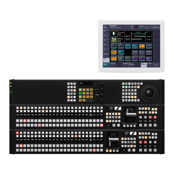
Connection Example Menu display monitor MVS-3000 Multi Format Switcher AC power supply AC power supplies ICP-3000 Control Panel AC power supplies DVI-D DEVICE LAN cable (straight type) DVI cable USB cable System Configuration Examples... -
Page 21: Chapter 2 Names And Functions Of Parts
Names and Functions of Chapter Parts Names and Functions of Parts of the Control Panel The MVS-3000 system is composed by the MVS-3000 For details about monitors that can be connected, consult switcher processor and the ICP-3000 control panel. your Sony representative. -
Page 22: Cross-Point Control Block
Cross-Point Control Block In the cross-point control block, you can select the signals to be used in the M/E bank or PGM/PST bank. b 1st row c Source name displays a Cross-point buttons a Cross-point buttons a) You can select the source signal of the key bus by selecting the cross-point while holding down the button to which any of KEY1 to KEY4 or DSK1 These select the signals used for video processing on this to DSK4 is assigned in the 1st row. - Page 23 When you turn on the button to which [UTIL/SBOX] is Name Description assigned, the buttons in the cross-point control block will SHIFT Performs one of the following be used for utility/shotbox operations. functions, according to the setting made in the Setup menu. 1 “Executing a Shotbox Function with For details, •...
-
Page 24: Transition Control Block
Transition Control Block In the transition control block, you can modify the output of the M/E bank or PGM/PST bank, and perform transitions. Both common transition and independent key transition operations are possible. 6 PRIOR SET button 1 Next transition selection buttons 9 Key delegation buttons 7 Key priority display qs K-SS STORE button... - Page 25 For details about assignments for the transition type Name Description selection buttons, 1 “Setting Transition Control Block REV (reverse) The wipe proceeds in the opposite Button Assignments” (p. 221). direction of [NORM]. NORM/REV The wipe direction alternates between c Transition execution section (normal/reverse) normal and reverse every time a This section is used to carry out a transition and check the...
-
Page 26: Device Control Block
Pressing one of these buttons twice in rapid succession Name Description changes its state so that you can make cross-point KEY1 ON to • Press the corresponding one of these selections on the corresponding key bus. KEY4 ON (DSK1 buttons to cut key 1 to key 4 in or out The key delegation buttons can also be used for copying ON to DSK4 ON instantaneously. - Page 27 Region Overview of assigned operation Name Description selection • Pressing this button and operating the button (location) trackball or Z-ring moves, shrinks, or • This enables the VTR/disk recorder/frame magnifies a key to which the resizer memory operation mode. function is applied. •...
-
Page 28: Flexi Pad
When the resizer operation mode is enabled d Z-ring The effect of operation depends on the operating mode as By turning the ring, you can zoom the key to which the follows. resizer is applied, and change the aspect ratio and perspective. - Page 29 Name Description Name Description KEY SS (key Press this to carry out key snapshot MORE • Displays buttons in the memory recall snapshot) creation/recall/deletion. section for regions not assigned to a By default, this is not assigned to a mode region selection button, so that they selection button, so you must assign it to can be selected.
-
Page 30: Names And Functions Of Parts Of The Menu
Press each button to display the corresponding top menu in with a Mouse” (p. 38). For information about supported the monitor screen. monitors, contact your Sony representative. Press the [Shutdown] button on the bottom right to shut down the control panel. For details about shutting down the control panel, Top Menu List 1 “Shutting down the control panel”... - Page 31 qs b (previous) button and B (next) button 6 Function button area 5 Status area 2 Menu page number button 7 Parameter group button 1 Menu title button 0 Keyframe status 4 HF buttons 9 Previous page button qa Default recall button 8 Parameter setting buttons 3 VF buttons a Menu title button...
- Page 32 i Previous page button This shows the page number of the previously displayed menu screen. Press it to go back to that page. When the [Parent] indication appears, this displays the parent directory (menu level). e Status area j Keyframe status This shows the status of the settings items controlled by the This shows the keyframe status of the reference region.
-
Page 33: Top Menu Window
Top Menu Window 1 Top menu selection buttons 2 [Shutdown] button 3 [Add Favorite] button 4 [Close] button 5 Page number entry section a Top menu selection buttons These display the selected menu. b [Shutdown] button Shuts down the control panel. For details about shutting down the control panel, 1 “Shutting down the control panel”... -
Page 34: Numeric Keypad Window
Numeric Keypad Window h [Trim] button 1 Item display After entering the difference from the current value, press this button to confirm the numeric input. 2 Max./min. value indication 3 Input display i [Enter] button This confirms the entered value. If correctly set, the numeric keypad window closes. -
Page 35: Keyboard Window
Keyboard Window Notes Except when changing source names, the following characters cannot be used. space, \, /, :, ;, , (comma), . (dot), <, >, *, ?, ", | 1 Item display 3 [Close] button 2 Input display 4 [BS] button qs Line feed button 5 [Caps Lock] button qa [Enter] button... -
Page 36: Color Palette Window
Color Palette Window When parameters are assigned as a combination of luminance, saturation, and hue, pressing a parameter setting button displays a color palette window. 1 Color palette buttons 2 Operation buttons 3 Color display 4 Numeric keypad d Numeric keypad a Color palette buttons Press one of these to display the corresponding color in the Use this to enter numeric values for parameters. -
Page 37: Selecting Menus
Top menu selection buttons on the top menu Parameter Adjustment window Number to select Open the top menu (1st menu level) of the corresponding menu for each button. If the [No] parameter is set to “2” and the [Num] parameter is set to “5,”... -
Page 38: Returning Parameters To Default Values
In the Setup menu, you can specify the scroll direction and Returning Parameters to Default whether parameters increase or decrease in relation to the Values mouse wheel rotation. You can also switch the functions of the right and left mouse buttons during parameter setting Press the [Default Recall] button, turning it on, then press button adjustments. -
Page 39: Power Supply And Connectors
Enter the page number for the menu you want to To change the button color register. Select the button you want to change, press [Color Set], and then select the desired color. To register the currently displayed menu To copy button settings Select the button you want to copy, press [Copy], and In the Home >Favorites >Shortcut menu (0021), select then select the target button and press [Paste]. -
Page 40: Rear Panel
REMOTE 1 to 4 connectors (D-sub 9-pin, RS- routing switcher 422A) f UTIL (FM) (utility (frame memory data)) Connect devices supporting Sony 9-pin VTR, VDCP (Video Disk Communications Protocol), or P-Bus connector (RJ-45 compliant) (Peripheral II Protocol) protocols. Intended for future expansion. - Page 41 Settings” (p. 246). o PRIMARY INPUTS 1 to 32 connectors (BNC-type) These connectors allow you to input up to 32 serial digital video signals. 1) For information about devices that can be connected, contact your Sony representative. Power Supply and Connectors...
-
Page 42: Icp-3000 Control Panel
AC IN A and B connectors, there may be a fault in the power circuits. Disconnect the cords from the AC IN A/B connectors, and contact your Sony service representative. • If you force shutdown without performing shutdown processing, setting data may not be saved. - Page 43 AC power cords. The unit is equipped with two power supplies. When A or B power supply is connected, unit operation can proceed. 1) For information about devices that can be connected, contact your Sony representative. Power Supply and Connectors...
-
Page 44: Chapter 3 Signal Selection And Transitions
Signal Selection and Chapter Transitions Video Processing Flow The switch from the current video stream (appearing on The following illustration shows the flow of operations for the corresponding program monitor) to a new video stream carrying out a transition on a switcher bank. is referred to as a transition. -
Page 45: Signal Selection
Signal Selection You carry out signal selection in the cross-point control The following table illustrates the correspondence block of each bank. between buses and cross-point button rows, and the delegation operations. 2nd row Bank Bus name Cross-point Delegation operation 1st row button row M/E-1 Background... -
Page 46: Inhibiting Cross-Point Button Operations
Cross-point control block button numbers Buses for which operations can be inhibited Shift buttons This setting applies to the cross-point buttons in each switcher bank. If you make the setting for one cross-point button, this inhibits operation of all cross-point buttons with the same number in the following buses. -
Page 47: Signal Name Display
Type Description Independent Signal Name Display page transition You can attach a name (source name) to each signal NAM (non- The current video and – assigned to a cross-point button, with a maximum of 16 additive mix) new video signals are selectable characters. -
Page 48: Procedure For Basic Transition Operation
For the transition to change the key priority, set the Procedure for Basic priority for after the transition. Transition Operation 1 “Key Priority For details about operations, Setting” (p. 49). Select the new video used for the transition. • In the background B row of cross-point buttons, Key priority display select the new background video. -
Page 49: Key Priority Setting
For a gradual transition such as a mix (dissolve) or Setting the Key Priority in the wipe: Press the [AUTO TRANS] button, or Transition Control Block operate the fader lever. To execute a transition by pressing the [AUTO TRANS] button, first set the transition rate Key priority display (specified as the duration of the transition) (1 p. -
Page 50: Setting The Key Priority By A Menu Operation
Notes After transition Before transition The [BKGD] button is only effective when in the mode for changing the key priority for after the CRNT NEXT transition. When the next transition selection button [KEY PRIOR] is on, the selected key appears on top on the preview monitor. -
Page 51: Executing A Transition
When a key is selected for the next transition • In the multi-program mode, you can use a preset color while a key is inserted mix only when selecting the background for the next transition. One-stroke mode and one-time mode •... -
Page 52: Transition Indicator Function
Transition Indicator Function Notes Whereas you can enter a value of up to 999 in frame input In each of the switcher banks, to the left of the fader lever mode, a value not smaller than 10 seconds cannot be is a transition indicator. -
Page 53: Pattern Limits
Displaying the transition rates in a menu In the region selection buttons, select the switcher and changing the settings bank. For each of the banks, you can display the transition rate, Press the [TRNS SEL] button in the memory recall independent key transition rate and fade-to-black section. - Page 54 Adjust the following parameter. Parameter Adjustment Pattern Limit Pattern limit Executing a pattern limit transition Press [PTN LIMIT], turning it on. The button you pressed lights amber. Execute the transition. The transition progresses as far as the set pattern limit. Even if the transition completes, the cross-point button assignments of the background A and B buses do not LIMIT SET button...
-
Page 55: Executing An Auto Transition
execution continues for the time specified by the dedicated transition rate in the menu setting, as far as the state of the next transition. 1 “Selecting the Bank to For details about settings, Make the Settings” (p. 251). To set the transition rate when the pattern limit is released In the <Pattern Limit Release>... -
Page 56: Combining Auto And Manual Transitions
To resume a paused transition: Resume moving the fader lever. [Non Sync] indicator Combining Auto and Manual Transitions Using the [AUTO TRANS] button, the [CUT] button, and the fader lever, use the following procedures. [Sync] indicator Moving the fader lever during an auto transition During an auto transition started by pressing the [AUTO TRANS] button, operating the fader lever immediately... -
Page 57: Transition Preview
In the bus fixed mode there is a fixed relationship between On the preview monitor, you can check the effect of the position of the fader lever and the signal output on the transition. background A bus and B bus. Depending on the direction To terminate a transition preview of the transition, the fader lever must therefore always be moved in a particular direction, as shown in the following... - Page 58 When carrying out such a combination of transitions on the same key as auto transitions (1 p. 55), the result varies Example: When the independent key transition [AUTO TRANS] button is pressed later depending on the timing at which the two respective [AUTO TRANS] buttons are pressed.
-
Page 59: Basic Independent Key Transition Operations
Select one or more of the delegation buttons [KEY1] Example 2: When the common transition [AUTO TRANS] to [KEY4] ([DSK1] to [DSK4] in the PGM/PST button is pressed later bank), turning them on. You can press more than one button at the same time. Select the transition type. -
Page 60: Setting The Independent Key Transition Rate
To copy keys between blocks Press the [ENTR] button. Press the [DSK3] button in the PGM/PST bank while holding down the [KEY1] button in the M/E-1 bank. Setting the independent key transition rate Information for key 1 of M/E-1 is copied to key 3 of PGM/ by a menu operation PST. - Page 61 Parameter Adjustment Transition Rate Transition rate Displaying the transition rates in a menu and changing the settings For each of the banks, you can display the transition rate, independent key transition rate and fade-to-black transition rate, and change the settings (1 p.
-
Page 62: Chapter 4 Keys
Keys Chapter Type Description Clean Overview mode Color vector The key signal is created from a Can be combination of the luminance and used chrominance components of the A key is an effect in which a part of the background image key source signal. -
Page 63: Key Modifiers
Type Description Image Key Modifiers Emboss This applies an – embossing effect to Edge modifiers the outline of the key. You can adjust the You can apply borders and other modifiers to the edge of width and position of the embossing and the the key image (1 p. -
Page 64: Key Memory
When the box generator is selected, a mask using a Notes rectangular signal is formed. This function uses the resizer, and therefore the normal When the pattern generator is selected, you can select effect of the setting is not obtained while using DME wipe the pattern and apply modifiers. -
Page 65: Key Setting Menus
This section describes basic procedures for making key Parameter Adjustment settings using the menus, taking the M/E-1 >Key1 menu as Density Key density an example. Filter Filter coefficient Operations in the Key menus are the same for each switcher bank. a) Setting this value to 1, produces the “through”... -
Page 66: Selecting The Key Fill And Key Source
If you selected [Split] in step 5, select the key source Selecting the Key Fill and Key using any of the following methods. Source • In the cross-point control block, press the button in the 2nd row while holding down the [KEY1] button Selecting the key fill and key source in the 1st row. -
Page 67: Chroma Key Composition And Basic Settings
If [Split] is selected, select the key source signal. Chroma Key Composition and Basic Settings In the <Assign> group, select the video signal or key signal from the V/K pair to assign to the key source. A key signal based on a particular color is used to cut out Press [Set Xpt]. -
Page 68: Key Adjustments (Menus)
Key active Carry out auto chroma key adjustments. Also carry out manual adjustments (see next item), if When this function is off, only the foreground is output necessary, to obtain an optimum chroma key image. and you can make adjustments for color cancel (see the next paragraph). - Page 69 color cancel effect applied. This can therefore be used to Adjust the following parameters. provide an impression of smoke, for example. When the Y balance function is applied to the color cancel Parameter Adjustment key, the relevant part is output in its original color without Clip Chroma key reference level canceling, and therefore it is possible to combine colors...
-
Page 70: Key Edge Modifications
When setting [Key Position] on and adjusting the Parameter Adjustment color cancel key edge position Clip Luminance range Parameter Adjustment Gain Key gain H Phase Move left and right edges of the Luminance Luminance color cancel key simultaneously Left Move left edge of the color cancel Adjusting the video signal Right Move right edge of the color... - Page 71 • When separate edge is off You can select whether to use a single color matte or a two-color combination color matte in the <Edge Parameter Adjustment Matte> group. Width Width 1 “Carrying out a color For the color mix operation, Density Density mix for the key edge fill matte”...
- Page 72 Off: Key drop off mode Parameter Adjustment Size Pattern size Notes Soft Edge softness of the pattern In key drop off mode, an edge can only be set below the Pattern Pattern number key if drop border or shadow is selected for the edge type. a) The pattern is the same as the wipe.
-
Page 73: Mask
When turning [Angle] on in the <Rotation> group You can change this pattern by pressing [Pattern and inclining the pattern Select] to open the menu for edge color mix dedicated wipe pattern selection (Mix Pattern Parameter Adjustment Select menu), and make adjustments by pressing Angle Rotation angle of pattern [Pattern Adjust] to open the menu for pattern... -
Page 74: Key Modify Clear
Using the blink function When Pattern is selected For example, to perform settings for key 1 on the M/E-1 Parameter Adjustment bank, use the following procedure. Size Pattern size Soft Edge softness of the pattern Open the M/E-1 >Key1 >Transition menu (1116). Pattern Pattern number In the <Blink>... -
Page 75: Selecting The Key Type
In the Flexi Pad mode selection buttons, press [KEY [PAGE 3/3] ADJ]. Press the [M/E1] region selection button. In the memory recall section, press the [KEY1] button. The button displays in the memory recall section now appear as shown in the following illustration. Pressing the [PAGE 1/3] >... -
Page 76: Resizer
Applying modifiers to the key edge 1 “Making auto For details about these parameters, chroma key adjustments” (p. 69). [BDR] button: Applies a border to the edge. [DROP BDR] button: Applies a drop border to the edge. Setting the show key function [SHDW] button: Applies a shadow to the edge. -
Page 77: Two-Dimensional Transformations And Rotation Of Keys
Two-Dimensional Transformations For example, the upper and Rotation of Keys limit of the movement Center of image range is here. Notes When the screen aspect ratio is 4:3 in HD format, when the resizer is used to shrink a video image, this is applied to the 16:9 screen including the added video on the left and right sides. -
Page 78: Resizer Interpolation Settings
Hold the ASP, LOC, or ROT button down while Resizer Interpolation Settings carrying out the operation of step 5 to enable fine adjustment (fine mode). For example, to make the interpolation settings for key 1 of the M/E-1 bank, use the following procedure. Use the trackball for the operation. -
Page 79: Resizer Crop/Border Settings
Parameter Adjustment Parameter Entered value Setting Mode Degree of motion detection Left = –1.50 Right = 1.50 In the <Filter Mode> group, select the method used to –1.5 Left = –1.50 show the picture reduced or expanded. Right = 1.50 Mode1 (standard): Even when the picture is reduced, add compensation so that it can be seen clearly. -
Page 80: Applying Resizer Effects
Parameter Adjustment Parameter Adjustment Bound Soft Border boundary softness To soften the inner edge of a border Applying Resizer Effects In the Border/Crop menu, press [Border Soft]. For example, to make the effect settings for key 1 of the Set the following parameter. M/E-1 bank, use the following procedure. -
Page 81: Key Snapshots
Set the following parameters. Off: Nothing is saved in the register. Lit: Settings are saved in the register. For a register holding a snapshot, the register name is Parameter Adjustment shown as up to eight characters. Horizontal defocusing Vertical defocusing Notes Horizontal and vertical If you save a key snapshot to a button to which settings... - Page 82 In the memory recall section, hold down the [STOR] button, and press the button (any of [1] to [4]) for the register in which you want to save the key snapshot. To recall a key snapshot For example, to recall a key snapshot for M/E-1 key 1 saved in register 1, select the M/E1 region and KEY1, then proceed as follows.
-
Page 83: Chapter 5 Wipes
Wipes Chapter Note that the available modifiers may depend on the Overview pattern you are using (1 p. 87). Specifying the wipe direction (Direction) A wipe is a transition from the current video stream to a Specify the direction of the wipe effect. new video stream, using a wipe pattern. - Page 84 When you selected Border or Soft Border, select the Border edge fill signal in the <Edge Fill> group. Applies a border to the pattern. Utility 1 Bus: Signal selected on the utility bus Matte: Signal from the dedicated color matte generator Depending on the selection in step 4, carry out the following operation.
- Page 85 When Pattern is selected To adjust colors 1 and 2, turn on [Color1] or [Color2] respectively, then adjust the following parameters. Parameter Adjustment Size Pattern size Parameter Adjustment Soft Edge softness Luminance Luminance Pattern Pattern number Saturation Saturation “Wipe Pattern List” (1 p. 264).
-
Page 86: Aspect Ratio
In the <Rotation> group, select the rotation type. Table 1: Buttons and assigned settings Depending on the selection in step 2, set the following Button Setting name parameters. WIPE Wipe position for common transition When Angle is selected Table 2: Buttons assigned to functions Parameter Adjustment Button... -
Page 87: Wipe Modify Clear
Parameter Adjustment H Multi Number of repetitions of pattern horizontally V Multi Number of repetitions of pattern vertically Invert Type Replication layout Aspect Off Aspect On Possible combinations of wipe patterns Open the M/E-1 >Wipe >Main Modify menu (1155). and modifiers Press [Aspect], turning it on. -
Page 88: Basic Procedure For Independent Key Transition Wipe Settings
Setting the wipe position (Positioner) Basic Procedure for Independent There are two methods of setting the wipe position: using Key Transition Wipe Settings the device control block, or in a menu. To set the wipe position using the trackball Selecting the independent key transition wipe pattern Press the [M/E1] button in the device control block, You select the independent key wipe pattern from the list... -
Page 89: Wipe Snapshots
Replicating the wipe pattern Parameter Adjustment (Multiplication) Position H Horizontal position Position V Vertical position In the Key1 Wipe Adjust menu, press [Multi], turning it on. 1 p. To move the pattern from its current position to Set the following parameters. the center through the course of a transition Press [Auto Center], turning it on. -
Page 90: Wipe Pattern Operations In The Flexi Pad
Button displays This switches the memory recall section to wipe In the Setup menu, you can select whether the memory snapshot mode. recall buttons show the pattern number or register name. Adjustment knobs 1 “Settings for the Flexi Pad and Wipe For details, Snapshot Menus”... -
Page 91: Editing The Wipe Pattern
When soft edge is selected Editing the Wipe Pattern Parameter Adjustment By pressing the [EDIT ENBL] button to switch the Edge softness memory recall section to editing mode, you can edit the selected wipe pattern. When edge matte is selected To exit from the editing mode, press the [EDIT ENBL] Parameter Adjustment... -
Page 92: Saving, Canceling, And Deleting Edited Wipe Patterns
Wipe modify clear When the [WIPE] button is held down, holding down the region selection button for the selected region together returns all the wipe settings of the region to the initial status settings. 1 “Saving User-Defined For details about initial status, Settings”... -
Page 93: Chapter 6 Dme Wipes
DME Wipes Chapter Notes Overview • Resizer DME wipes can only be set for keys that support resizer/key edge. • Resizer DME wipes cannot be used on keys where A DME wipe is a wipe transition that uses an image resizer is enabled. -
Page 94: Dme Wipe Pattern Variations And Modifiers
Pattern group Effect Pattern numbers Used in backgrounds Used in keys Mosaic In the first half of the transition, a mosaic is gradually 1701 — applied to the old video, then at the 50% point the inner image changes to the new video. In the second half, the mosaic effect on the new video is gradually reduced, returning to the original image at 100%. -
Page 95: Basic Procedure For Dme Wipe Settings
Specifying the DME wipe direction • A DME wipe pattern cannot be used as the source for a (Direction) pattern key or mask. You can specify the DME wipe direction (normal/reverse). Basic Procedure for DME To specify the DME wipe direction in a menu Wipe Settings Open the M/E-1 >DME Wipe >Edge/Direction menu (1164). - Page 96 Setting the DME wipe position (Positioner) In the <Crop Mode> group, press [Crop], turning it on. Set the following parameters. Open the M/E-1 >DME Wipe >Modify menu (1165). Parameter group [1/2] Press [Position] in the <Position> group, turning it on. Parameter Adjustment Set the following parameters.
-
Page 97: Dme Wipe Modify Clear
“Dead Zone” Transitions Transitions Cropping Cropping t: Transition execution t: Transition execution time time y: Change in transition and y: Change in transition cropping amount and cropping amount To set the timing of transition completion DME Wipe Modify Clear When the execution mode for a DME wipe crop transition is set to [Last 5%], you can select the timing of transition completion from 70% ([Last 30%]), 95% ([Last 5%]), and Press [Default Recall] at the lower left of the menu screen,... -
Page 98: Basic Procedure For Independent Key Transition Dme Wipe Settings
For details about image patterns and numbers, - Parameter Adjustment 1 “Resizer DME Wipe Pattern List” (p. 265). Vertical position To return the pattern position to the center of the Basic Procedure for Independent screen Key Transition DME Wipe Settings In the <Position>... -
Page 99: Dme Wipe Snapshots
To set the operation for DME wipe crop transition Saving to and recalling these registers can be performed execution using the Flexi Pad or a menu operation. 1 “DME Wipe For details about Flexi Pad operations, In the <Crop Mode> group of the Key1 DME Wipe Pattern Operations in the Flexi Pad”... -
Page 100: Editing The Dme Wipe Pattern
Note, however, that the pattern numbers for DME wipe Parameter group [2/2] patterns have four digits 264). Parameter Adjustment Luminance Editing the DME Wipe Pattern Saturation By pressing the [EDIT ENBL] button to switch the memory recall section to editing mode, you can edit the Buttons for positioning the DME wipe selected DME wipe pattern. -
Page 101: Saving, Canceling, And Deleting Dme Wipe Snapshots
When the [SIZE] button is lit green, you can specify the effect size with the adjustment knobs. Parameter Adjustment Effect size a) The effect size when SIZE is off is taken as 100. DME wipe modify clear With the [DME WIPE] button held down, pressing and holding down the region selection button for the selected region returns the DME wipe settings to their initial status. -
Page 102: Overview
Frame Memory Chapter Types of image and terminology used Overview The following types of image are handled in frame memory. Freeze image: An input image that has been frozen, but not saved to memory. Frame memory is a function whereby a frame of input Still image: A freeze frame that has been saved to memory video can be frozen and written to memory, for further use as a file. -
Page 103: Still Image Operations
Pair mode • The following names cannot be used for folders. Flash1, Flash2 By enabling the pair mode, you can link FM1 and FM2, CON, PRN, AUX, CLOCK$, NUL, COM0, COM1, FM3 and FM4, FM5 and FM6, and FM7 and FM8. For COM2, COM3, COM4, COM5, COM6, COM7, COM8, example, when a freeze or image processing is carried out COM9... - Page 104 1 Auto store status display 2 Display of available image capacity 3Target FM selection buttons 4 Pair selection buttons 7 Frame memory folder selection area Frame memory 5 [Pair] button selection area 9 [Find] button 6 File selection area 8 [Direct Recall] button a Auto store status display c Target FM selection buttons...
-
Page 105: Selecting An Input Image
Status display f File selection area File name (e.g., image001) and thumbnail: File output in You can select from the displayed still image files or clip progress files. Black: Black signal output in progress Through: Input image output in progress File information detail display Freeze: Freeze in progress Record: Continuous image capture (i.e., recording) in... -
Page 106: Selecting Outputs And Target Frame Memory
Selecting the signal on a frame memory When [Pair] is On: Regardless of whether you press source bus FM1 or FM2, the pair is selected. When [Pair] is Off: One of the targets must be This section describes an example of selecting the signal selected. -
Page 107: Recalling Still Images (Recall)
An orange bar appears on the selection button for the Notes destination folder. The following names cannot be used: CON, PRN, AUX, CLOCK$, NUL, COM0, COM1, Press [Freeze Enable], turning it on. COM2, COM3, COM4, COM5, COM6, COM7, The signals of frame memory source buses 1 and 2 are COM8, COM9 assigned to the pair of FMs selected in step 2, and a LPT0, LPT1, LPT2, LPT3, LPT4, LPT5, LPT6, LPT7,... -
Page 108: Image Output
Recalling a still image To search by file name To recall a still image file saved in memory using the Press [Find]. thumbnails, and assign it to an FM output, use the following procedure. The Find window appears. Open the Frame Memory >Still >Recall menu (2511). When [Pair] is on, only pair files (each consisting of a main file and a sub file) are displayed. -
Page 109: Continuously Capturing Still Images (Record)
In this menu, you can also enable the frame memory operation (up to four characters). This string can be V/K mode (1 p. 106). specified using a menu before carrying out the capture. The first string is automatically used as the clip name In the frame memory selection area, select the FM when the images are treated as a frame memory clip. -
Page 110: Recalling A Continuous Sequence Of Still Images (Animation)
Press [Stop] to stop recording. When [Pair] is off, both single files and pair files appear. Even if the recording time is set, you can still stop recording before the set time has elapsed. In the frame memory selection area, select the frame memory to be assigned (1 p. -
Page 111: Frame Memory Clip Function
• The frame memory saving mode is set to “save with Notes ancillary data.” • The effect is built with the selected files, in increasing • Ancillary data is present in the saved or recalled frame order of the last three characters of the file name. If you memory file. -
Page 112: Recalling Clips
To recall in direct recall mode Recalling Clips Direct recall means that pressing a thumbnail immediately recalls the file. In this mode, only the front thumbnail file is recalled. Recalling a clip You can recall a clip from each of frame memories 1 to 8. In step 6 of “Recalling a clip”... - Page 113 To delete the parts of a clip file other than the playback part (trimming) Set the playback start point and stop point. Press [Trim]. Check the message, then press [Yes]. Using the device control block to play back clips Notes A frame memory clip must first be recalled with a menu Current position Status buttons...
-
Page 114: Clip Creation
Creating a new folder Clip Creation Open the Frame Memory >Folder menu (2551). You save a movie as a clip. Select [New]. Notes Enter a folder name and press [Enter]. If the number of frame memory clips exceeds 100 single files (50 pair files), an error appears. -
Page 115: Recording And Playback Of Ancillary Data
1 “Saving a Frame Memory Clip with the playback start point and end point. For details about Ancillary Data” (p. 216). devices that are used for playback, contact your Sony service or sales representative. Recording ancillary data Open the Frame Memory >Clip >Ancillary Enable To record in a frame memory clip, use the Frame Memory menu (2525). - Page 116 Setting a clip transition Use either of the following methods to set the background transition start point independently of the This section describes a clip transition using FM1&2 Clip clip playback timing. on the M/E-1 bank as an example. • Move the fader lever to the desired position, and in Notes the <BKGD Transition Set Timing>...
-
Page 117: Image Data Management
This section describes FM1 and FM2 as an example. Image Data Management In the Frame Memory >Still >Recall menu (2511) or Frame Memory >Clip >Recall menu (2521), recall the pair file. You can carry out the following operations on the files that were created when images were saved. -
Page 118: Renaming Files
Open the Frame Memory >File >Rename menu For details about HDDs that can be connected, contact (2546). your Sony service or sales representative. In the status area, regardless of whether pair mode is on or off, all of the saved files appear as thumbnails. -
Page 119: Recalling Files
In the <Backup> group, perform one of the following. Notes • To replace the existing data, press [Replace]. When you execute [Replace], any existing data in • To save in addition to the existing data, press frame memory is lost immediately before the recalling [Append]. -
Page 120: Extracting Images From A Video Tape
This starts the backup, and when completed a message Stop the playback on the external device, and press the appears. [OK] button. Stop the recording on the external device, and press the Extracting Images from a Video Tape [OK] button. To save the file list in memory, press [File >File Name By recording a clip or still image stored on a video tape as Data]. - Page 121 Notes For extraction as a pair file, the main file and sub file must have the same number of frames. In the Frame Memory >Clip >Record menu (2523), record the tape image as a clip (1 p. 114). Open the Frame Memory >File >Auto Extraction menu (2542).
-
Page 122: Chapter 8 Color Backgrounds, Copy And Swap, And Other Settings
Color Backgrounds, Copy Chapter and Swap, and Other Settings Parameter Adjustment Color Background Setting a color mix The dedicated generators generate color signals, and these To combine color 1 and color 2, use the following can be used as color backgrounds in video effects. procedure. -
Page 123: Copy And Swap
When turning [Multi] on and using replications of To interchange color 1 and color 2, press the [Color the same pattern Invert] button, turning it on. Parameter Adjustment H Multi Number of repetitions of pattern Copy and Swap horizontally V Multi Number of repetitions of pattern vertically Invert Type... -
Page 124: Copy And Swap Operations
Wipe copy and wipe swap Color data copy and swap You can copy and swap the wipe settings among the banks You can copy or swap the color data among the following as follows. color generators. Target bank Target data Target bank Target keyer and data M/E -1... -
Page 125: Misc Menu Operations
The status area shows lists for the copy/swap source on Port Settings for Control from an the left, and the copy/swap destination on the right. External Device In the <Data Select> group, select either of the following. Enabling or disabling control from an external device Wipe: Applies operations to wipes in the transition control block. -
Page 126: Displaying A List Of Transition Rates And Changing The Settings
In the status area if the Misc >Transition >Key/ME/ Displaying a List of Transition Rates FTB menu (3231), press [M/E-1]. and Changing the Settings In the <Transition Rate> group, press [Key K1-K4]. In the Misc >Transition >Key/ME/FTB menu (3231), for To insert (on) or remove (off) keys individually, press each bank you can display a list of the M/E (or PGM/PST) [Key(On) K1-K4] or [Key(Off) K1-K4]. -
Page 127: Router Control Menu Operations
Selecting the level To set an RGB clip: Turn on [RGB Clip] in the <RGB Clip> group, and select the item to set in the <RGB In the <Level Button No> group at the lower right in the Clip Adjust> group. above illustration, press the level for switching. -
Page 128: Chapter 9 Special Functions
Special Functions Chapter Open the Misc >Enable >Side Flags menu (3213). Side Flags The status area shows the buttons for Bkgd A and Bkgd B for each of the banks. Overview In the <M/E-1 Side Flags> group, press [Bkgd B]. To display a menu for the aspect ratio 4:3, auto The term “side flags”... -
Page 129: Wipe Action On Images With Side Flags
Creating an image with side flags Wipe from a 4:3 image to another 4:3 image (when side flags are on for both For example, to create an image with side flags in the images) background B row of the M/E-1 bank, use the following procedure. - Page 130 DME wipe from a 4:3 image to a 16:9 image DME wipe from a 4:3 image to another 4:3 image (when side flags are on for both Wipe action using slide (No. 1001) images) Wipe action using squeeze (No. 1031) 16:9 image 4:3 image (side flags on)
-
Page 131: Chapter 10 External Devices
For details about the devices that can be connected, keyframe effect, since the actions are not executed in the consult your Sony representative. reverse direction. • The following keyframe functions cannot be used. -
Page 132: Control Of P-Bus Devices
Two lists appear in the status area. The left list displays Control of P-Bus Devices the combinations of devices and actions. The settings in this list will be saved as keyframe point data. The right list is for selecting the action. You can control P-Bus (Peripheral II protocol) devices Select the ID (0 to 23) of the device you want to set. -
Page 133: P-Bus Trigger
executed. In this case, the Rewind Action setting is still Press the [ENTR] button. valid. 1 “Setting the First Keyframe When a For details, Control of GPI Devices Rewind is Executed” (p. 236). Carrying out a Direct Store You can control GPI devices from this system, through the You can carry out a Learn with the register number GPI output port of the switcher. -
Page 134: Control Of Vtrs, Extended Vtrs, And Disk Recorders
Two lists appear in the status area. not executed; when the [RUN] button is pressed, then the The “GPI Output” list on the left shows the relation first keyframe action is executed. between ports 1 to 8 for the GPI timeline and the To execute an action when the [REWIND] button is trigger pulse output destination ports. -
Page 135: Controlling The Tape/Disk Transport
Button Operation Controlling the Tape/Disk Transport VAR (variable speed Press this button and turn the Z-ring play) to play or rewind the tape, disk or To switch to VTR/disk recorder/frame memory frame memory clip at a variable operation mode speed (–1 to +3 times normal playback speed) and direction To control a VTR/Extended VTR/disk recorder with the proportional to the rotation angle of... -
Page 136: Checking Vtr/Disk Recorder/Extended Vtr Information
Jog mode Recording to VTRs and disk recorders Pressing the [JOG] button, lighting it amber, changes the You can record to the VTR or disk recorder selected in the Z-ring to jog mode. In this mode, you can advance material device control block. -
Page 137: Cueup & Play
Status: Status of each device. Cueup & Play Operating When VTR is used When video disk status communications You can use the device control block or Device menu to display or Extended save Cueup & Play settings (start point timecode, stop VTRis used point timecode, start delay time, and so on) for a VTR, disk XXXX... - Page 138 The entered register number or corresponding register Pad. Alternatively, make the setting in the Cueup & number appears in the alphanumeric display. If the Play menu. number is followed by a letter “e” or “E,” this indicates If no setting is required, continue to step 10. the following.
-
Page 139: Vtr/Disk Recorder/Extended Vtr Timeline
The status area shows the device number, register Select the device. number, status information, current time, start point, stop point, and start delay time. In the <Mode> group, press [Loop] or [Recue], turning it on. Select the device. VTR/Disk Recorder/Extended VTR Carry out any of the following operations as required. - Page 140 In this example, when keyframe 1 is executed, the first 15 - Operation with no problems: frames consist of clip playback and the remaining 15 KF1 action Operating KF2 action frames show the 15th frame as a still image. setting status of file A setting When executing the timeline using a disk recorder, also...
- Page 141 The lower list is used for setting the action for the If setting a stop point, in the <Stop TC> group, press device selected above. The list shows the port name, the [Set] button. current file, current time, status information, start If not setting a stop point, skip to step 11.
-
Page 142: Disk Recorder/Extended Vtr File Operations
button is pressed, then the first keyframe action is Notes executed. • File update information is not shown when using the To execute an action when the [REWIND] button is video disk communications protocol. pressed, it is necessary to set this action (Rewind Action). •... - Page 143 Open the Device >DDR/VTR >File List menu (5333). Press [New File]. Enter a file name and press [Enter]. You can enter up to eight characters (Fixed 8 Character mode) or 23 characters (Variable Length mode). For details about the file name character count mode in the video disk communications protocol, 1 “Making Detailed Settings on the External Device Connected to the Serial Port”...
-
Page 144: Chapter 11 Keyframes
Keyframes Chapter • To reproduce a frame memory still image or a clip of Regions them by recalling a snapshot or keyframe, you must have the same images that were present in the frame memory when you saved the snapshot or keyframe. Therefore, when saving a snapshot or keyframe using frame The term “region”... -
Page 145: Overview Of Keyframes
Work register Effect Attributes This is a temporary register used when editing keyframes. When you recall an effect, it is read from the effect register An individual effect may also have attached special into the work register, and when you save, the contents of conditions relating to switcher operation when the effect is the work register are written to the effect register. -
Page 146: Time Settings
Undo an edit operation: Undoes the effect of the last Keyframe duration operation to insert, modify, delete, or paste a keyframe. Keyframe number Duration modes In keyframe editing, there are two duration modes; switch Effect duration between them in the Flexi Pad (1 p. -
Page 147: Paths
Changes in the effect duration caused by 1 “Path For details about the path setting procedure, deleting a keyframe Setting” (p. 159). • When the effect is stopped on a keyframe, a delete Switcher path settings operation deletes the keyframe, and reduces the effect duration by the duration of the deleted keyframe. -
Page 148: Effect Execution
Run mode setting Item Paths that can be set You can select from the following run modes for when the Color Bkgd Overall path settings for color effect is executed. backgrounds are made Color Bkgd DIRECTION: Specifies the effect execution direction. simultaneously. -
Page 149: Displaying The Timeline Menu
Displaying the Timeline Menu By displaying the Key Frame >Time Line menu (6111), you can view keyframe effects on the timeline for each region, and the associated information. Interpreting the Timeline Menu The menu screen consists of the following principal parts. 1 Keyframe status 2 Region name and register number... -
Page 150: Settings In The Timeline Menu
Setting the display of regions in the Settings in the Timeline Menu Timeline menu on or off When [Active Region] is off, to select which regions are Selecting the region to be displayed displayed in the Timeline menu, use the following procedure. - Page 151 Pressing the [MORE] button or the [EXIT] button in the Pressing one of the amber or yellow lit buttons, while memory recall section restores the memory recall section holding down the [EFF] button, turns the button green to the previous screen. to indicate its corresponding region as the new reference region.
-
Page 152: Specifying The Region And Edit Points
This switches the memory recall section to the master Specifying the Region timeline recall mode. and Edit Points Selecting the Region in which Editing Applies Selecting by control panel Select the region in which the editing is applied by the effect consisting of keyframes, using the region selection Press the [BANK SEL] button. -
Page 153: Specifying An Edit Point
Selection screen for regions assigned to buttons in • To move the edit point to a specified timecode, press the the memory recall section [GOTO TC] button, then enter the timecode value, and press the [ENTR] button to confirm. To enter a difference value When moving to a point specified with the [GOTO KF] button or [GOTO TC] button, you can also enter the difference from the current keyframe number or timecode... -
Page 154: Creation
Page 1 button display This inserts the current image as the second keyframe after the first keyframe. Repeat steps 4 and 5 to create the required number of keyframes. To insert a new keyframe before an existing keyframe Hold down the [SHFT] button and press the [INS] button, to insert a new keyframe before the current keyframe. - Page 155 Using image transformations or adding special effects, Press the [MOD] button. Alternatively, hold down the modify the keyframe. [SHFT] button and press the [MOD] button. 1 “Differences in the For the difference in the result, Press the [MOD] button. changes when a number of keyframes are modified” 155).
-
Page 156: Deletion
Deletion : Background A : Background B Deleting keyframes Press the [EFF] button, then press the [EDIT ENBL] Keyframe 1 Keyframe 2 Keyframe 3 Effect execution button, turning it on. Stop the effect at the desired edit point. Modify keyframe 2. (Changing the position of When the edit point is on a keyframe, this is what you background B in the horizontal... -
Page 157: Copying
Move the edit point to the position to which you want Pause to move the keyframe. To apply a pause to a keyframe, use the following Press the [PSTE] button. procedure. This inserts the keyframe you have moved after the Press the [EFF] button, then press the [EDIT ENBL] current keyframe. -
Page 158: Undoing An Edit Operation
The display changes as follows, prompting you to enter the loop count. Before deletion COUNT Deletion Enter the loop count. (Here, by way of example, “15” After deletion is entered.) : Loop range To specify a loop count, enter a number in the range 1 to 99. -
Page 159: Time Settings
Use the numeric keypad to enter the desired timecode Time Settings value as a maximum of six digits. For example, to set 3 minutes 7 seconds and 15 frames, enter 30715. You can determine the execution time of an effect by You can also use the [TRIM] button to enter a setting either the keyframe duration or the effect duration difference value... - Page 160 A path cannot be set, even if a category is selected, using S-Curve: The rate of change accelerates and the [M/E-2] button on the 1st row or buttons on the 4th decelerates before and after a keyframe, so row. that the rate of change is maximum midway between two keyframes.
-
Page 161: Executing Effects
Xpt Hold off: When replaying a keyframe, Enter the number of the register in which the effect you change the inputs to the settings saved in want to execute is saved, and press the [ENTR] button. memory. This recalls the effect saved in the register. Xpt Hold on: When replaying a keyframe, do not change the inputs. -
Page 162: Saving Effects
When the [NORM/REV] button is lit: Each time the Press the [STOR] button. effect is executed, the direction reverses. Enter the register number to save with the numeric keypad buttons. Executing an effect up to the next keyframe To search for an empty register, instead of entering a number, press the [.] (period) button. -
Page 163: Creating And Saving A Master Timeline With The Menu
Press the region selection button [MSTR], turning it Press the buttons for the regions you want to save on the master timeline (here, [M/E-1] and [P/P]), turning them on. The display shows the number of the register last used for master timeline register operation. Press the region selection button [MSTR], turning it Press the [EDIT ENBL] button, turning it on. -
Page 164: Register Operations In The Menus
Select a region. Press the region display in the upper part of the list, and in the selection window select the region. You can select more than one region. To select all regions, press [ALL]. To select all You can select more than one region. switcher-related regions (M/E, P/P, User), press [SWR To select all regions, press [ALL]. - Page 165 • Name: Attach a name to a register. To select all registers, press [ALL]. To copy without transferring the name, in the Copy Write-protecting the contents of the effect group, press [W/o Name], turning it on. register In the <Copy> group, press [Copy]. Notes This carries out the copy.
-
Page 166: Displaying A List Of Effect Registers For Editing
Attaching a name to an effect register Register containing data: Orange inner border. If, however, there are one or more locked regions, the display is in red. Open the Effect >Effect 1-99 >Rename menu (6227). Write-protecting the contents of the Press the region display in the upper part of the list, and in the selection window select the region. -
Page 167: Chapter 12 Snapshots
Snapshots Chapter The rest of this section describes the snapshots that apply Overview to a particular region or regions. Snapshot Attributes The term “snapshot” refers to a function whereby the various settings required to apply a particular effect to an An individual snapshot may also have attached special image are saved in memory as a set of data, for recall as conditions relating to switcher operation when the... -
Page 168: Snapshot Operations In The Flexi Pad
1 “Interfacing with External Devices” For details, Snapshot Operations in 254). the Flexi Pad Clip Event: Recall a frame memory clip immediately after the snapshot is recalled. Auto Play: Play a frame memory clip immediately after the snapshot is recalled. SNAPSHOT button Table of available attributes Alphanumeric display... -
Page 169: Saving And Recalling Snapshots
button green to indicate its corresponding region as the new reference region. For details about the precedence order for becoming 1 “Reference region” (p. the reference region, 144). The alphanumeric display shows the name of the reference region and the number of the register last recalled for that region. -
Page 170: Recalling A Snapshot
• When the reference region is M/E-1 or P/P For details about the method of region selection, 1 “Selecting regions in the Flexi Pad” (p. 150). Notes The regions that can be selected simultaneously are those assigned to the region selection buttons and the memory recall section buttons (1 p. -
Page 171: Snapshot Operations In The Menus
a) When Xpt Hold mode is selected in the Setup menu. The alphanumeric display shows the number of the b) When Key Disable mode is selected in the Setup menu. last recalled register on the bank. For details about the operation mode of the [XPT HOLD] button, 1 “Setting the operation mode of the Press the [BANK SEL] button, and select the bank for... - Page 172 To apply the effect dissolve attribute You can select more than one region. To select all regions, press [ALL]. Press [Effect Dissolve], turning it on. Press [OK]. Set the dissolve duration. Select a register. Parameter Adjustment To select all levels, press [ALL]. Eff Diss Dissolve duration Duration...
-
Page 173: Snapshot Status Display
To play the clip as soon as it is recalled, press [Auto Setting Key Snapshot Attributes Play], turning it on. Applying key snapshot attributes Snapshot Status Display Open the Snapshot >Key Snapshot >Attribute menu The Snapshot >Snapshot >Attribute menu (6321) displays (6351). -
Page 174: Editing Snapshot Registers
Editing Snapshot Registers You can carry out the following editing on snapshot registers. (You can use similar procedures also on master snapshot, wipe snapshot, DME wipe snapshot and key snapshot registers.) • Lock: Write-protect the contents of the register. • Copy: Copy the contents of one register to another register. - Page 175 Deleting a snapshot Open the M/E-1 >Misc >Snapshot menu (1177) and press [Delete]. As required, press [Bank Sel] to change the bank. Press the button for the number or name you want to delete. Renaming a snapshot register Open the M/E-1 >Misc >Snapshot menu (1177) and press [Rename].
-
Page 176: Chapter 13 Utility/Shotbox
Utility/Shotbox Chapter To execute the assigned action Utility Execution When the action is executing a shotbox register, follow the procedure in “Executing a Shotbox Function with Cross- Point Buttons in the 2nd Row” (1 p. 179). The utility function refers to a function whereby you can Press the [UTIL/SBOX] assigned to the 1st row, assign an arbitrary action or a shortcut for frequently used turning it on. -
Page 177: Shotbox Register Creation
number is followed by a letter “E,” the register is Shotbox Register empty. Creation Press the [ENTR] button. This saves the region you turned on in step 6, and the register number you recalled for that region as a You can create (save) shotbox registers using the Flexi Pad snapshot setting in a shotbox register, and the or from the menu. -
Page 178: Creating A Shotbox Register Using The Menus
The Edit menu (6411.1) appears. You can also use the [Shotbox Reg] parameter to select the register in this menu. In the status area, the shotbox register status for each region appears. Select a region. You can select more than one region. To select all regions, press [ALL]. -
Page 179: Shotbox Execution
Notes Shotbox Execution To use this function, you must first assign the utility/ shotbox function switch button [UTIL/SBOX] to the 1st row. You can recall (and run) shotbox registers from the 1 “Assigning a Bus or For details about the assignment, following control blocks. -
Page 180: Chapter 14 Macros
Macros Chapter Control block Event Macros Flexi Pad Recalling the following data • Effects • Snapshots • Shotbox Overview • Wipe snapshots • DME wipe snapshots • Key snapshots The term “macro” refers to the function whereby a Following operations sequence of signal selections and other operations on the •... -
Page 181: Editing A Macro
Auto insert mode on/off setting Notes You can switch on or off the mode (auto insert mode) in While editing a macro, it is not possible to execute another which at the same time that a control panel operation is macro. -
Page 182: Macro Execution
Macro take operation using a GPI input Recall macro register 2, and Recall register 1. You can carry out a macro take operation using a GPI input move to another event. on the control panel. 1 “Making Control For details about GPI input settings, Panel GPI Input Settings”... -
Page 183: Creating And Editing A Macro
Press the [ENTR] button. To select any of banks 0 to 9: Press the [BANK SEL] button, then press the desired bank button (any of [0] to [9]). Notes This selects the bank, and the buttons in the memory • It is not possible to execute more than one macro at a recall section show the macro register state as follows. -
Page 184: Creating A New Macro
Switching auto insert mode on/off This registers the events in the macro, in the order the operations were carried out on the control panel. In auto insert mode, when creating or editing a macro, an operation carried out on the control panel is automatically Press the [STOR] button. -
Page 185: Deleting An Event
If required, press the [AUTO INS] button to toggle the Press the [MOD] button. auto insert mode on or off. Deleting an event Create the event. Specify the edit point (1 p. 184). When auto insert mode (1 p. 184) is on, the event is automatically added to the macro. -
Page 186: Editing Macros Using Menus
Press the [COPY] button. Menu Function Operations Off Line Edit Edit events in a • Inserting an This copies the specified events and stores it in the menu macro register, event paste buffer. (offline editing of local disk, or • Adding an event macro events) removable disk •... - Page 187 e Macro register listing • When the recalled register and the register selected in the menu are different. When a macro is stored in the register, this shows a list of • When a device other than [Register] is selected the macro events.
-
Page 188: Offline Editing Of Macro Events
Carrying out online editing of macro Press [Delete]. events Notes Notes If not in macro editing mode, [Delete] is disabled, and it is not possible to delete the selected event. It is not possible to save editing results using the On Line Menu. - Page 189 The Off Line Edit menu (7142.3) appears, and the selected • Data: Parameters and data as set in the editing button macro register or macro file is recalled, enabling offline group editing. 1 “Macro File For details about the event components, Editing Rules”...
-
Page 190: Macro Attachment Assigning
To delete an event • Event: Event • Continue: Event continuation • #: Comment In the macro listing, select the event you want to delete. 1 “Macro File Syntax” For details about the items, 289). Press [Delete]. Select the desired item from the macro editing This deletes the selected event. -
Page 191: Setting And Canceling A Macro Attachment
Enabling and disabling macro attachment macro mode and post-macro mode, assign the function to the 1st row, and make the selection by pressing the button. You can temporarily disable the macro attachment For macro-only mode, press the pre-macro and post-macro settings. - Page 192 Recall the macro register (1 to 250) that you want to the macro attachment is set appears in the following assign to the button (1 p. 182). places. • Fader status indicator in the transition execution Press and hold the [PRE MCRO] button and the section: An arrow appears where the macro attachment [POST MCRO] button assigned in the 1st row of the is set.
-
Page 193: Displaying The Macro Attachment List
Moving within the list from one block to Notes another If you change the mode using the following procedure, all You can move quickly from the current block to another macro attachment data relating to cross-point buttons is block to check the settings for that block by pressing the lost. -
Page 194: Menu Macros
To disable a macro attachment setting 1 “Setting the Macro Execution Mode” For details, 238). In the cross-point control block for the fader lever on which you want to disable the macro, press the [MCRO • Individual events stored in a macro are executed ATTCH ENBL] button assigned to the 1st row, turning it according to the settings in the Setup menu. - Page 195 Executing a menu macro Notes In the Macro >Menu Macro Register >Recall & Run menu • Menu macros and macros recalled with a control panel (5431), check that you are not in macro editing mode, then button operate independently. Therefore, to synchronize use the following procedure.
-
Page 196: Creating And Editing A Menu Macro
In the list on the left, select the button number to be assigned. Menu macro Menu macro register register number Event number configuration list Menu macro Remaining Memory Press [Set]. register name Executing a menu macro from the shortcut menu Open the Home >Favorites >Shortcut menu (0021). - Page 197 The menu returns to the state in step 1. Save the register using the same operation as steps 8 and 9 of “Creating a new menu macro” (1 p. 196). To set a pause duration To exit the Menu Macro Edit menu without saving During menu macro editing, use the following procedure.
-
Page 198: Menu Macro Register Editing
Screen when the keyframe status is not displayed registers are distinct from the registers where individual macros are stored. Notes If you use a macro timeline to superimpose more than one macro, the macros may not be executed according to the timing information registered in the timeline. -
Page 199: Creating And Editing A Macro Timeline
Register editing functions This switches the memory recall section to effect editing mode. You can use the following editing functions on a register in which a macro timeline is stored. Open the Macro >Timeline >Timeline menu (5441). • Copy • Move Select one of the actions (Recall, Take, Take All, No •... -
Page 200: Chapter 15 Files
Files Chapter File operations Overview of File You can carry out the following file operations. Operations When operating on individual files or registers Save: Saves the data in a register to a local disk or removable disk. You can save register data, including setup information Load: Loads a file from a local disk or removable disk. - Page 201 SDTV (480i) To avoid this when loading a file, ensure that [Freeze Enable] is turned off. Images 720 × 487 pixels in size are exactly the size which fills the full screen. Importing or exporting files to or from frame The following figure shows how an import image is memory processed when the 480i/59.94 format is used.
-
Page 202: Operations On Individual Files
If an error occurs when transferring files, an error message appears in the Error Information menu (9900). In that case, save the data or recall the file again. If the error message persists, contact your Sony dealer. Operations on Individual Files... -
Page 203: Selecting Regions
Press [OK]. Device selection area Region selection area Selecting a Device for Operations To carry out file operations, you need to specify the device holding the data (or file), as one of the following: register, local disk, removable disk, and so on. You can then further select a directory. -
Page 204: Loading Files
Select the data to be saved, and the file in which to To select the frame memory folder, press [Default] in save it. the device selection in the list on the left. You can select more than one file. Press the required folder name in the pull-down menu. Press [ t Save]. -
Page 205: Renaming Files
Depending on the selections in steps 3 and 4, enter a • To display clip files, press [Clip]. • To display all types of file, press [All]. name as follows and press [Enter]. • If you selected a single file with [Still] or [All]: Enter a name of not more than eight characters. -
Page 206: Saving The List Of Frame Memory Files To A Local Disk Or Removable Disk
In the pull-down menu of the device selection section, The register name “FM_Bkup” appears. In the device select [Local Disk] or [Removable Disk], and then selection section on the opposite side, the destination specify the directory. for saving automatically appears. Press [New]. -
Page 207: Batch Loading Files
Press [t Save]. Batch Copying Files Check the message, then press [Yes]. To copy files between a local disk and removable disk, use the following procedure. Batch Loading Files Open the File >All, External File >All menu (7161). To batch load files from a local disk or removable disk, use In the operating device selection section, select the the following procedure. -
Page 208: Exporting Frame Memory Data
For details about the points you should take note of when All of the selected type of frame memory data appears importing data, 1 “About import image size” (p. 201). in the list on the left. Open the File >All, External File >Import/Export Press the device selection area on the right to select menu (7162). -
Page 209: Renaming A Directory
LPT0, LPT1, LPT2, LPT3, LPT4, LPT5, LPT6, LPT7, Press the categories you do not want to select, turning LPT8, LPT9 them off. Press [OK]. Renaming a Directory In the operating device selection section on the left list, select the storage location of the source files, and in the Open the File >Configure >Directory menu (7171). - Page 210 Engineering Setup >System >Start Up menu (7314). If set to Off, the directory does not appear. Select the data to be saved, and the file in which to save it. Press [t Save]. If there is already data in the specified location, a confirmation message appears.
-
Page 211: Chapter 16 System Setup
System Setup Chapter Devices with the same group ID within the network Setup for the Whole are detected and displayed. System Check the message, then press [Yes]. To register the list of detected devices as the setting values at power-on, press [Define]. Carry out operations relating to setup for the whole system in the Engineering Setup menu. -
Page 212: Switching The Input Reference Signal For Hd
Press [Signal Format]. synchronize converted input signals and unconverted input signals, it is possible to delay the unconverted input signal. Press the button for the desired signal format. 1 “To delay unconverted input signals For details, (frame delay function)” (p. 213). -
Page 213: Setting The Screen Aspect Ratio
Set one of the following, as determined by the setting Selecting the State After in “FC Config” (1 p. 216). Power-on • If “8 in” is selected, press [Input 5-8 Format] and then set the desired signal format in the same way as in step 4. -
Page 214: Saving And Recalling Setup Data
Saving and Recalling Setup Data Notes Resume mode is only valid when a switcher or control panel is selected for the setting. Local disk/Removable disk When Custom mode is selected, in each of the User setup data <Setup> group and <Initial Status> group, select one of the following. -
Page 215: Reset And Initialization
Installing Software Reset and Initialization Insert the removable disk containing the software to the USB connector of the external monitor or control You can carry out a reset or memory initialization for a panel. device. • Reset: Resets state after powering on. In the Engineering Setup >System >Install/Unit •... -
Page 216: Saving A Frame Memory Clip With Ancillary Data
This carries out the installation, and when it completes Parameter group [1/2] normally, the “Install” box shows “OK.” Parameter Adjustment Setting values Hour Hour 0 to 23 Saving a Frame Memory Clip with Minute 0 to 59 Ancillary Data Second 0 to 59 Parameter group [2/2] In the Engineering Setup >System >Install/Unit... -
Page 217: Formatting A Local Disk
This makes the selected menus candidates for locking, Notes and a padlock icon appears in the “Lock” box (in the Without this setting, you cannot use the “Removable Disk” unlocked state) item in the File menu to access a removable disk. Be sure to configure this setting. -
Page 218: Locking File Loading Operations
This makes the selected categories candidates for VF buttons locking. The category name display color changes to yellow, and the indication “Lock” is displayed in yellow in the Lock box. To deselect a lock candidate After selecting a category, press [Clear] to clear the indication “Lock”... -
Page 219: Chapter 17 Control Panel Setup
Control Panel Setup Chapter Notes Overall Control Panel When this is set to Inhibit, snapshots of the bank are Settings not recalled. Linking Switcher Bus and Router In panel setup, you carry out settings particular to the Destination control panel. To provide links between the switcher bus and router Interchanging the Bank Order or destination, make the following settings as required. -
Page 220: Linking Transitions Between Keyers
To confirm the bus selected in step 2, press [Master Open the Engineering Setup >Panel >Config >External Bus Link >Link Matrix Adjust menu Bus Set], and to confirm the destination press [Linked (7321.4). Dest Set]. In this menu too, you can use the [Link Matrix] parameter to select the matrix number. -
Page 221: Setting Transition Control Block Button Assignments
keypad buttons, so that you can select them, and set the Press [Set], to confirm the selection. assignment of regions to the numeric keypad buttons. However, in the Flexi Pad, it is not possible to assign a Notes region to the [EXIT] button. Only regions assigned here can be used for keyframe or snapshot recall. -
Page 222: Assigning Devices Or Functions To The Region Selection Buttons Of The Device Control Block (Trackball)
Select the function you want to assign from the list on Assigning Functions to the Buttons the right. in the Flexi Pad Press [Set]. You can assign functions to the buttons in the various parts To cancel the assignment of the Flexi Pad in the following menus. Press [Clear]. -
Page 223: Cross-Point Settings
To return all button assignments to the factory Function Button indication default state Copy COPY Press [Default]. Paste PSTE Select all Insert Cross-Point Settings Modify Delete Keyframe loop count setting KF LOOP Creating Cross-Point Assign Tables Effect duration setting EFF DUR Keyframe duration setting KF DUR As cross-point assign tables, you can create a “main”... - Page 224 Set: Deletes the signal currently assigned to the The right part shows the video and key pair numbers, selected button number and makes a new and the names of video signals and key signals set in assignment. the main table. Insert: Moves the signal currently assigned to the The Table Button Assign menu also allows you to access the Main, V/K Pair Assign menu and the Src...
-
Page 225: Setting The Cross-Point Button Color For Each Signal
Button Assign menu (7322.1), select one of the following 2. Set the name of source signal 2 to “CAM2.” for each cross-point table. The name “CAM3” is assigned automatically to Hold: Acts as a shift button, and the shifted version of the source signal 3, and the name “CAM4”... -
Page 226: Selecting Cross-Point Assign Tables
Press [Copy]. Assigning a Cross-Point Button to Enable/Disable Side Flags Check the message, then press [Yes]. By assigning the side flag function to the rightmost button Selecting Cross-Point Assign Tables in a cross-point button row, you can use this button to enable/disable side flags for each of the M/E and PGM/ PST banks. -
Page 227: Setting The Source Table
On: When a snapshot applying to the router is Parameter Adjustment recalled, the recall also applies to the selected Source Source table selection destination selection button. Table Off: When a snapshot applying to the router is recalled, the recall does not apply to the selected Press [Source Table Set] to confirm the selection. - Page 228 Press [Action Set]. Parameter Adjustment To cancel an assignment Macro Macro register selection Select the button, then press [Clear]. If Shotbox Recall is selected: Select the shotbox register you want to assign. To display register names in the Utility Command column Parameter Adjustment...
-
Page 229: Assigning A Function To 2Nd Row Cross-Point Buttons
Command name Function Button status Lit amber SWR GPI1 Test Fire Output test trigger from switcher GPI1 Output (lights only at When the output is the instant the button assigned SWR GPI8 Test Fire Output test trigger from switcher GPI8 is pressed) Panel GPI1 Test Fire Output test trigger from panel GPI1... -
Page 230: Interfacing With External Devices
If Macro Recall is selected: Select the macro register M/E-1 and P/P: Sets an action for the M/E or PGM/ you want to assign. PST bank. Common/Setup: Sets an action for something other Parameter Adjustment than the above, or a setup action. Macro Macro register selection Select the action to set. -
Page 231: Making Control Panel Gpi Output Settings
• As for “Aux ? O’ride Src ??,” when “Rising Edge” is (Falling Edge): The trigger causes the relay selected, on a rising edge the set AUX bus input is used. contacts to be shorted or drives the output low, and On a falling edge, the original state of the cross-point is holds this state for the specified pulse width. -
Page 232: Assigning A Parallel Output Port
Test firing the trigger Notes Press [Test Fire]. • It is not possible to assign more than one device This outputs a trigger from the selected output port. This is selection button to the same port. The later assigned no output when the trigger type is “Status.” device selection button takes priority, and the previous selection is invalidated. - Page 233 Making detailed settings for a P-Bus In the <TC Source> group, select the timecode source device (reference signal for determining the tape position) from the following. In the Engineering Setup >Panel >Device Interface LTC (Longitudinal Time Code): Uses LTC. When >Serial Port Assign menu (7325.5), select the serial interpolation data is returned from a VTR, use that port connected to the P-Bus device for which you want...
- Page 234 Making detailed settings for a disk Zero based: Mode in which timecode is detected recorder (video disk communications taking the first frame of the recalled file as 00:00:00:00 protocol) SOM based: Mode in which timecode saved in the recalled file is detected In the Engineering Setup >Panel >Device Interface >Serial Port Assign menu (7325.5), select the serial Notes...
-
Page 235: Setting The Aux Bus Override Operating Mode
Repeat steps 3 to 5 as required to make the settings for When setting the video port number other items. Parameter Adjustment Setting Video port number Setting the AUX Bus Override When setting the response speed Operating Mode Parameter Adjustment Setting Response speed Set the operating mode when the trigger type is “Rising... -
Page 236: Setting The Transition Rate Display Mode
Select the bus or function you want to assign from the Notes list on the right. When an effect is executed by pressing the [RUN] button with this setting on, the first keyframe action is not Press [Set]. executed. Setting the Transition Rate Display GPI: Settings for the GPI timeline. -
Page 237: Settings For The Flexi Pad And Wipe Snapshot Menus
Interchanging the [AUTO TRANS] and [CUT] Settings for the Flexi Pad and Wipe buttons: To interchange the [AUTO TRANS] and Snapshot Menus [CUT] buttons in the transition control block, press the [Auto Trans/Cut Swap] button, turning it Makes settings for the display of buttons in the Flexi Pad and menus. -
Page 238: Setting Trackball And Button Double-Click Sensitivity
Enable: Executes other macros. Setting Trackball and Button Double- Click Sensitivity To have a cross-point button with a macro attachment set lit continuously You can adjust the sensitivity of the trackball and button Press [Attchd Btn Indication], turning it on. double-clicks. -
Page 239: Setting The Touch Operation Beep Sound
The following description takes the LCD brightness as an • Set to Resume mode example. Use a similar process for the other adjustments. • Set to Custom mode, with “User” selected in the <Setup> group. In the Engineering Setup >Panel >Maintenance menu 1 “Selecting the State For details about these settings, (7327), press [LCD Btn Brightness]. -
Page 240: Chapter 18 Switcher Setup
Switcher Setup Chapter - Out3: Clean output Settings for Switcher - Out4: Key preview output • Multi-program mode: The M/E or P/P 4-system Configuration outputs (Out1 to 4) can be assigned to one of the following outputs (M/E Output Assign). - Program outputs 1 to 4 - Preview output Adjusting the Reference Phase... -
Page 241: Switching Backgrounds Using Dme Wipes
In the Engineering Setup >Switcher >Config menu This setting can be made for each of the M/E and PGM/ (7331), press [PGM Config]. PST banks. The PGM Config menu (7331.2) appears. In the Engineering Setup >Switcher >Config menu The status area shows the background and key (7331), select the target M/E or P/P bank. -
Page 242: Signal Input Settings
signal source names, and aspect ratio settings (16:9/ Signal Input Settings 4:3). Select the pair number for which you want to set. Making Through Mode Settings In the <Aspect> group, press [4:3]. If you select [16:9], no side flags are applied. This sets the through mode for input. -
Page 243: Enabling The Illegal Color Limiter
Applying primary color correction White: White clip adjustment Adjust the following parameters. In the Engineering Setup >Switcher >Input >CCR menu (7332.1), press [Primary CCR], turning it on. Parameter Adjustment In the <Primary CCR Adjust> group, select the setting Red signal adjustment item. -
Page 244: Selecting The Format Converter Conversion
Making detailed settings for up-conversion You can select the input signals for which the frame delay function is enabled in advance. In the Engineering Setup >Switcher >Input >FC Adjust the following parameter. Adjust menu (7332.2), select the input to which the setting applies. - Page 245 Making detailed settings for down- Adjust the following parameter. conversion Parameter Adjustment In the Engineering Setup >Switcher >Input >FC EC Position Image position Adjust menu (7332.2), select the input to which the To return the edge crop image to the center setting applies.
-
Page 246: Signal Output Settings
Signal Output Settings Original image (16:9) Down-converted image (4:3) Edge Crop Notes • The numbers that can be configured as output signals are 1 to 16. Note that numbers up to 32 are also displayed, but that only numbers 1 to 16 are enabled. Letter Box 13:9 •... -
Page 247: Adjusting The Video Clip
The signals that can be assigned to Outputs 13 to 16 • Program outputs of the M/E and PGM/PST rows are selected from the list displayed by pressing • Clean outputs of the M/E and PGM/PST rows [Output/MV/FC/DME Mode]. Making Safe Title Settings Press [Set] to confirm the assignment. -
Page 248: Selecting The Output To Be Used As The Format Converter
1 “Selecting the Format Open the Engineering Setup >Switcher >Output >4:3 For details about operations, Crop menu (7333.5). Converter Conversion” (p. 244). The status area shows the output ports and respective Copying format converter output data 4:3 Crop mode settings. In the Engineering Setup >Switcher >Output >FC Select the output you want to set. - Page 249 Example of 10-split screen: Specifying whether to show or hide the sub-screen names In the Engineering Setup >Switcher >Output >Multi Viewer menu (7333.9), select the target sub-screens. Press [Name Enable] to select either of the following. Enable: Shows the subs-screen name. Disable: Hides the sub-screen name.
-
Page 250: Settings Relating To Video Switching
Notes Settings Relating to Video The PGM2 to PGM4 settings are only valid in Multi Switching Program mode or DSK mode. Setting a preset color mix Selecting the Bank to Make the Open the Engineering Setup >Switcher >Transition Settings >Preset Color Mix menu (7334.1). In the Engineering Setup >Switcher >Transition menu In the <Stroke Mode>... -
Page 251: Settings Relating To Keys, Wipes, Frame Memory And Color Correction
In the <Key Auto Drop> group, press the name of the Settings Relating to Keys, keyer for which you want the key to be deleted automatically, turning it on. Wipes, Frame Memory and Color Correction Automatically Naming and Saving to Frame Memory Settings for the Show Key Function In the Engineering Setup >Switcher >Key/Wipe/FM/CCR... -
Page 252: Settings Relating To Function Links
reflect the key settings, including the cross-point Settings Relating to selection information. Key Disable with Status: Same as [Key Disable], and Function Links further disables the reflection of the key on/off status. Xpt Hold: The [XPT HOLD] button of the key bus functions as a cross-point hold button. -
Page 253: Making Link Table Settings
Enable: Enables the GPI link setting for the selected Making Link Table Settings bus. Disable: Disables the GPI link setting for the selected Open the Engineering Setup >Switcher >Link bus. >Internal Bus Link >Link Table Select menu (7336.3). All Enable: Enables the GPI link setting for all buses. Select the link source and link destination files. -
Page 254: Making A Link Setting For Key Transition
• Transition type selection Interfacing with External Open the Engineering Setup >Switcher >Link >M/E Devices Link menu (7336.6) and specify the link number to set. In the <M/E Select> group, select [Master M/E] (link source). Making 9-Pin Port Device Interface Settings Select the M/E or PGM/PST link source, then press [M/E Set]. -
Page 255: Making Switcher Processor Gpi Output Settings
Selectable actions for various trigger types Notes • When the trigger type is other than “Level” • When the action is “Format,” these settings conflict (The x In M/E-x is the M/E bank number, the x in DSKx with the current settings, but after making the is the DSK number, and the x in Keyx is the key settings, agreement is restored after a pulse change number). -
Page 256: Enabling Or Disabling Aux Bus Control
Select the pulse width and timing to be set. The AUX Control menu (7337.5) appears. Select the 9-pin port for the setting from the <Control> Parameter Adjustment group. Pulse Width Pulse width Remote S1: Makes the settings for the Remote S1 Timing Output timing port. -
Page 257: Chapter 19 Router Interface And Tally Setup
Router Interface and Chapter Tally Setup In the <Alias Name Gp> group of the Engineering Router Interface Settings Setup >Router/Tally >Router menu (7361), press [Gp No]. Set the following parameter. In this system, the interface with a router (routing switcher) uses the S-Bus protocol. It is therefore necessary Parameter Adjustment to assign inputs and outputs of the switcher and so on to an... -
Page 258: Wiring Settings
Changing Wiring Settings Wiring Settings Open the Engineering Setup >Router/Tally >Wiring >Modify menu (7363.2). When configuring a system in which the switcher inputs and outputs are connected to a router, setting this Referring to steps 2 and 3 in the preceding section connection configuration (referred to as “wiring”) in the S- “Making New Wiring Settings”... -
Page 259: Modifying Tally Generation
Parameter Adjustment Parameter Adjustment Destination Destination level Copy From Copy-from source start address Level (From) Tally Type Tally type Copy From Copy-from source end address (To) a) 1:R1, 2:G1, 3:R2, 4:G2, 5:R3, 6:G3, 7:R4, 8:G4, 9:R5, 10:G5, 11:R6, 12:G6, 13:R7, 14:G7, 15:R8, and 16:G8. (R is an abbreviation of “Red Tally,”... -
Page 260: Making The Serial Tally Source Address Settings
(The display relating to DCU is disabled, even if selected.) In the <Tally Group> group, select the tally group. In the <Tally Type> group, press the tally types to select. (You can select up to four.) Notes The selectable tally types depend on the settings in step 2. -
Page 261: Chapter 20 User Setup
User Setup Chapter Source Patch The source patch is a function whereby signal pairs recorded in applicable data are automatically converted to use key snapshots, snapshots, and keyframes in different switcher systems as is. Sequence of Source Patch Operations Select the target pair in the list on the left. In the following description, two different switcher systems are referred to as Switcher A and Switcher B. -
Page 262: Replacing Signal Pairs Using The Patch Table
Repeat steps 5 to 7 to create a patch table. It is also possible to execute the following editing operations using the buttons in the <Table Assign> group. • Press [Insert] to insert a signal name above the signal name selected in the list on the left. •... -
Page 263: Chapter 21 Diagnosis
Diagnosis Chapter Checking the Communications Status In the Diagnosis menu, you can check the LAN communications status within the system. Communications Status Display Open the Diagnosis >System Info >LAN Status menu (7341). The following communications status screen appears. Devices constituting the system only appear if they are connected. -
Page 264: Appendix
Appendix Wipe Pattern List Wipe Pattern List Interpreting the illustrations for patterns The black part of the pattern represents the old video, and the white part the new video, with the wipe taking place in the direction of the arrow. DME Wipe Pattern List DME wipe patterns available in one-channel mode Slide... -
Page 265: Resizer Dme Wipe Pattern List
Door 1041 1042 1043 1044 Flip tumble 1101 1102 Frame in-out 1201 1202 1203 1204 1205 1206 1207 1208 1221 1222 1223 1224 Picture-in-picture 1251 Mosaic 1701 Defocus 1702 Resizer DME Wipe Pattern List Slide 7001 7002 7003 7004 7005 7006 7007 7008... -
Page 266: Menu Tree
Menus with “Yes” in the Default Recall column can be reset to their initial values by pressing the [Default Recall] button. Notes Some menus display items and functions not supported by the MVS-3000 system. 1 “Menus of Disabled Operations and For details, Settings” (p. 281) -
Page 267: M/E-1 Menu
M/E-1 Menu Menu (Page No.) Default Recall VF1: Key1 HF1: Type (1111) VF2: Key2 Chroma Adjust (1111.1) VF3: Key3 VF4: Key4 Matte Adjust (1111.2) Pattern Select (1116.2) Wipe Adjust (1116.1) Pattern Select (1116.2) b) c) Signal Select (1111.3) Key Priority (1173) HF2: Edge (1112) Matte Adjust (1112.1) Mix Ptn Select (1112.2) - Page 268 Menu (Page No.) Default Recall VF6: DME Wipe HF1: 1ch (1161) HF2: 2ch (1162) HF4: Edge/Direction (1164) HF5: Modify (1165) Remove From Begin (1165.1) HF7: DME Wipe Snapshot (1167) Wipe Snapshot (1157) VF7: Misc HF1: Transition (1171) Clip Transition (1176) Clip (1176.1) Transition (1171) Snapshot (1177)
-
Page 269: Pgm/Pst Menu
PGM/PST Menu Menu (Page No.) Default Recall VF1: DSK1 HF1: Type (1411) VF2: DSK2 Chroma Adjust (1411.1) VF3: DSK3 VF4: DSK4 Matte Adjust (1411.2) Pattern Select (1416.2) Wipe Adjust (1416.1) Pattern Select (1416.2) b) c) Signal Select (1411.3) Key Priority (1473) HF2: Edge (1412) Matte Adjust (1412.1) Mix Ptn Select (1412.2) -
Page 270: Color Bkgd Menu
Menu (Page No.) Default Recall VF6: DME Wipe HF1: 1ch (1461) HF2: 2ch (1462) HF4: Edge/Direction (1464) HF5: Modify (1465) Remove From Begin (1465.1) HF7: DME Wipe Snapshot (1467) Wipe Snapshot (1457) VF7: Misc HF1: Transition (1471) Clip Transition (1476) Clip (1476.1) Transition (1471) Snapshot (1477) -
Page 271: Frame Memory Menu
Frame Memory Menu Menu (Page No.) Default Recall VF1: Still HF1: Recall (2511) HF2: Freeze/Store (2512) HF4: Animation Record (2514) HF5: Create Key Frame (2515) VF2: Clip HF1: Recall (2521) HF2: Play (2522) HF3: Record (2523) HF5: Ancillary Enable (2525) VF3: Reposition/Lock HF1: Reposition (2531) HF2: Lock (2532) -
Page 272: Misc Menu
Misc Menu Menu (Page No.) Default Recall VF1: Enable HF1: Port Enable (3211) HF3: Side Flags (3213) Side Flags (7331.7) Side Flags Button Assign (7322.10) VF2: Safe Title (3221) VF3: Transition HF1: Key/ME/FTB (3231) Router Menu Menu (Page No.) Default Recall VF1: Router Control HF1: Router Control (5111) Change Xpt (5111.1) -
Page 273: Key Frame Menu
Menu (Page No.) Default Recall VF3: Menu Macro HF1: Recall & Run (5431) Register Menu Macro Edit (7144.2) HF2: Lock (5432) Menu Macro Edit (7144.2) HF3: Copy (5433) HF6: Delete (5436) Menu Macro Edit (7144.2) HF7: Rename (5437) Menu Macro Edit (7144.2) VF4: Timeline HF1: Timeline (5441) Rewind Action (5441.1) -
Page 274: Snapshot Menu
Menu (Page No.) Default Recall VF1: Master Timeline HF1: Store (6211) Edit (6211.1) HF2: Lock (6212) HF3: Copy (6213) HF4: Move (6214) HF5: Swap (6215) HF6: Delete (6216) HF7: Rename (6217) VF2: Effect 1-99 HF1: Attribute (6221) HF2: Lock (6222) HF3: Copy/Merge (6223) HF4: Move (6224) HF5: Swap (6225) - Page 275 Menu (Page No.) Default Recall VF1: Master Snapshot HF1: Store (6311) Edit (6311.1) HF2: Lock (6312) HF3: Copy (6313) HF4: Move (6314) HF5: Swap (6315) HF6: Delete (6316) HF7: Rename (6317) VF2: Snapshot HF1: Attribute (6321) Xpt Hold (6321.1) Clip Event (6321.2) Play (2522) HF2: Lock (6322) HF3: Copy (6323)
-
Page 276: Shotbox Menu
Shotbox Menu Menu (Page No.) Default Recall VF1: Register HF1: Store/Recall (6411) Edit (6411.1) HF2: Lock (6412) HF3: Copy (6413) HF4: Move (6414) HF5: Swap (6415) HF6: Delete (6416) HF7: Rename (6417) File Menu Menu (Page No.) Default Recall VF1: Setup, Init, KMem HF1: Setup (7111) File Edit (7111.1) HF2: Initial Status (7112) -
Page 277: User Setup Menu
Menu (Page No.) Default Recall VF4: Shotbox, Macro HF1: Shotbox (7141) File Edit (7141.1) HF2: Macro (7142) File Edit (7142.1) On Line Edit (7142.2) Off Line Edit (7142.3) HF3: Macro Attachment (7143) File Edit (7143.1) HF4: Menu Macro (7144) File Edit (7144.1) Menu Macro Edit (7144.2) VF5: Frame Mem HF1: Frame Memory (7151) -
Page 278: Engineering Setup Menu
Engineering Setup Menu Menu (Page No.) Default Recall VF1: System HF1: Network Config (7311) HF3: Format (7313) Aspect (7313.1) Switcher Aspect (7313.2) DME Aspect (7313.3) Format Converter (7313.4) HF4: Start Up (7314) HF5: Initialize (7315) HF6: Install/Unit Config (7316) Detail Information (7316.1) License (7316.6) License Management (7316.7) Unit Config (7316.8) - Page 279 Menu (Page No.) Default Recall VF2: Panel HF2: Xpt Assign (7322) Table Button Assign (7322.1) Main, V/K Pair Assign (7322.5) Src Name/Src Color (7322.6) Main, V/K Pair Assign (7322.5) Src Name/Src Color (7322.6) User Color Select (7322.12) Table Copy (7322.8) Name Export (7322.9) Side Flags Button Assign (7322.10) Mixer Xpt Assign (7322.11)
- Page 280 Menu (Page No.) Default Recall VF3: Switcher HF1: Config (7331) M/E Output Assign (7331.1) PGM Config (7331.2) K-PVW Config (7331.3) User 1-8 Config (7331.4) DME Config (7331.6) Side Flags (7331.7) Side Flags (3213) Side Flags Button Assign (7322.10) Switching Timing (7331.8) HF2: Input (7332) CCR (7332.1) FC Adjust (7332.2)
-
Page 281: Diagnostic Menu
Menus of Disabled Operations and Settings The following menus display functions and items that are not supported by the MVS-3000 system. These are disabled, even if the item is selected or a value specified, and do not affect device operation. - Page 282 Menu Disabled operation/setting Number Path 1116.4 M/E-1 >Key1 >Transition >DME Wipe Selection of unsupported patterns Adjust >1ch Pattern Select 1116.5 M/E-1 >Key1 >Transition >DME Wipe All menu operations Adjust >2ch Pattern Select 1161 M/E-1 >DME Wipe >1ch Selection of unsupported patterns 1162 M/E-1 >DME Wipe >2ch All menu operations...
- Page 283 Menu Disabled operation/setting Number Path 6241 to Effect >User DME Wipe Effect 201- All menu operations 6247 6311.1 Snapshot >Master Snapshot >Store M/E-2, DME region settings >Edit 6321 to Snapshot >Snapshot M/E-2, DME region selection and settings 6327 6332 to Snapshot >Wipe Snapshot M/E-2 region selection and settings 6337...
- Page 284 Menu Disabled operation/setting Number Path 7321.6 Engineering Setup >Panel >Config • Selection of items related to M/E-2 >External Bus Link >Link Bus Adjust • Selection of items related to Key5 to 8 7321.7 Engineering Setup >Panel >Config M/E-2, DME selection >Region Button Assign 7321.9 Engineering Setup >Panel >Config...
- Page 285 Menu Disabled operation/setting Number Path 7331.3 Engineering Setup >Switcher >Config • M/E-2 settings >K-PVW Config • [Key5] to [Key8] selection 7331.6 Engineering Setup >Switcher >Config All menu operations >DME Config 7332 Engineering Setup >Switcher >Input Primary 33 to 48 settings 7332.1 Engineering Setup >Switcher >Input Primary 33 to 48 settings...
-
Page 286: Menu Access By Pressing A Button Twice
Menu Disabled operation/setting Number Path 7361.1 Engineering Setup >Router/Tally All menu operations >Router >External Box Assign 7364.1 Engineering Setup >Router/Tally Tally Input settings >Tally Enable >New 7364.2 Engineering Setup >Router/Tally Tally Input settings >Tally Enable >Modify 7366 Engineering Setup >Router/Tally All menu operations >Parallel Tally 7366.1... - Page 287 Transition control block Button Double-press Menu Refer to KEY PRIOR M/E-1, PGM/PST >Misc >Next Key Priority p. 50 WIPE • M/E-1 >Key1, 2, 3, 4 >Transition >Wipe Adjust >Pattern Select p. 87 (Independent key transition type • PGM/PST >DSK1, 2, 3, 4 >Transition >Wipe Adjust >Pattern selection buttons) Select •...
-
Page 288: Simple Connection Of The Mks-8080/8082 Aux Bus Remote Panel
In the Engineering Setup >Router/Tally >Router menu Procedure for Simple Connection (7361), set the position of the MVS-3000 system in S- Bus space. To connect the MKS-8080/8082 AUX Bus Remote Panel Select the setting of SWR1, and set each of Source, to the control panel using an S-Bus data link requires a Destination, and Level to 1. -
Page 289: Macro File Editing Rules
does not operate in router mode, these settings are not Comment: Begins with “#”. The content of the line used. following the “#” up to the next newline has no effect on macro execution, and can be used as a comment. O: SET AVAILABLE SOURCE/DESTINATION Set the source and destination ranges so that the MVS- Notes... -
Page 290: File Name
How to use Continue statements prescribed location, you can then recall it in the File All, External File menu. When a single parameter has more than one argument, use a Continue statement. The following example is of a Notes snapshot event. An event to recall a snapshot in region M/E-1 is written as: When amending a file saved on the switcher, be sure to Event?,Snapshot,Region?,ME1,Register?,1,Attribute... -
Page 291: Symbols And Parameters
Event Symbol Using Continue Selection of independent key transition type KeyTransitionType VTR/DDR/clip start point setting StartTc VTR/DDR/clip playback Play VTR/DDR/clip stop Stop VTR/DDR/clip cue-up VTR/DDR/clip fast forward VTR/DDR/clip rewind Rewind Disk recorder/Extended VTR file recall DiskFileLoad Recall snapshot Snapshot Recall key snapshot KeySnapshot Recall wipe snapshot WipeSnapshot... - Page 292 Symbol Parameter name Arguments Description AuxXpt AuxBus? EditPreview, AUX1 to AUX24, Applicable AUX bus FrameMemory1, FrameMemory2 Xpt? 1 to 300 Main table cross-point button number set in the Xpt Assign menu VideoKey? Video, Key Signal type selected on the applicable bus (video signal or key signal) MEAutoTransition ME1, PP...
- Page 293 Symbol Parameter name Arguments Description Rewind Device? 1 to 12, FrameMemory1Clip to Applicable device FrameMemory8Clip DiskFileLoad Device? 1 to 12 Applicable device FileName? File Name Name of file being set (max. 23 characters) Snapshot Region? ME1, PP, User1 to User8, Applicable region Router Register?
- Page 294 Symbol Parameter name Arguments Description TransitionType ME1, PP Control blocks on the applicable bank TransitionType? Mix, NAM, SuperMix, Transition type PresetColorMix, Wipe, DMEWipe, FM1&2Clip, FM3&4Clip, FM5&6Clip, FM7&8Clip KeyTransitionType ME1, PP Control blocks on the applicable bank Key? Key1 to Key4 Key of the applicable independent key transition Direction? On (a),...
-
Page 295: Example Of File Contents
Symbol Parameter name Arguments Description KeyBusUtilityButton ME1, PP Control blocks on the applicable bank BANK? Bank1 to Bank5 Applicable bank KeyBusUtilityButton 1 to 32 Applicable button UtilityStatus? Status of function assigned to button Off, (a): Operates according to currently assigned Current (a) function ClipRecall... -
Page 296: Other Blocks
Button (1) Button (2) Button (3) Button (1) Button (2) Button (3) Utility/Shotbox Bank 1-1 (nothing) (nothing) REWIND Bank 1-32 NORM Bank 2-1 NORM/REV Bank 2-32 Bank 3-1 a) The Flexi Pad control block appears as “10KeyPad.” Block Select: Others, Block: Trackball Bank 3-32 Bank 4-1 Button (1) -
Page 297: Data Saved By [Setup Define] And [Initial Status Define]
Menu No. Menu path 7111 to 7173 All menus under File 7311 to 7317 All menus under Engineering Setup >System 7327 Engineering Setup >Panel >Maintenance Data Saved by [Setup Define] and [Initial Status Define] This section lists the data saved in the Engineering Setup >System >Start Up menu (7314), by each of [Setup Define] and [Initial Status Define]. -
Page 298: Data Saved By [Initial Status Define]
Included in Switcher Setup Menu No. Menu path Saved data 3221 Misc >Safe Title All data relating to Safe Title menu 7322.5 Engineering Setup >Panel >Xpt Assign >Main,V/K Pair Cross-point assignment settings (excluding <Xpt Shift Assign Mode> and <Display Shift Mode> groups) 7322.6 Engineering Setup >Panel >Xpt Assign >Src Name/ Names of source signals... -
Page 299: Error Messages Displayed In The Error Status/Error Log Menu
Error Messages Displayed in the 1 No. Error Status/Error Log Menu 2 Date/Time 3 Device When an error occurs, the word “ERROR” appears in red 4 Status on the menu title button. When “ERROR” is displayed, pressing the menu title button displays the Error Status menu or Error Log menu. -
Page 300: Error Messages Appearing In A Message Box
f Plural button 1 No. When this is on, you can select more than one error log. To 2 Date/Time cancel the selection, press once again to return to the normal display. 3 Device 4 Status g All button When this is on, all error log items are selected. To cancel the selection, press once again to return to the normal display. - Page 301 Icon Message Description [Append Key Frame] cannot be 2515: Frame Memory >Still >Create >Key Frame executed. In the above menu, an attempt was made to execute [Append Key Frame] Key Frame Register is busy. (UserX) using a register (UserX region) into which files are being loaded. Try again after file loading has finished.
-
Page 302: Change Password
Icon Message Description Specified FM OutCh was locked (–7). 2565: Frame Memory >External Device >Restore from DDR/VTR In the above menu, when [Backup] is pressed, this message appears if the specified frame memory output channel is locked. Not enough free register area for 2565: Frame Memory >External Device >Restore from DDR/VTR Backup or Restore process (–10). - Page 303 Icon Message Description [Create Key Frame] cannot be 2515: Frame Memory >Still >Create >Key Frame executed. In the above menu, an attempt was made to execute [Create Key Frame] Key Frame Register is not active. using a register for which the appropriate region selection button in the (UserX) numeric keypad control block is not selected.
- Page 304 Icon Message Description Clip register error (–14). 2542: Frame Memory >File >Auto Extraction In the above menu, when [Extraction Start] is pressed, this message appears if the specified register number data cannot be processed (internal processing error). Can’t extract pair clip (–15). 2542: Frame Memory >File >Auto Extraction In the above menu, when [Extraction Start] is pressed, this message appears if an attempt is made to extract a pair clip.
- Page 305 Icon Message Description Cannot access the directory (-20). 2561: Frame Memory >External Device >Ext HDD Format In the above menu, when [5 Partition] or [15 Partition] is pressed, this message appears if an external HDD directory could not be accessed. The external HDD is busy (–22).
- Page 306 Icon Message Description Local Disk Format Failure. 7317: Engineering Setup >System >Maintenance Local Disk device is busy. In the above menu, the local disk formatting procedure failed. In order to complete local disk format, If the local disk is functioning correctly, or in some cases when there is System needs to be restarted and damage to the disk, it may not be possible to format the disk correctly in a formatted again.
- Page 307 Icon Message Description The external HDD is busy (–22). 2546: Frame Memory >External Device >Ext HDD Backup/Restore In the above menu, when [Rename] is pressed, this message appears if the external HDD is in use and cannot be accessed. Try again after you check that the access lamp of the HDD or the indicator of the menu is turned off.
- Page 308 Icon Message Description Rename operation failed (-52). 2562: Frame Memory >External Device >Ext HDD Backup/Restore When [Restore] was pressed in the above menu, directory renaming failed. Rename operation failed (-53). Invalid FM OutCh (–6). 2565: Frame Memory >External Device >Restore from DDR/VTR In the above menu, when [Restore] is pressed, this message appears if the specified frame memory output channel cannot be used.
-
Page 309: Error Messages Shown In The Error Information Menu
If a message other than those above appears, store the data Maintenance or recall the data again. If the error message persists, contact your Sony service representative. Exchanging Button Labels A button top puller is supplied with the control panel. -
Page 310: Care Of The Control Panel
Care of the Control Panel Clean the control panel unit, switches, and fader lever, by gently wiping with a soft dry cloth. In the event of excessive grime, moisten the cloth with a little cold or lukewarm water, and wipe gently. Notes Wring out all surplus water from the cloth before use, to prevent any surplus water from penetrating the panel. -
Page 311: Index
composition 67 DME wipe patterns Index Clear button 34, 35 modifiers 94 Clip transition 115 operations 95 Clips selecting 95 operation 111 type 93 Numerics overview 111 DME wipe snapshots 99 1st row 22 Close button 33, 34, 35 operations 99 1ST ROW DSPLY button 23 Color backgrounds 122 DME wipes... - Page 312 Fade-to-black 60, 250 GPI output operation mode 251 setup 250 control panel 231 setting 49 Features 12 switcher 255 Key rotation 77 Files 200 Group Tally menu 257 Key settings autoload function 202, 209 menu 64 batch copying 207 Key snapshot 81 batch loading 207 attributes 173 HDD 118...
- Page 313 Macro Misc menu 125 Reference region 144 auto insert mode 184 Mix 47 Region 144 creating 181, 183, 186 Mode selection buttons 28 selecting 150, 152 editing 181, 183, 186 Mouse 38 Region selection buttons 26, 29 execution 182 Mouse button settings 239 Register 144 execution mode 183, 238 effect 150...
- Page 314 Shotbox 176 Timeline execution 179 GPI 133 Window register creation 177 macro timeline 198 adjustment 70 register editing 179 master timeline 148 overview 68 Show key 251 P-Bus 132 Wipe copy/swap 124 Shutdown button 33 VTR/Extended VTR/disk recorder Wipe direction Side flags menu 83 assigning a cross-point button...
- Page 315 Trademarks The material contained in this manual consists of information that is the property of Sony Corporation and is intended solely • Windows is either a registered trademark or a trademark of for use by the purchasers of the equipment described in this Microsoft Corporation in the United States and/or other manual.