
Related Manuals for Sony MVS -8000X


Summary of Contents for Sony MVS -8000X
-
Page 1: Quick Setup Guide
MVS -8000X/MVS-7000X QUICK SETUP GUIDE Revision 1.3 Copyright © 2012 Sony Electronics Inc. All rights Reserved. All features, specifications and procedures subject to change without notice. pg. 1... -
Page 2: Table Of Contents
Table of Contents Section 1: Overview ............................. 5 What is the MVS System? ........................5 After your Installation… ........................... 8 Installation Check-Out........................... 8 Operator Training ..........................9 Section 2: Engineering Quick Start (Hardware) ..................10 Where to turn for help ........................... 10 What are all these boxes? ........................ - Page 3 External Adapters ..........................27 USB/Memory Stick ..........................28 Other Control Panel connections ......................28 DME Chassis ............................29 Device Control Unit (DCU) ........................29 Parallel Tally ............................30 Serial Tally ............................30 Aux Bus Remotes ............................ 31 After the Install ............................32 Routine Maintenance .........................
- Page 4 Using the Multi-Viewer .......................... 66 Using the internal Format Converters ....................68 Format Converters for MVS-8000X ..................... 68 Format Converters for MVS-7000X ..................... 68 Format Converter Parameters ......................70 Format Converter Outputs ........................70 Saving Our Work ............................ 72 Start-Up Mode ............................ 72 Setup Define ............................
-
Page 5: Section 1: Overview
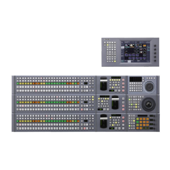
Aux row or even external modules. As the panel is completely customizable at order time, it is important to consult with your Sony account manager and Sales Support Engineer as to the exact panel assembly you purchased before cutting console openings. They can tell you the “assembly number”... - Page 6 As an example, below, these are just a few of the different combinations of modules and sizes of CCP- 8000A control panels. The CCP-6000 series control panel is smaller than the CCP-8000A panel. Instead of being configured module by module, as the CCP-8000A series is, the CCP-6000 series comes as a standard unit. An optional menu display and other modules may be added by the end user at purchase time.
- Page 7 MKS-2700 please use the port marked EDITOR on the MKS-8010B System Control Unit (15-pin to 9-pin adapter is required). Because the MVS system is so configurable, the descriptions above are not exhaustive. If you have any questions regarding your unique system configuration, please contact your Sony Account Manager or Sales Support Engineer. pg. 7...
-
Page 8: After Your Installation
After your Installation… Installation Check-Out Standard to the MVS series is an on-site Installation Check-Out (ICO) by a Sony Field Service Engineer. The amount of on-site time varies, depending on which switcher was purchased and the complexity of the install (for example, was a router interface also purchased?). The typical on-site time is two days. -
Page 9: Operator Training
Operator Training As an option, Sony can supply operator training for your MVS switcher. This training is listed as a line- item option in the switcher quote and, typically, is a 3-day course; however, additional days can be purchased. Sony has a very experienced pool of certified contract trainers who use MVS switchers daily. There are some important guidelines when determining your training schedule: 1. -
Page 10: Section 2: Engineering Quick Start (Hardware)
Please contact your Sony Account Manager for assistance. Your Sony Account Manager can assist you on missing items, if any, and has the ability to bring in other resources, like Sales Support Engineers or Service Engineers, to make your installation go as smoothly as possible. -
Page 11: Unpacking The Boxes
Shotbox™ or a Device Control Module, they will be shipped separately and must be installed by the end user. • CCP-9000 Series panels come as pre-fabricated units in their own boxes. 6. Menu Panel (if purchased) 7. SWC-50xx cables (interconnects between SCU and panel) 8. -
Page 12: Rack Mounting
Ethernet cables. Even though the specification of the maximum distance for a single Ethernet run is 384ft, Sony recommends your single cable-run is no longer than 305 feet. If you need runs longer than that, you may have to convert Ethernet to fiber optic or explore other methods such as repeaters or additional Ethernet switches. -
Page 13: Group And Unit Id Settings
Group and Unit ID settings The MVS family uses fixed IP address, based upon the type of chassis. There are two settings that can be changed by the end user. These are, primarily, to accommodate customers who have multiple switchers on the same LAN or multiple individual chassis as part of the same system (for example 8 channels of MVE-8000A DME will require two DME chassis, which will require different IP addresses.) The two settings are Unit ID and Group ID. -
Page 14: Wiring
“talk” to each other. Simply use a crossover cable or crossover adapter to connect the SCU and DCU “PERIPH” RJ-45 connectors together. If you purchased the Ethernet Switch kit from Sony, you will find a long Ethernet cable, a crossover adapter and a short jumper cable for this purpose. - Page 15 In the above diagram, you can see that the Switcher, DME (if needed) and Panel (really the SCU) all have CNTL and DATA Ethernet cables going to their respective switches. You can also see that the DCU has a crossover cable going to the SCU. pg.
-
Page 16: Switcher Chassis (Mvs-7000X Only)
SWITCHER CHASSIS (MVS-7000X only) pg. 16... -
Page 17: Video Inputs
Video Inputs The MVS-7000X has up to 80 non-looping inputs, each in blocks of 20. These can be seen in the above photo on slots 5-8. All inputs are “mappable” from the control panel menu to any crosspoint button so there is no need to match the physical input to where the operator would like to select it. -
Page 18: Format Converter
DME chassis as a true external device, meaning using primary inputs and outputs. Since this type of wiring is rare, please contact your Sony account manager or Sales Support Engineer if you need assistance. - Page 19 The following shows the backplane of the MVS-7000X’s DME I/O: SLOT 2 (FROM DME) SLOT 3 (TO DME) SIGNAL SIGNAL SIGNAL(DME2) SIGNAL(DME2) (DME1) (DME1) CH1 V Out CH5 V Out CH1 V In CH5 V In CH1 K Out CH5 K Out CH1 K In CH5 K In CH2 V Out...
-
Page 20: Switcher Chassis (Mvs-8000X Only)
SWITCHER CHASSIS (MVS-8000X only) pg. 20... -
Page 21: Video Inputs
Video Inputs The MVS-8000X has up to 164 non-looping inputs, each in blocks of 20 with a couple of exceptions. Each of the backplane input cards has 20 BNC connectors. The 8000X comes standard with 24 inputs. The first 20 of those inputs are found on slot #5. The extra 4 inputs are actually inputs 141-144 and can be found on slot #12. -
Page 22: Mvs-8000X Dedicated M/E Outputs
MVS-8000X Dedicated M/E Outputs In addition to the primary outputs, the MVS-8000X also has, on slot 4, dedicated outputs for each M/E. There are four for each M/E and Program/Preset. These output signals correspond to the first 4 “internal” outputs of each M/E, and are set in the Engineering Setup Menu. By default they are: 1. -
Page 23: Multi-Viewer
In very specific production requirements, it may be desirable to wire the DME chassis as a true external device, meaning using primary inputs and outputs. Since this type of wiring is rare, please contact your Sony account manager or Sales Support Engineer if you need assistance. pg. 23... - Page 24 The following shows the backplane of the MVS-8000X’s DME I/O: SLOT 1 (FROM DME) SLOT 2 (TO DME) SIGNAL SIGNAL SIGNAL(DME2) SIGNAL(DME2) (DME1) (DME1) CH1 V Out CH5 V Out CH1 V In CH5 V In CH1 K Out CH5 K Out CH1 K In CH5 K In CH2 V Out...
-
Page 25: Control Panel
Control Panel Panel Type As mentioned earlier in this guide, the control panel is made up of several parts: The main panel, possibly an aux panel, the menu display, the menu arm and the System Control Unit (SCU). You first need to determine how many sections your main panel has. If your panel is a 4 M/E panel, then it must have a separate Aux row. - Page 26 If your panel is a 3 M/E panel, then the Aux portion can either be “integrated” at the top of the main panel or it can be separated. 3 M/E Panel with Integrated Aux 3 M/E Panel with Separate Aux These panel decisions were made at the time of purchase.
-
Page 27: Connecting The Panel
If you have a 2, or even a 1, M/E panel, then the Aux portion is always “integrated” into the panel. 2 M/E Panel with Integrated Aux Connecting the Panel First make sure the SCU (MKS-8010B) is powered down. Connecting control panel cables or even adding and removing individual panel modules while power is applied can result in blown fuses which are time consuming to replace. -
Page 28: Usb/Memory Stick
the control panel installation manual for a complete description of the MKS-8075A adapter and its mounting options (they can be daisy-chained, connected together, stacked horizontally or vertically, etc). You will notice in the MKS-8075A box there is a small 6-inch SWC cable. This cable is for daisy- chaining the external adapters together (when two or more are purchased) and is not for connecting to the SCU. -
Page 29: Dme Chassis
MENU DISPLAY (15-pin) is a mirror of the touchscreen menu display. This is useful during training to display the menu on a larger screen or projector for all to see. It can also be used in an emergency if a fault develops in the touchscreen. -
Page 30: Parallel Tally
If your manufacturer is not listed, please contact your Sony Account Manager. They can help you find the resources to assist in making your device work properly with your MVS switcher. -
Page 31: Aux Bus Remotes
LAN WIRING. Aux Bus Remotes Sony manufactures two different Aux Bus remote panels for the MVS system: the 1RU MKS-8080 and the 3RU MKS-8082. The 1RU MKS-8080 is typically used for a single aux bus remote. It has 32 small buttons and a jog dial to set which bus is being controlled (and other programming). -
Page 32: After The Install
Each aux remote (up to 16 without an additional controller) is daisy-chained from one to the other with 75-ohm coax video cable. At each end a “T” connector and a 75-ohm terminating resistor must be used. It is also important to set each aux bus remote’s panel ID number before attaching to the chain. Please refer to the specific aux panel’s installation guide on how to install aux bus remotes (including how to set the ID# and wiring) with the switcher system. -
Page 33: Start-Up
Start-up If you have not yet done so, please plug-in and turn on all power supplies on all chassis. Please note that the MVS-8000X switcher chassis requires at least three power supplies to be turned on to operate. The MVS-7000X chassis requires at least two power supplies to be turned on to operate. It will take approximately 30-45 seconds for the control panel to completely light up and about another 2 minutes for the menu display to finish initializing. -
Page 34: Section 3: Engineering Quick Start (Software)
Section 3: Engineering Quick Start (Software) Now that your MVS system is physically installed, this section will get you up and running using the Engineering Setup menu. We will cover basic settings, such as System Format, communication, Video/Key pair assignment and more. The goal in this last section is to make sure all your devices are talking and you can see video going through the switcher and out to a monitor. - Page 35 On the bottom portion of the touchscreen are the individual sections that can be changed for each Group. For instance, on the left, please select the SYSTEM group. You will then see the bottom row change and show you items like NETWORK CONFIG, SYSTEM CONFIG, FORMAT, etc. pg.
-
Page 36: Menu Page Numbers
Menu Page Numbers At the very upper-left corner of the touchscreen you’ll see a box that says “Page” and it will have a 4- digit number. Press the Page button now. You will see a dialog box open. Type 7311 and press ENTER. pg. -
Page 37: Network Config
Network Config This will take you to the ENG SETUP->System->Network Config Menu. We use this menu to make sure everything is talking. This is also where we will see if all our Group and Unit IDs are set correctly. Notice the purple buttons? Purple buttons are “execute” buttons. Most settings in the MVS menu are immediate;... - Page 38 Notice this one shows a single Switcher (SWR1), one panel (PNL1) and one DME (DME1). By the way, DME1 refers to the DME chassis (or in the case of the MVS-7000X for boards in the switcher), it does not refer to the number of channels you purchased. DME1 can have up to 4 channels of video processing. If you have channels 5-8, you should also see DME2.
- Page 39 Pressing DEFINE will say “These are my components and use only these when the system starts.” This keeps the system from trying to, say, talk to PNL2 when there isn’t one. pg. 39...
-
Page 40: Lan Diagnostics
LAN Diagnostics For fun, please press the Page button and enter the following menu page: 7431. This will take you to the DIAG->System Info->LAN Status menu. This graphically shows the communication between the components you just defined. Just as a side note, blinking red lines are bad and mean communication is not occurring. - Page 41 You can immediately go to the current error status by touching the word ERROR on the screen. This error status shows that DCU1 and DCU2 are missing reference. Please be sure to keep the ERROR POPUP button on. Turning it off will prevent the error notification from being displayed. pg.
-
Page 42: System Config
System Config Now that we’ve told MVS what it’s supposed to be looking for, let’s continue to make sure all the parts of the system will talk correctly. Please go to menu page 7312. This takes us to ENG SETUP->SYSTEM- >SYSTEM CONFIG. - Page 43 Likely, the only item we need to check is DME assignments and FM LAN. Please press the grey solid button labeled “SWITCHER ASSIGN” (grey solid buttons are either shortcut buttons that take you to another menu or sub-menu buttons). You can also just enter menu page 7312.2 (the decimal denotes a submenu).
-
Page 44: Signal Format
It is beyond the scope of this document to setup a complex system with multiple panels and/or switcher processors. If your system is more complex than a standard one processor, one panel please contact your Sony Account Manager and they will put you in touch with someone that can help configure more complex systems. - Page 45 Please select the video format you will use (which will likely be 480i/59.94, 720p/59.94 or 1080i/59.94. If the only formats available to you are 576i/50 and 480i/59.94 (and you need HD) then it is likely your Multi-format license keys have not been installed. Please contact your Sony Account Manager for pg. 45...
- Page 46 You will see that if it was necessary to change the format, the column marked “Signal Format” is in yellow. This means you’ve selected it, but not executed it. Don’t execute yet, we’re not finished! At the bottom of the menu is a group box titled “Ref Input Format”. This is where you need to set whether you are using Black Burst (recommended) or Tri-Level sync.
- Page 47 At this point, if you made any signal format changes (some items will be in yellow), press the EXECUTE button to save those changes. It will warn you that the system will restart. This is normal. Please say OK. When the system comes back up, we should be in the correct operating format. To check, go back to menu 7313 and see if everything is set to the correct format and reference type.
-
Page 48: Format Converters
Format Converters If you have format converter cards, we need to now set their input and output formats. If you have a MVS-8000X you can have up to two format converter cards. The MVS-7000X supports a single format converter board. The system will recognize how many cards you have and, in the right column, you will see Input1-4, Input5-8 (and if you have two boards) Input9-12 and Input13-16. -
Page 49: Software Versions
If you ever have trouble and call Sony Service on the phone, one of the first things they’ll ask you is what software version you have installed on each component. By the way, it’s common to have mis-matched software versions between different switcher components. -
Page 50: Mvs-7000X Flexconfig
MVS-7000X FlexConfig The MVS-7000X can have up to 3 physical M/E boards in its chassis. Each of those M/E boards has 8 keyers. Exclusive to the MVS-7000X is a feature called FlexConfig, which allows the logical partitioning of those physical M/E boards and keyers. First, you need to find out exactly how many physical M/E boards were purchased in your switcher, and you also need to look at the number of M/E banks on the control panel. - Page 51 In this mode, P/P and M/E 1 have 8 keyers, but M/E 2 and M/E 3 will have 4 keyers each. It is very likely the assignment of these resources as already been discussed between Sony, your engineering management and your facilities switcher operators.
- Page 52 The example above shows having only two physical boards installed in the chassis but having a 4 M/E control panel. In this case, each of the available boards has been divided into two logical M/E partitions. Each M/E in this scenario will have 4 keyers. pg.
-
Page 53: A Note On Using 8 Keyers
A Note on using 8 Keyers Sony control panels, by default, are shipped from the factory programmed and labeled for four keyers per M/E. If you are running any M/E’s that have 8 keyers you will not be able to control keys 5-8 until the switcher is properly programmed and the panel’s button labels have been updated. -
Page 54: Outputs
Outputs The next setup item we need to configure are the OUTPUTS. Why outputs before inputs? Well, we need to see a working output on a monitor to see if we have working inputs. Please go to menu page 7333 (ENG SETUP->SWITCHER->OUTPUT. In the table, you can see what has, by default, been assigned to each output connector on the back of the switcher. - Page 55 You can see now we have two tables. Notice the Arrow in the middle between the two tables. This type of “flow” is repeated all over the MVS menu. It’s simply saying that whatever you choose on the right table will make its way into the left table. In this case, the right table as all the sources that can be assigned to a physical output.
-
Page 56: Inputs
Notice there is no limit to how many times I can route the same signal to different outputs – with one exception. Aux buses can only be routed to one output at a time. In other words, it’s not possible to have Aux 1 on both Out 10 and Out 11 at the same time. -
Page 57: Naming Inputs
Naming Inputs First things first. Let’s name the inputs. It will make things far easier later. Please press the “Src Name/LCD Color” button which will take use to menu 7322.6. This table represents all the inputs, both physical and other sources in the switcher like Frame Memory outputs. Select your first input you’d like to label and press the “Source Name”... -
Page 58: Video/Key And Table Assignments
end digit. If you have 15 cameras, you’ll have to do CAM1-9, then do it again this time start with “CAM|10” and it will auto-name CAM 11-15. • If a source has two characters or less, the display will show very large text. This is handy when you want to identify a camera as just “1”... -
Page 59: Key Signals
a 8000X you’ll find inputs 1-144, if it’s a 7000X you’re find inputs 1-80). But you’ll also find a lot of other items like Color BKGD 1 and 2. You’ll also find BLACK and WHITE (we’ll get to WHITE later). If you have a 8000X, the Premium Inputs will be listed. - Page 60 the keyer, we have to be a bit tidier. We need to assign a full field white key signal to any video source that doesn’t specifically have an associated key signal. Pick an item from the left table that isn’t going to have a dedicated key signal (like a camera) and perform the same procedure as above, except this time look for the source WHITE in the right table (as of software version 12, it is source 90).
-
Page 61: Sub-Tables
Sub-Tables The left table is a list of all the parts of the switcher that can have crosspoint tables assigned. Typically they are all going to be set the same. If this is a factory default, then they are all likely set to MAIN (that’s the second column on the left table). -
Page 62: Table Copy
Let’s set the whole switcher to use TABLE1. Please press the small “ALL” Button right below the left table. The entire table will now be highlighted. Next, on the right table, please select Table1. Finally press the purple “TABLE ASSIGN SET” button. Now, the entire switcher is using Table1 for mapping. - Page 63 This has made Table1 exactly the same as Main. Now, let’s change Table 1’s button assignments. This lets the operator move inputs to any crosspoint button, but preserves your engineering settings in the MAIN V/K assign table. pg. 63...
-
Page 64: A Word Of Caution
Table Button Assign Please jump back to menu 7322 and select Table Button Assign. This screen looks a lot like the MAIN table assign. First, be sure knob #1 is set to “Table 1”, since that’s what we’re using everywhere. The left table represents the actual buttons on the switcher panel. -
Page 65: Let's Try This Out
6pm news that will call up CAM1 (which is currently on button 10). All Sub-Tables reference the MAIN V/K pair number! If the MAIN V/K pair is changed later to be Input 5 instead of Input 1 (where it was originally set), there will be a big on-air problem. -
Page 66: Using The Multi-Viewer
Using the Multi-Viewer As mentioned earlier, the MVS-X series comes with either one or two multi-viewers, depending on how many output boards were purchased. If you would like to use the multi-viewer now instead of setting up several monitors for testing, please read on. On the back of the switcher chassis, the multi-viewer outputs are called MSD1 and MSD2. - Page 67 To set what is actually going to each window, please press “Output Assign.” Here, you can select the output on the right and assign it to a specific Multi-Viewer window on the left by pressing the SET button. Window numbers are sequential from the upper-left of the screen to the lower-right.
-
Page 68: Using The Internal Format Converters
Using the internal Format Converters If you have purchased the internal format converters for your switcher and would like to set them up, please follow this section; otherwise please skip down to “Saving Our Work”. We have already set the type of input(s) the FCs will be expecting earlier in this document. - Page 69 Here you can select which physical BNC input is assigned to a format converter input channel. Then, mapping a format converter’s input to a V/K pair and a crosspoint button are exactly the same procedures as we covered earlier. pg. 69...
-
Page 70: Format Converter Parameters
The only difference is the source number. On the 7000X, the format converter inputs are found on source # 81-88. So, using the same mapping procedures, make a Main V/K pair, except this time use a FC input. Format Converter Parameters On both the 7000X and 8000X, you can change different parameters on the format converter inputs, such as the type of signal (is it 4:3, 16:9, letterbox) and make small tweaks such as edge enhancement. - Page 71 It is important to note that the routing of the signal fed to the format converter output is shared with non-converted signals. Take a look at menu 7333.1 (switcher output assign). You can see here that FC output #1 will be assigned the same signal as physical output #1. Format Converter output #2 will be assigned the same signal as physical output #2.
-
Page 72: Saving Our Work
Saving Our Work Now that we’ve gone to all this trouble to set up and program a small part of the switcher, we need to do a couple more things. First, we need to save what we’ve done to non-volatile memory and tell the switcher to come up this way every time. -
Page 73: Setup Define
After you execute the changes, the top table should show the proper boot modes. Setup Define We have told the switcher how to boot but we actually haven’t told the switcher what to boot with. For this we need to press SETUP DEFINE on each component. pg. -
Page 74: Saving To Disk
You might also like to save a disk file as well. Please go to menu page 7171 (FILE->Configure->Directory). Let’s make a new folder on the internal hard drive. Press the NEW button and create a folder (8 character maximum folder name). Let’s call it “Sony” pg. 74... - Page 75 Next, jump to menu page 7161. Inside the “category” group, please make sure the only button that is turned on is “Setup”. This indicates that when we save the file, only setup data will be saved (no effects or any other operator file types will be saved).
- Page 76 Make sure “Register” is showing on the “Device” pushbutton on the upper left. Make sure “HDD” is showing under “Device” on the right. pg. 76...
- Page 77 On the right, press the pushbutton under “Directory”. A popup will appear. Select the folder name you just made (“Sony”). pg. 77...
- Page 78 After the popup disappears, press the SAVE purple button. The right-pointing arrow over the word SAVE indicates you will be saving data from “Register” (the switcher) to the HDD in the sub-folder. You have now successfully saved both the flash memory of the switcher and also created an offline version on the internal hard drive.
-
Page 79: That's It
30 days’ notice and it’s strongly recommended that you don’t schedule your ICO and your operator training back-to-back, in case there’s an issue that needs resolving. If you have any questions or just need an extra hand, please contact your Sony Account Manager. They will find the right person to assist you.