Sign In
Upload
Manuals
Brands
VIA Technologies Manuals
Motherboard
EPIA-P910
VIA Technologies EPIA-P910 Manuals
Manuals and User Guides for VIA Technologies EPIA-P910. We have
3
VIA Technologies EPIA-P910 manuals available for free PDF download: User Manual
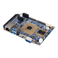
VIA Technologies EPIA-P910 User Manual (67 pages)
Highly-integrated low-power platform with rich multimedia and I/O capabilities
Brand:
VIA Technologies
| Category:
Motherboard
| Size: 3.87 MB
Table of Contents
Table of Contents
5
1 Product Overview
11
Key Features and Benefits
11
VIA Eden ® X4 Processor
11
VIA VX11H MSP Chipset
11
Expansion Option
11
Product Specifications
12
Layout Diagram
14
Figure 1: Layout Diagram of the VIA EPIA-P910 (Top and Bottom Side)
14
Table 1: Layout Description Table of the VIA EPIA-P910
14
Product Dimensions
15
Figure 2: Mounting Holes and Dimensions of the VIA EPIA-P910
15
Height Distribution
16
Figure 3: Height Distribution of the VIA EPIA-P910
16
2 I/O Interface
17
External I/O Ports
17
Figure 4: Back Panel I/O Ports
17
Table 2: Layout Description Table of the Back Panel I/O Ports
17
Figure 5: Gigabit Ethernet Port Diagram
18
Figure 6: USB 3.0 Port Diagram
18
Gigabit Ethernet Port
18
Table 3: Gigabit Ethernet Port Pinouts
18
Table 4: Gigabit Ethernet LED Color Definition
18
Table 5: USB 3.0 Port Pinouts
18
USB 3.0 Port
18
Figure 7: Mini HDMI Port Diagram
19
Figure 8: VGA Port Diagram
19
Mini HDMI ® Port
19
Table 6: Mini HDMI Port Pinouts
19
Table 7: VGA Port Pinouts
19
VGA Port
19
Onboard I/O
20
LVDS Panel Connector
20
Figure 9: LVDS Panel Connector Diagram
20
Table 8: LVDS Panel Connector Pinouts
20
SATA Connectors
21
Figure 10: SATA Connectors Diagram
21
Table 9: SATA Connectors Pinouts
21
SATA Power Connector
22
Figure 11: SATA Power Connector Diagram
22
Table 10: SATA Power Connector Pinouts
22
Kb/Ms/Lpc/Gpio/Smbus Combination Pin Header
23
Figure 12: KB/MS/LPC/GPIO/ Smbus Combination Pin Header Diagram
23
Table 11: Kb/Ms/Lpc/Gpio/Smbus Combination Pin Header Pinouts
23
USB 2.0/Front Panel/Audio Combination Pin Header
24
Figure 13: USB 2.0/Front Panel/Audio Combination Pin Header Diagram
24
Table 12: USB 2.0/Front Panel/Audio Combination Pin Header Pinouts
24
System/Cpu Fan Connector
25
DC-In Power Connector
25
Figure 14: System/Cpu Fan Connector Diagram
25
Figure 15: DC-In Power Connector Diagram
25
Table 13: System/Cpu Fan Connector Pinouts
25
Table 14: DC-In Power Connector Pinouts
25
CMOS Battery Connector
26
SPI Flash Connector
26
Figure 16: CMOS Battery Connector Diagram
26
Figure 17: SPI Flash Connector Diagram
26
Table 15: CMOS Battery Connector Pinouts
26
Table 16: SPI Flash Connector Pinouts
26
3 Jumpers
27
Figure 18: Jumper Settings Example
27
Clear CMOS Jumper
28
Figure 19: Clear CMOS Jumper Diagram
28
Table 17: Clear CMOS Jumper Settings
28
Backlight Power Jumper
29
LVDS Panel Power Jumper
29
Figure 20: Backlight Power Jumper Diagram
29
Figure 21: LVDS Panel Power Jumper Diagram
29
Table 18: Backlight Power Jumper Settings
29
Table 19: LVDS Panel Power Jumper Settings
29
4 Expansion Slots
30
High Speed Extension Slot
30
Figure 22: High Speed Extension Slot Diagram
30
Table 20: High Speed Extension Slot Pinouts
31
DDR3 SODIMM Memory Slot
32
Installing a Memory Module
32
Figure 23: DDR3 SODIMM Memory Slot Diagram
32
Figure 24: Inserting the Memory Module
32
Figure 25: Locking the Memory Module
33
Figure 26: Installing the Memory Thermal Pad
33
Removing a Memory Module
34
Figure 27: Disengaging the SODIMM Locking Clasps
34
Figure 28: Removing the Memory Module
34
5 Hardware Installation
35
Installing the VIA EPIA-P910-A I/O Expansion Card
35
Figure 29: Connecting the VIA EPIA-P910-A I/O Expansion Card
35
Installing into a Chassis
36
Suggested Minimum Chassis Dimensions
36
Suggested Minimum Chassis Height
36
Figure 30: Suggested Minimum Chassis Dimensions
36
Figure 31: Suggested Minimum Internal Chassis Ceiling Height
36
Suggested Keepout Areas
37
Figure 32: Suggested Keepout Areas
37
6 BIOS Setup Utility
38
Entering the BIOS Setup Utility
38
Control Keys
38
Getting Help
38
System Overview
39
BIOS Information
39
Memory Information
39
System Language
39
System Date
39
System Time
39
Figure 33: Illustration of the Main Menu Screen
39
Advanced Settings
40
Figure 34: Illustration of the Advanced Settings Screen
40
ACPI Settings
41
Enable Hibernation
41
ACPI Sleep State
41
Figure 35: Illustration of the ACPI Settings Screen
41
S5 RTC Wake Settings
42
Wake System with Fixed Time
42
Wake System with Dynamic Time
42
Figure 36: Illustration of the S5 RTC Wake Settings Screen
42
CPU Configuration
43
Tm3
43
Figure 37: Illustration of CPU Configuration Screen
43
SATA Configuration
44
SATA Mode
44
Figure 38: Illustration of SATA Configuration Screen
44
PC Health Status
45
Fan Turbo Mode
45
Figure 39: Illustration of PC Health Status Screen
45
Clock Generator Configuration
46
CPU Spread Spectrum
46
Pcie Spread Spectrum
46
Figure 40: Illustration of Clock Generator Configuration Screen
46
Onboard Device Configuration
47
Onboard LAN Enable
47
Eup/Erp Lot6 Support
47
S5 Wakeup on LAN
47
1CH LVDS Backlight Control
47
Figure 41: Illustration of Onboard Device Configuration Screen
47
Chipset Settings
48
Figure 42: Illustration of Chipset Settings Screen
48
DRAM Configuration
49
DRAM Clock
49
VGA Share Memory (Frame Buffer)
49
Figure 43: Illustration of DRAM Configuration Screen
49
Video Configuration
50
Select Display Device Control
50
Select Display Device 1 and 2
50
Panel Type
50
Figure 44: Illustration of Video Configuration Screen
50
Panel Type2
51
PMU_ACPI Configuration
52
Other Control
52
Figure 45: Illustration of PMU_ACPI Configuration Screen
52
Figure 46: Illustration of Other Control Screen
52
AC Loss Auto-Restart
53
USB S4 Wakeup
53
SDIO_CR Configuration
54
SDIO Host Controller
54
SDIO Specification Ver3.0 Support
54
Voltage Support 1.8V
54
High Speed Support
54
Driver Type Select
54
SDR50 Support
54
SDR104 Support
54
DDR50 Support
54
SDR50 Tuning Enable
54
Timer Count for Re-Tuning
55
Card Reader Host Controller 0
55
Others Configuration
56
WATCHDOG Timer Enable
56
Keyboard/Mouse Wakeup Control
56
Figure 48: Illustration of Others Configuration Screen
56
Boot Settings
57
Boot Configuration
57
Quiet Boot
57
Boot Option Priorities
57
Launch PXE Oprom Policy
57
Figure 49: Illustration of Boot Settings Screen
57
Save & Exit
58
Save Changes and Exit
58
Discard Changes and Exit
58
Save Changes and Reset
58
Discard Changes and Reset
58
Save Options
58
Save Changes
58
Discard Changes
58
Figure 50: Illustration of Save & Exit Screen
58
Restore Defaults
59
7 Software and Technical Support
60
Microsoft and Linux Support
60
Driver Installation
60
Technical Support and Assistance
60
Appendix A. Installing Wireless Accessories
61
Installing the VIA EMIO-1533 USB Wi-Fi Module
61
Figure 51: Installing the VIA EMIO-1533 Module to the Chassis
61
Figure 52: Connecting the USB Wi-Fi Cable (VIA EMIO-1533)
61
Figure 53: Installing the Wi-Fi Antenna Cable (VIA EMIO-1533)
62
Figure 54: Connecting the Wi-Fi Antenna Cable to the VIA EMIO-1533 Module
62
Installing the VIA EMIO-5531 USB Wi-Fi & Bluetooth Module
63
Figure 55: Installing the VIA EMIO-5531 Module to the Chassis
63
Figure 56: Connecting the USB Wi-Fi Cable (VIA EMIO-5531)
63
Appendix B. Pin Header and Connector Vendors List
65
Table 21: VIA EPIA-P910 Pin Header and Connector Vendors List
65
Appendix C. Power Consumption Report
66
Epia-P910-12Qe
66
Burn-In 3Dmark06, 1920X1080 (Demo Mode)
66
Passmark Burn-In (CPU Usage = 100%)
66
Power DVD 10.0 to Player H.264 1080P Movie (Enable H/W Acceleration)
66
Idle at Windows 7 X64
66
Advertisement
VIA Technologies EPIA-P910 User Manual (88 pages)
Pico-ITX embedded board
Brand:
VIA Technologies
| Category:
Motherboard
| Size: 4.88 MB
Table of Contents
Regulatory Compliance
2
Safety Precautions
3
Table of Contents
5
1 Product Overview Product Overview
12
Key Features and Benefits
13
VIA Eden X4 Processor
13
VIA VX11H MSP Chipset
13
Expansion Option
13
Product Specifications
15
Layout Diagram
18
Product Dimensions
20
Height Distribution
21
2 I/O Interface
22
External I/O Ports
22
LAN Port: Gigabit Ethernet
23
USB 3.0 Port
24
Mini HDMI ® Port
25
VGA Port
26
Onboard Connectors
27
LVDS Connector
27
SATA Connectors
29
SATA Power Connector
30
Kb/Ms/Lpc/Gpio/Smbus Combination Pin Header
31
Audio + USB 2.0 + Front Panel Combination Pin Header
33
System/Cpu Fan Connector
35
DC-In Power Connector
36
CMOS Battery Connector
37
SPI Flash Connector
38
3 Jumpers
39
Clear CMOS Jumper
39
Backlight Power Select Jumper
41
Panel Power Control Jumper
42
Expansion Slots Expansion Slots
43
Expansion Slots
43
High Speed Extension Slot
43
DDR3 SODIMM Memory Slot
46
Installing a Memory Module
47
Removing a Memory Module
49
Hardware Installation
50
Installing the P910-A Companion Card (Optional)
50
Installing into a Chassis
51
Suggested Minimum Chassis Dimensions
51
Suggested Minimum Chassis Height
52
Suggested Keepout Areas
53
BIOS Setup Utility BIOS Setup Utility
54
BIOS Setup Utility
54
Entering the BIOS Setup Utility
54
Control Keys
54
Getting Help
55
System Overview
56
BIOS Information
56
Memory Information
56
System Language
56
System Date
57
System Time
57
Advanced Settings
58
ACPI Settings
59
S5 RTC Wake Settings
60
CPU Configuration
61
SATA Configuration
62
PC Health Status
63
Clock Generator Configuration
64
Onboard Device Configuration
65
Chipset Settings
67
DRAM Configuration
68
Video Configuration
70
PMU_ACPI Configuration
72
SDIO_CR Configuration
74
Others Configuration
76
Boot Settings
77
Boot Configuration
77
Boot Option Priorities
78
Save & Exit
79
Save Changes and Exit
79
Discard Changes and Exit
79
Save Changes and Reset
79
Discard Changes and Reset
80
Save Options
80
Save Changes
80
Discard Changes
80
Restore Defaults
80
Driver Installation Driver Installation
81
Driver Installation
81
Microsoft Driver Support
81
Linux Driver Support
81
Appendix A. Power Consumption Report
82
Epia-P910-10Q
82
Burn-In 3Dmark06, 1280 X 1024 (Demo Mode) Quad Core 1.0+Ghz
83
[Enable PMON]
83
Burn-In 3Dmark06, 1280 X 1024 (Demo Mode) Quad Core 1.0+Ghz [Disable PMON]
83
Passmark Burn-In (CPU Usage = 100%) Quad Core 1.0+Ghz [Enable
83
Passmark Burn-In (CPU Usage = 100%) Quad Core 1.0+Ghz [Disable PMON]
83
A.1.1. Burn-In 3Dmark06, 1280 X 1024 (Demo Mode) Quad Core 1.0+Ghz Enable PMON]
83
Power DVD 10.0 to Player H.264 1080P Movie Quad Core 1.0+Ghz [Enable PMON] Enable H/W Acceleration
84
Power DVD 10.0 to Player H.264 1080P Movie Quad Core 1.0+Ghz [Disable PMON] Enable H/W Acceleration
84
Power DVD 10.0 to Player MPEG2 1080P Movie Quad Core 1.0+Ghz [Enable PMON] Enable H/W Acceleration
84
Power DVD 10.0 to Player MPEG2 1080P Movie Quad Core 1.0+Ghz [Disable PMON] Enable H/W Acceleration
85
Idle at Windows 7 X64 Quad Core 1.0+Ghz [Enable PMON]
85
Idle at Windows 7 X64 Quad Core 1.0+Ghz [Disable PMON]
85
Suspend S1 Quad Core 1.0+Ghz [Enable PMON]
86
Suspend S1 Quad Core 1.0+Ghz [Disable PMON]
86
Ader and Connector Vendor Lists
87
EPIA-P910 Mainboard
87
VIA Technologies EPIA-P910 User Manual (20 pages)
Pico-ITX embedded board
Brand:
VIA Technologies
| Category:
Industrial PC
| Size: 0.43 MB
Table of Contents
Table of Contents
5
Product Overview Product Overview
9
Product Overview
9
Key Features and Benefits
9
VIA Eden X4 Processor
9
VIA VX11H MSP Chipset
9
Expansion Option
9
Product Specifications
10
Layout Diagram
12
Dimensions
14
Height Distribution
15
I/O Interface I/O Interface
16
External I/O Ports
16
Gigabit Ethernet Port
16
USB 3.0 Port
17
Mini HDMI ® Port
17
VGA Connector
18
Onboard Connectors
19
LVDS Connector
19
SATA Connectors
20
Advertisement
Advertisement
Related Products
VIA Technologies EPIA-P900
VIA Technologies EPIA-PX5000EG - VIA Motherboard - Pico ITX
VIA Technologies EPIA-PX10000G - VIA Motherboard - Pico ITX
VIA Technologies EPIA-PE
VIA Technologies EPIA-PX
VIA Technologies EPIA-PN
VIA Technologies EPIA-P710
VIA Technologies EPIA-P820
VIA Technologies EPIA-P710-10
VIA Technologies 10GMU20600020
VIA Technologies Categories
Motherboard
Computer Hardware
Desktop
Control Unit
Industrial PC
More VIA Technologies Manuals
Login
Sign In
OR
Sign in with Facebook
Sign in with Google
Upload manual
Upload from disk
Upload from URL