
Related Manuals for VIA Technologies EPIA-P910


Summary of Contents for VIA Technologies EPIA-P910
- Page 1 USER MANUAL VIA EPIA-P910 Highly-integrated low-power platform with rich multimedia and I/O capabilities 2.05-07022020-154800...
- Page 2 VIA Technologies, Inc. reserves the right the make changes to the products described in this manual at any time without prior notice. Regulatory Compliance FCC-A Radio Frequency Interference Statement This equipment has been tested and found to comply with the limits for a class A digital device, pursuant to part 15 of the FCC rules.
- Page 3 Battery Recycling and Disposal Only use the appropriate battery specified for this product. Do not re-use, recharge, or reheat an old battery. Do not attempt to force open the battery. Do not discard used batteries with regular trash. ...
- Page 4 VIA EPIA-P910 User Manual Box Contents 1 x VIA EPIA-P910 board 1 x SATA cable 1 x SATA power cable 1 x DC power cable Ordering Information Model Name Description ® EPIA-P910-12QE Pico-ITX board with 1.2GHz VIA Eden X4 CPU, Mini HDMI, VGA, LVDS, 2 x USB 3.0, 6 x USB 2.0, Gigabit Ethernet, 2 x SATA and 12V DC-in...
-
Page 5: Table Of Contents
Installing a Memory Module ......................... 22 4.2.2. Removing a Memory Module ........................ 24 5. Hardware Installation ....................... 25 5.1. Installing the VIA EPIA-P910-A I/O Expansion Card ................25 5.2. Installing into a Chassis ..........................26 5.2.1. Suggested minimum chassis dimensions .................... 26 5.2.2. - Page 6 VIA EPIA-P910 User Manual 6.5.1.1. Enable Hibernation ........................31 6.5.1.2. ACPI Sleep State ..........................31 6.5.2. S5 RTC Wake Settings ..........................32 6.5.2.1. Wake system with Fixed Time ....................32 6.5.2.2. Wake system with Dynamic Time ....................32 6.5.3. CPU Configuration ........................... 33 6.5.3.1.
- Page 7 VIA EPIA-P910 User Manual 6.8.7. Discard Changes ............................48 6.8.8. Restore Defaults ............................49 7. Software and Technical Support .................... 50 7.1. Microsoft and Linux Support ........................50 7.1.1. Driver Installation ............................. 50 7.2. Technical Support and Assistance ......................50 Appendix A.
- Page 8 VIA EPIA-P910 User Manual List of Figures Figure 1: Layout diagram of the VIA EPIA-P910 (top and bottom side) ..............4 Figure 2: Mounting holes and dimensions of the VIA EPIA-P910 ................5 Figure 3: Height distribution of the VIA EPIA-P910 ......................6 Figure 4: Back panel I/O ports............................7...
- Page 9 VIA EPIA-P910 User Manual Figure 57: Installing the Wi-Fi antenna cable (VIA EMIO-5531) ................54 Figure 58: Connecting the Wi-Fi antenna cable to the VIA EMIO-5531 module ..........54...
- Page 10 Table 17: Clear CMOS jumper settings ........................18 Table 18: Backlight power jumper settings ........................ 19 Table 19: LVDS panel power jumper settings ......................19 Table 20: High Speed Extension slot pinouts ......................21 Table 21: VIA EPIA-P910 pin header and connector vendors list ................. 55...
-
Page 11: Product Overview
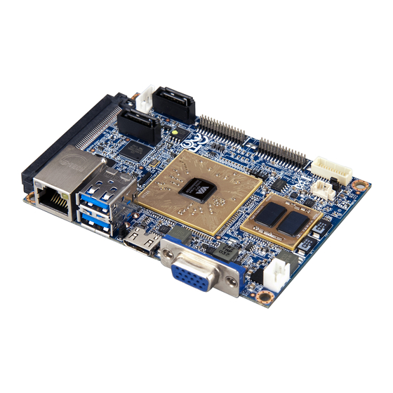
Based on the Pico-ITX form factor measuring just 10cm x 7.2cm, the VIA EPIA-P910 comes with a rich set of I/O and connectivity features, including two USB 3.0 ports, one Gigabit Ethernet port, one Mini HDMI port, and one VGA port. -
Page 12: Product Specifications
VIA EPIA-P910 User Manual 1.2. Product Specifications Processor ® 1.2GHz VIA Eden X4 (Fanless) Chipset VIA VX11H MSP Graphics Integrated VIA C-640 DX11 3D/2D graphics and video processor MPEG-2, WMV9, VC-1, and H.264 Full HD video decoder ... - Page 13 VIA EPIA-P910 User Manual Supported Operating System Windows 10 Windows 8.1 Windows 8 Windows 7 Windows Embedded Standard 7 Linux System Monitoring & Management Wake-on-LAN Keyboard-Power-on Timer-Power-on System Power Management ...
-
Page 14: Layout Diagram
VIA EPIA-P910 User Manual 1.3. Layout Diagram Figure 1: Layout diagram of the VIA EPIA-P910 (top and bottom side) Item Description JM1: Clear CMOS jumper CN3: High Speed Extension slot SATA2: SATA connector 2 PWR2: SATA power connector SATA1: SATA connector 1 CN2: Audio+USB 2.0+Front Panel combination pin header... -
Page 15: Product Dimensions
VIA EPIA-P910 User Manual 1.4. Product Dimensions Figure 2: Mounting holes and dimensions of the VIA EPIA-P910... -
Page 16: Height Distribution
VIA EPIA-P910 User Manual 1.5. Height Distribution Figure 3: Height distribution of the VIA EPIA-P910... -
Page 17: I/O Interface
VIA EPIA-P910 User Manual 2. I/O Interface The VIA EPIA-P910 has a wide selection of interfaces. It includes a selection of frequently used ports as part of the external I/O coastline. 2.1. External I/O Ports Figure 4: Back panel I/O ports... -
Page 18: Gigabit Ethernet Port
2.1.2. USB 3.0 Port The VIA EPIA-P910 is equipped with two USB 3.0 ports. Each USB 3.0 port has a maximum data transfer rate of up to 5Gb/s and is backwards compatible with the USB 2.0 specification. The USB 3.0 ports provides complete Plug and Play and hot swap capabilities for external devices. -
Page 19: Mini Hdmi ® Port
VIA EPIA-P910 User Manual 2.1.3. Mini HDMI ® Port ® ® The integrated 19-pin mini HDMI port uses an HDMI Type C connector as defined in the HDMI specification. The mini HDMI port is for connecting to HDMI ® displays. The pinouts of the mini HDMI port are shown below. -
Page 20: Onboard I/O
2.2. Onboard I/O 2.2.1. LVDS Panel Connector The VIA EPIA-P910 has one 24-pin LVDS panel connector. The LVDS panel connector connects the panel’s LVDS cable to support the single-channel 18-bit/24-bit display. Backlight controls are integrated into the LVDS panel connector pinout. The LVDS panel connector is labeled as “LVDS1”. The pinouts of the connector are shown below. -
Page 21: Sata Connectors
VIA EPIA-P910 User Manual 2.2.2. SATA Connectors The two SATA connectors onboard can support up to 3Gbps transfer speeds. Both SATA connectors have a 7th pin that can provide +5V power to a SATA Disk-on-Module (DOM). When a regular SATA hard drive is connected, the 7th pin will be a ground pin. -
Page 22: Sata Power Connector
VIA EPIA-P910 User Manual 2.2.3. SATA Power Connector The SATA power connector provides both +5V and +12V directly through the board to the SATA drives. The SATA power connector is labeled as “PWR2”. The pinouts of the SATA power connector are shown below. -
Page 23: Kb/Ms/Lpc/Gpio/Smbus Combination Pin Header
VIA EPIA-P910 User Manual 2.2.4. KB/MS/LPC/GPIO/SMBus Combination Pin Header The VIA EPIA-P910 includes one KB, MS, LPC, GPIO, and SMBus combination pin header block labeled as “CN1”. The combination pin header is for connecting KB, MS, LPC, GPIO, and SMBus devices. The pinouts of the pin header are shown below. -
Page 24: Usb 2.0/Front Panel/Audio Combination Pin Header
2.2.5. USB 2.0/Front Panel/Audio Combination Pin Header The VIA EPIA-P910 includes one USB 2.0, Front Panel and Audio combination pin header block labeled as “CN2”.The USB 2.0, front panel and audio combination pin header is used to enable up to three USB 2.0 ports and to connect the power switch, reset switch, power LED, suspend LED, HDD LED, case speaker, S/PDIF out, Line-out, Line-in and Mic-in jacks. -
Page 25: System/Cpu Fan Connector
Table 13: System/CPU fan connector pinouts 2.2.7. DC-in Power Connector The VIA EPIA-P910 has an onboard DC-in 2-pin power connector to connect the DC-in power cable. The DC-in power connector is labeled as “PWR1”. The pinouts of the DC-in power connector are shown below. -
Page 26: Cmos Battery Connector
Table 15: CMOS battery connector pinouts 2.2.9. SPI Flash Connector The VIA EPIA-P910 has one 8-pin SPI flash connector. The SPI (Serial Peripheral Interface) flash connector is used to connect to the SPI BIOS programming fixture for updating the SPI flash ROM. The connector is labeled as “J1”. -
Page 27: Jumpers
VIA EPIA-P910 User Manual 3. Jumpers This section will explain how to configure the VIA EPIA-P910 to match the needs of your application by setting the jumpers. Jumper Description A jumper consists of a pair conductive pins used to close in or bypass an electronic circuit to set up or configure a particular feature using a jumper cap. -
Page 28: Clear Cmos Jumper
VIA EPIA-P910 User Manual 3.1. Clear CMOS Jumper The VIA EPIA-P910 comes with a Clear CMOS jumper The onboard CMOS RAM stores system configuration data and has an onboard battery power supply. To reset the CMOS settings, set the jumper on pins 2 and 3 while the system is off, then return the jumper to pins 1 and 2 afterwards. -
Page 29: Backlight Power Jumper
VIA EPIA-P910 User Manual 3.2. Backlight Power Jumper The VIA EPIA-P910 has a jumper that controls the input voltage delivered to the LVDS inverter connector. The jumper is labeled as “JM2”. The jumper settings are shown below. Figure 20: Backlight power jumper diagram... -
Page 30: Expansion Slots
VIA EPIA-P910 User Manual 4. Expansion Slots 4.1. High Speed Extension Slot The board-to-board slot labeled as “CN3” is a combination connector reserved for connecting to a customized expansion card. The slot pinout supports PCIe, LAN, USB 2.0, Audio, SDIO and SIM. -
Page 31: Table 20: High Speed Extension Slot Pinouts
VIA EPIA-P910 User Manual SMBDT DVP1VS SMBCK DVP1D11 -PEREQ1 DVP1D10 -PEXWAKE DVP1D9 -PEX4RST DVP1D8 -PEX2RST DVP1D7 -PEX1RST DVP1D6 DVP1D5 USBHP3- DVP1D4 USBHP3+ DVP1D3 DVP1D2 PEXRX2+ DVP1D1 PEXRX2- DVP1D0 PETN2 USBHP4- PETP2 USBHP4+ PE6CLK- USBHP2- PE6CLK+ USBHP2+ PEXRX0- PEXRX4- PEXRX0+ PEXRX4+... -
Page 32: Ddr3 Sodimm Memory Slot
VIA EPIA-P910 User Manual 4.2. DDR3 SODIMM Memory Slot The VIA EPIA-P910 provides one 204-pin DDR3 SODIMM slot that supports non-ECC DDR3 1600/1333/1066 SODIMM memory modules. The memory slot can accommodate up to 8GB of DDR3 1600/1333/1066 memory. The memory slot is labeled as “SODIMM1”. The location of the DDR3 memory slot is shown below. -
Page 33: Figure 25: Locking The Memory Module
VIA EPIA-P910 User Manual Step 2 Push down the SODIMM memory module until the locking clasps lock the module into place. There will be a slight tension as the SODIMM memory module is being locked. Figure 25: Locking the memory module Step 3 Install the memory thermal pad on the top of the SODIMM memory module. -
Page 34: Removing A Memory Module
VIA EPIA-P910 User Manual 4.2.2. Removing a Memory Module Step 1 To disengage the locking clasps, push the locking clasps horizontally outward away from the SODIMM memory module. Figure 27: Disengaging the SODIMM locking clasps Step 2 When the locking clasps have cleared, the SODIMM memory module will automatically pop up. Remove the memory module. -
Page 35: Hardware Installation
VIA EPIA-P910-A I/O expansion card with the CN1 and CN2 blocks on the VIA EPIA-P910. Figure 29: Connecting the VIA EPIA-P910-A I/O expansion card Note: The VIA EPIA-P910-A I/O expansion card is for project based enquiries only. Please contact sales for detailed information. -
Page 36: Installing Into A Chassis
VIA EPIA-P910 User Manual 5.2. Installing into a Chassis The VIA EPIA-P910 can be fitted into any chassis that has mounting holes compatible with the standard Pico-ITX mounting hole locations. Additionally, the chassis must meet the minimum height requirements for specified areas of the board. -
Page 37: Suggested Keepout Areas
VIA EPIA-P910 User Manual 5.2.3. Suggested keepout areas The figure below shows the areas of the board that we recommend should be left unobstructed. Figure 32: Suggested keepout areas... -
Page 38: Bios Setup Utility
VIA EPIA-P910 User Manual 6. BIOS Setup Utility 6.1. Entering the BIOS Setup Utility Power on the computer and press Delete during the beginning of the boot sequence to enter the BIOS Setup Utility. If the entry point has passed, restart the system and try again. -
Page 39: System Overview
VIA EPIA-P910 User Manual 6.4. System Overview The System Overview screen is the default screen that is shown when the BIOS Setup Utility is launched. This screen can be accessed by traversing the navigation bar to the “Main” label. Figure 33: Illustration of the Main menu screen 6.4.1. -
Page 40: Advanced Settings
VIA EPIA-P910 User Manual 6.5. Advanced Settings The Advanced Settings screen shows a list of categories that can provide access to a sub-screen. Sub- screen links can be identified by the preceding right-facing arrowhead. Figure 34: Illustration of the Advanced Settings screen The Advanced Settings screen contains the following links: •... -
Page 41: Acpi Settings
VIA EPIA-P910 User Manual 6.5.1. ACPI Settings ACPI grants the operating system direct control over system power management. The ACPI Configuration screen can be used to set a number of power management related functions. Figure 35: Illustration of the ACPI Settings screen 6.5.1.1. -
Page 42: S5 Rtc Wake Settings
VIA EPIA-P910 User Manual 6.5.2. S5 RTC Wake Settings Figure 36: Illustration of the S5 RTC Wake Settings screen 6.5.2.1. Wake system with Fixed Time Enable or disable system wake on alarm event. When enabled, system will wake on the hr:min:sec specified. -
Page 43: Cpu Configuration
VIA EPIA-P910 User Manual 6.5.3. CPU Configuration The CPU Configuration screen shows detailed information about the built-in processor. In addition to the processor information, the thermal controls can be set. Figure 37: Illustration of CPU Configuration screen 6.5.3.1. TM3 The TM3 Function has two settings: Disabled and Enabled. When the setting is changed to “Disabled”, the CPU’s built-in thermal sensor will not function. -
Page 44: Sata Configuration
VIA EPIA-P910 User Manual 6.5.4. SATA Configuration The SATA Configuration screen allows the user to view and configure the settings of the SATA configuration settings. Figure 38: Illustration of SATA Configuration screen 6.5.4.1. SATA Mode This option allows the user to manually configure SATA controller for a particular mode. -
Page 45: Pc Health Status
VIA EPIA-P910 User Manual 6.5.5. PC Health Status The PC Health Status screen has no editable fields. The system temperature is taken from an optional sensor that is connected to the J5 pin header. Figure 39: Illustration of PC Health Status screen 6.5.5.1. -
Page 46: Clock Generator Configuration
VIA EPIA-P910 User Manual 6.5.6. Clock Generator Configuration The Clock Generator Configuration screen enables access to the Spread Spectrum Setting feature. Figure 40: Illustration of Clock Generator Configuration screen 6.5.6.1. CPU Spread Spectrum The Spread Spectrum Setting feature enables the BIOS to modulate the clock frequencies originating from the board. -
Page 47: Onboard Device Configuration
VIA EPIA-P910 User Manual 6.5.7. OnBoard Device Configuration The OnBoard Device Configuration screen has the following features. Figure 41: Illustration of OnBoard Device Configuration screen 6.5.7.1. OnBoard LAN Enable The OnBoard LAN Enable feature determines whether the onboard LAN controller will be used or not. -
Page 48: Chipset Settings
VIA EPIA-P910 User Manual 6.6. Chipset Settings The Chipset Settings screen shows a list of categories that can provide access to a sub-screen. Sub-screen links can be identified by the preceding right-facing arrowhead. Figure 42: Illustration of Chipset Settings screen The Chipset Settings screen contains the following links: •... -
Page 49: Dram Configuration
VIA EPIA-P910 User Manual 6.6.1. DRAM Configuration The DRAM Configuration screen has two features for controlling the system DRAM. All other DRAM features are automated and cannot be accessed. Figure 43: Illustration of DRAM Configuration screen 6.6.1.1. DRAM Clock The DRAM Clock option enables the user to determine how the BIOS handles the memory clock frequency. -
Page 50: Video Configuration
VIA EPIA-P910 User Manual 6.6.2. Video Configuration The Video Configuration screen has features for controlling the integrated graphics controller in the VX11H chipset. Figure 44: Illustration of Video Configuration screen 6.6.2.1. Select Display Device Control Available selections are: Auto and Manual. -
Page 51: Panel Type2
VIA EPIA-P910 User Manual 6.6.2.4. Panel Type2 The Panel Type feature enables the user to specify the resolution of display 2 being used with the system. The panel types are predefined in the VGA VBIOS. Panel Type Resolution Panel Type... -
Page 52: Pmu_Acpi Configuration
VIA EPIA-P910 User Manual 6.6.3. PMU_ACPI Configuration The PMU_ACPI Configuration screen can be used to set a number of power management related functions. Figure 45: Illustration of PMU_ACPI Configuration screen 6.6.3.1. Other Control Figure 46: Illustration of Other Control screen... -
Page 53: Ac Loss Auto-Restart
VIA EPIA-P910 User Manual 6.6.3.2. AC Loss Auto-restart AC Loss Auto-restart defines how the system will respond after AC power has been interrupted while the system is on. There are three options. Power Off The Power Off option keeps the system in an off state until the power button is pressed again. -
Page 54: Sdio_Cr Configuration
VIA EPIA-P910 User Manual 6.6.4. SDIO_CR Configuration The SDIO_CR Configuration screen can be used to set SDIO_CR configuration parameters. Figure 47: Illustration of SDIO_CR Configuration screen 6.6.4.1. SDIO Host Controller Available selections are: Enabled and Disabled. 6.6.4.2. SDIO Specification Ver3.0 Support Available selections are: Enabled and Disabled. -
Page 55: Timer Count For Re-Tuning
VIA EPIA-P910 User Manual 6.6.4.10. Timer Count for Re-Tuning Available selections are: 1 seconds, 2 seconds, 4 seconds, 8 seconds, 16 seconds, 32 seconds, 64 seconds, 120 seconds, 256 seconds, 512 seconds, 1024 seconds and get information from other source. -
Page 56: Others Configuration
VIA EPIA-P910 User Manual 6.6.5. Others Configuration The Others Configuration screen can be used to set Watchdog Timer Configuration and Keyboard/Mouse Wakeup Configuration. Figure 48: Illustration of Others Configuration screen 6.6.5.1. WATCHDOG Timer Enable When this feature is enabled, an embedded timing device automatically prompts corrective action upon system malfunction detection. -
Page 57: Boot Settings
VIA EPIA-P910 User Manual 6.7. Boot Settings The Boot Settings screen has a single link that goes to the Boot Configuration and Boot Option Priorities screens. Figure 49: Illustration of Boot Settings screen 6.7.1. Boot Configuration The Boot Settings Configuration screen has several features that can be run during the system boot sequence. -
Page 58: Save & Exit
VIA EPIA-P910 User Manual 6.8. Save & Exit The Save & Exit Configuration screen has the following features: Figure 50: Illustration of Save & Exit screen 6.8.1. Save Changes and Exit Save all changes to the BIOS and exit the BIOS Setup Utility. The “F4” hotkey can also be used to trigger this command. -
Page 59: Restore Defaults
VIA EPIA-P910 User Manual 6.8.8. Restore Defaults Restore default values for all setup options. -
Page 60: Software And Technical Support
Installing a third party driver (such as the ALSA driver from the Advanced Linux Sound Architecture project for integrated audio) 7.2. Technical Support and Assistance For utilities downloads, latest documentation and information about the VIA EPIA-P910, please visit our website at http://www.viatech.com/en/boards/pico-itx/epia-p910/ For technical support and additional assistance, always contact your local sales representative or ... -
Page 61: Appendix A. Installing Wireless Accessories
Figure 51: Installing the VIA EMIO-1533 module to the chassis Step 2 Connect one end of USB Wi-Fi cable to the onboard USB 2.0 connector (WLAN) on VIA EPIA-P910-A I/O expansion card, and then connect the other end of the cable to the VIA EMIO-1533 module. -
Page 62: Figure 53: Installing The Wi-Fi Antenna Cable (Via Emio-1533)
VIA EPIA-P910 User Manual Step 3 Insert the Wi-Fi antenna cable into the antenna hole from inside of the panel I/O plate. Insert the toothed washer, fasten it with the nut, and install the external antenna. Figure 53: Installing the Wi-Fi antenna cable (VIA EMIO-1533) Step 4 Connect the other end of the Wi-Fi antenna cable to the micro-RF connector labeled “I-PEX”... -
Page 63: Installing The Via Emio-5531 Usb Wi-Fi & Bluetooth Module
Figure 55: Installing the VIA EMIO-5531 module to the chassis Step 2 Connect one end of USB Wi-Fi cable to the onboard USB 2.0 connector (WLAN) on VIA EPIA-P910-A I/O expansion card, and then connect the other end of the cable to the VIA EMIO-5531 module. - Page 64 VIA EPIA-P910 User Manual Step 3 Insert the Wi-Fi antenna cable into the antenna hole from inside of the panel I/O plate. Insert the toothed washer, fasten it with the nut, and install the external antenna. Figure 57: Installing the Wi-Fi antenna cable (VIA EMIO-5531) Step 4 Connect the other end of the Wi-Fi antenna cable to the micro-RF connector labeled “I-PEX”...
-
Page 65: Appendix B. Pin Header And Connector Vendors List
VIA EPIA-P910 User Manual Appendix B. Pin Header and Connector Vendors List The following table listed the pin header and connector vendors list of VIA EPIA-P910. Label Function Pins Vendor Part No. High Speed Extension slot SAMTEC ERF8-060-01-L-D-EM2-TR KB/MS/LPC/GPIO/SMBus combination pin... -
Page 66: Appendix C. Power Consumption Report
VIA EPIA-P910 User Manual Appendix C. Power Consumption Report Power consumption tests were performed on the VIA EPIA-P910. The following tables represent the breakdown of the voltage, ampere and wattage values while running common system applications. C.1. EPIA-P910-12QE The tests were performed based on the following additional components: •... - Page 67 Taiwan Headquarters Japan China 1F, 531 Zhong-zheng Road, 940 Mission Court 3-15-7 Ebisu MT Bldg. 6F, Tsinghua Science Park Bldg. 7 Xindian Dist., New Taipei City 231 Fremont, CA 94539, Higashi, Shibuya-ku No. 1 Zongguancun East Road, Taiwan Tokyo 150-0011 Haidian Dist., Beijing, 100084 Japan China...
Need help?
Do you have a question about the EPIA-P910 and is the answer not in the manual?
Questions and answers