Table of Contents
Advertisement
Quick Links
Advertisement
Table of Contents

Related Manuals for VIA Technologies EPIA-P910


Summary of Contents for VIA Technologies EPIA-P910
- Page 1 USER MANUAL EPIA-P910 Pico-ITX embedded board 201-03212016-135500...
- Page 2 VIA Technologies, Inc. reserves the right the make changes to the products described in this manual at any time without prior notice. Regulatory Compliance...
- Page 3 Battery Recycling and Disposal Only use the appropriate battery specified for this product. Do not re-use, recharge, or reheat an old battery. Do not attempt to force open the battery. Do not discard used batteries with regular trash. Discard used batteries according to local regulations. Safety Precautions Always read the safety instructions carefully.
- Page 4 12QE EPIA EPIA P910 P910 12 12 ® 1 x EPIA-P910 embedded board (with VIA Eden X4 1.2 GHz processor) - Fanless 1 x SATA data cable 1 x SATA power cable 1 x DC-In cable Ordering Information Mode Model Name...
-
Page 5: Table Of Contents
............................. 26 ....26 26 5.1. Installing the EPIA-P910-A Expansion Card (optional)............26 5.2. Installing into a Chassis ....................... 27 5.2.1. Suggested minimum chassis dimensions .................... 27 5.2.2. Suggested minimum chassis height ...................... 27 5.2.3. Suggested keepout areas ........................28 6. - Page 6 Appendix A. Pin Header and Connector Vendor Lists Appendix A. Pi Appendix A. Pi n Header and Connector Vendor Lists n Header and Connector Vendor Lists n Header and Connector Vendor Lists ............................................50 ......50 50 A.1. EPIA-P910 Mainboard ........................50...
- Page 7 Table 17: Clear CMOS jumper settings ........................19 Table 18: Backlight power select jumper settings ..................... 20 Table 19: Panel power control jumper settings ......................20 Table 20: High Speed Extension slot pinout ....................... 22 Table 21: EPIA-P910 pin header and connector vendor lists .................. 50...
- Page 8 User Manual User Manual List of Figures Figure 1: Layout diagram of the EPIA-P910 mainboard (top and bottom view) ............4 Figure 2: Mounting holes and dimensions of the EPIA-P910 mainboard ..............6 Figure 3: Height distribution of the EPIA-P910 mainboard ..................7 Figure 4: External I/O ports ..............................8...
-
Page 9: Product Overview Product Overview
Architecture and VIA PowerSaver Technology. The VIA EPIA-P910 includes one 1333 MHz DDR3 SODIMM slot that support up to 8 GB memory size. The VIA EPIA-P910 provides support for high fidelity audio with its included VIA VT2021 High Definition Audio ®... -
Page 10: Product Specifications
EPIA EPIA- - - - P910 EPIA EPIA P910 P910 P910 User Manual User Manual User Manual User Manual 1.2. Product Specifications Processor Processor Processor Processor VIA Eden X4 1.2 GHz processor 21 mm x 21 mm FCBGA Chips Chipset et et et Chips Chips... - Page 11 EPIA EPIA- - - - P910 EPIA EPIA P910 P910 P910 User Manual User Manual User Manual User Manual Supported Operating System Supported Operating System Supported Operating System Supported Operating System Windows 8.1 Windows 8 Windows 7 Windows Embedded Standard/Compact 7 ...
-
Page 12: Layout Diagram
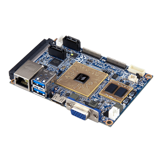
EPIA EPIA- - - - P910 EPIA EPIA P910 P910 P910 User Manual User Manual User Manual User Manual 1.3. Layout Diagram Figure Figure 1 1 1 1 : Layout diagram of : Layout diagram of the the EPIA EPIA- - - - P910 P910 mainboard mainboard (top and bottom view) (top and bottom view) - Page 13 EPIA EPIA- - - - P910 EPIA EPIA P910 P910 P910 User Manual User Manual User Manual User Manual ® CPU: VIA Eden VX11H chipset PWR1: DC-in power connector SODIMM1: DDR3 SODIMM slot J1: SPI connector BAT1: CMOS battery connector Table Table Table...
-
Page 14: Dimensions
EPIA EPIA- - - - P910 EPIA EPIA P910 P910 P910 User Manual User Manual User Manual User Manual 1.4. Dimensions Figure Figure 2 2 2 2 : Mounting holes and dimensions of the : Mounting holes and dimensions of the EPIA EPIA- - - - P910 P910 mainboard mainboard... -
Page 15: Height Distribution
EPIA EPIA- - - - P910 EPIA EPIA P910 P910 P910 User Manual User Manual User Manual User Manual 1.5. Height Distribution Figure Figure Figure Figure 3 3 3 3 : Height distribution of : Height distribution of : Height distribution of : Height distribution of the the EPIA EPIA... -
Page 16: I/O Interface I/O Interface
2. 2. 2. 2. I/O Interface I/O Interface I/O Interface I/O Interface The VIA EPIA-P910 has a wide selection of interfaces. It includes a selection of frequently used ports as part of the external I/O coastline. 2.1. External I/O Ports Figure... -
Page 17: Usb 3.0 Port
2.1.2. USB 3.0 Port The EPIA-P910 mainboard provides two USB 3.0 ports, also known as SuperSpeed USB. The USB 3.0 port has a maximum data transfer rate up to 5 Gbps and offers a backwards compatible with previous USB 2.0 specifications. -
Page 18: Vga Connector
EPIA EPIA- - - - P910 EPIA EPIA P910 P910 P910 User Manual User Manual User Manual User Manual 2.1.4. VGA Connector The 15-pin VGA connector uses a female DE-15 connector. The VGA connector is for connecting to analog displays. The pinout of the VGA connector is shown below. Figure Figure 8 8 8 8 : VGA connector diagram : VGA connector diagram... -
Page 19: Onboard Connectors
EPIA EPIA- - - - P910 EPIA EPIA P910 P910 P910 User Manual User Manual User Manual User Manual 2.2. Onboard Connectors 2.2.1. LVDS Connector The mainboard has one 24-pin LVDS panel connector on the bottom side. The onboard LVDS panel connector allows to connect the panel’s LVDS cable to support the single-channel 18-bit/24-bit display. -
Page 20: Sata Connectors
EPIA EPIA- - - - P910 EPIA EPIA P910 P910 P910 User Manual User Manual User Manual User Manual 2.2.2. SATA Connectors The two SATA connectors onboard can support up to 3 Gb/s transfer speeds. Both SATA connectors have a 7th pin1 that can provide +5V power to a SATA Disk-on-Module (DOM).
Need help?
Do you have a question about the EPIA-P910 and is the answer not in the manual?
Questions and answers