Sign In
Upload
Manuals
Brands
VIA Technologies Manuals
Motherboard
EPIA-P900
VIA Technologies EPIA-P900 Manuals
Manuals and User Guides for VIA Technologies EPIA-P900. We have
1
VIA Technologies EPIA-P900 manual available for free PDF download: User Manual
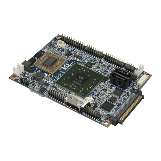
VIA Technologies EPIA-P900 User Manual (89 pages)
Pico-ITX embedded board
Brand:
VIA Technologies
| Category:
Motherboard
| Size: 3 MB
Table of Contents
Table of Contents
6
1 Product Overview
12
Key Features and Benefits
13
VIA Eden ™ X2 Processor
13
VIA VX900H Chipset
13
Expansion Option
13
Product Specifications
14
Layout Diagram
16
Figure 1: Layout Diagram of the EPIA-P900 Mainboard (Top and Bottom View)
16
Table 1: Layout Diagram Description Table of the EPIA-P900 Mainboard
17
Product Dimensions
18
Figure 2: Mounting Holes and Dimensions of the EPIA-P900
18
Height Distribution
19
Figure 3: Height Distribution of the EPIA-P900 Mainboard
19
2 I/O Interface
20
External I/O Ports
20
Figure 4: External I/O Ports
20
Table 2: Layout Diagram Description Table of External I/O Ports
20
Figure 5: HDMI Port Pinout Diagram
21
HDMI Port
21
Table 3: HDMI Port Pinout
21
Figure 6: VGA Port Pinout Diagram
22
Table 4: VGA Port Pinout
22
VGA Port
22
Figure 7: USB Port Pinout Diagram
23
Figure 8: Gigabit Ethernet Port Pinout Diagram
23
RJ45 LAN Port: Gigabit Ethernet
23
Table 5: USB 2.0 Port Pinout
23
Table 6: Gigabit Ethernet Port Pinout
23
Table 7: Gigabit Ethernet LED Color Definition
23
USB 2.0 Port
23
Onboard Connectors
24
LVDS Connector
24
Figure 9: LVDS Connector
24
Table 8: LVDS Connector Pinout
24
VGA and USB Combination Pin Header
25
Figure 10: VGA and USB Combination Pin Header
25
Table 9: VGA and USB Combination Pin Header Pinout
25
SATA Connectors
26
Figure 11: SATA Connectors
26
Table 10: SATA Connector Pinouts
26
SATA Power Connector
27
Figure 12: SATA Power Connector
27
Table 11: SATA Power Connector Pinout
27
USB and USB Device Combination Pin Header
28
Figure 13: USB and USB Device Pin Header
28
Table 12: USB and USB Device Pin Header Pinout
28
LAN Pin Header
29
Figure 14: LAN Pin Header
29
Table 13: LAN Pin Header Pinout
29
UART Connectors
30
Figure 15: UART Connectors
30
Table 14: UART Connector Pinouts
30
LPC, Smbus, and GPIO Combination Pin Header
31
Figure 16: LPC, Smbus and GPIO Combination Pin Header
31
Table 15: LPC, Smbus and GPIO Combination Pin Header Pinout
31
SPI Flash Connector
32
Figure 17: SPI Connector
32
Table 16: SPI Connector Pinout
32
CMOS Battery Connector
33
Figure 18: CMOS Battery Connector
33
Table 17: CMOS Battery Connector Pinout
33
Front Panel and PS2 Combination Pin Header
34
Figure 19: Front Panel and PS2 Combination Pin Header
34
Table 18: Front Panel and Combination Pin Header Pinout
34
Front Audio Pin Header
35
Figure 20: Front Audio Pin Header
35
Table 19: Front Audio Pin Header Pinout
35
CPU Fan Connector
36
Figure 21: CPU Fan Connector
36
Table 20: CPU Fan Connector Pinout
36
DC-In Power Connector
37
Figure 22: DC-In Power Connector
37
Table 21: DC-In Power Connector Pinout
37
3 Jumpers
38
Clear CMOS Jumper
38
Figure 23: CLEAR CMOS Jumper
38
Table 22: CLEAR CMOS Jumper Settings
38
Panel Power Select Jumper
39
Figure 24: LVDS Panel Power Select Jumper
39
Table 23: LVDS Panel Power Select Jumper Settings
39
Backlight Power Select Jumper
40
Figure 25: Backlight Power Select Jumper
40
Table 24: Backlight Power Select Jumper Settings
40
4 Expansion Slots
42
Pcie and USB Combination Connector
42
Figure 26: Pcie and USB Combination Connector
42
Table 25: Pcie and USB Combination Connector Pinout
43
DDR3 SODIMM Memory Slot
44
Figure 27: DDR3 SODIMM Memory Slot
44
Figure 28: Inserting the Memory Module
45
Figure 29: Locking the Memory Module
45
Installing a Memory Module
45
Figure 30: Installing Memory Thermal Pad
46
Figure 31: Disengaging the SODIMM Locking Clips
47
Figure 32: Removing the Memory Module
47
Removing a Memory Module
47
5 Hardware Installation
48
Removing and Installing the P830-A Companion Card
48
Removing the P830-A
48
Figure 33: Unscrewing the P830-A Companion Card
48
Figure 34: Pulling the P830-A Companion Card
49
Installing the P830-A
50
Figure 35: Aligning the P830-A Companion Card
50
Figure 36: Connecting P830-A Companion Card
51
Figure 37: Securing the P830-A Companion Card
51
Installing the P830-B Expansion Card
52
Figure 38: Installing the P830-B Expansion Card
52
Installing into a Chassis
53
Suggested Minimum Chassis Dimensions
53
Figure 39: Suggested Minimum Chassis Dimensions
53
Suggested Minimum Chassis Height
54
Figure 40: Suggested Minimum Internal Chassis Ceiling Height
54
Suggested Keepout Areas
55
Figure 41: Suggested Keepout Areas
55
6 BIOS Setup Utility
56
Entering the BIOS Setup Utility
56
Control Keys
56
Getting Help
56
System Overview
57
Amibios
57
Processor
57
System Memory
57
System Time
57
Figure 42: Illustration of the Main Menu Screen
57
System Date
58
Advanced Settings
59
Figure 43: Illustration of the Advanced Settings Screen
59
CPU Configuration
60
Figure 44: Illustration of the CPU Configuration Screen
60
Figure 45: Illustration of SATA Configuration Screen
61
Figure 46: Illustration of SATA-1 Primary IDE Screen
61
SATA Configuration
61
Figure 47: Illustration of Superio Configuration Screen
63
Superio Configuration
63
Table 26: Serial Port Addresses and Irqs
63
Figure 48: Illustration of Hardware Health Configuration Screen
64
Hardware Health Configuration
64
ACPI Configuration
65
Figure 49: Illustration of ACPI Configuration Screen
65
APM Configuration
66
Figure 50: Illustration of APM Configuration Screen
66
Event Log Configuration
70
Figure 51: Illustration of Event Log Configuration Screen
70
Figure 52: Illustration of Spread Spectrum Configuration Screen
71
Spread Spectrum Configuration
71
Figure 53: Illustration of USB Configuration Screen
72
USB Configuration
72
CRB Configuration
73
Figure 54: Illustration of CRB Configuration Screen
73
Table 27: Panel Types Resolution
74
Boot Settings
76
Boot Settings Configuration
76
Figure 55: Illustration of Boot Settings Screen
76
Figure 56: Illustration of Boot Settings Configuration
76
Boot Device Priority
78
Figure 57: Illustration of Boot Device Priority
78
Security Settings
79
Change Supervisor Password
79
Change User Password
79
Clear User Password
79
Figure 58: Illustration of Security Settings Screen
79
Password Check
80
Exit Options
81
Save Changes and Exit
81
Discard Changes and Exit
81
Discard Changes
81
Load Optimal Defaults
81
Figure 59: Illustration of Exit Options Screen
81
7 Driver Installation
82
Microsoft Driver Support
82
Linux Driver Support
82
Appendix A. Power Consumption Report
84
Epia-P900-10
84
Burn-In 3Dmark06, 1280 X 1024 (Demo Mode)
84
Passmark Burn-In (CPU Usage = 100%)
84
Power DVD 10 to Player H.264 1080I_10M Movie
85
Power DVD 10 to Player MPEG2 1080P_40M Movie
85
Idle at Windows 7 X64
85
Suspend S1
85
Suspend S3
85
Suspend S4
86
Suspend S5
86
Appendix B. Pin Header and Connector Vendor Lists
88
EPIA-P900 Mainboard
88
Table 28: EPIA-P900 Pin Header and Connector Vendor Lists
88
Advertisement
Advertisement
Related Products
VIA Technologies EPIA-P910
VIA Technologies EPIA-PX10000G - VIA Motherboard - Pico ITX
VIA Technologies EPIA-PE
VIA Technologies EPIA-P830
VIA Technologies EPIA-PX
VIA Technologies EPIA-PN
VIA Technologies EPIA-P700
VIA Technologies EPIA-P710
VIA Technologies EPIA-PD Mini-ITX
VIA Technologies EPIA-P820
VIA Technologies Categories
Motherboard
Computer Hardware
Desktop
Control Unit
Industrial PC
More VIA Technologies Manuals
Login
Sign In
OR
Sign in with Facebook
Sign in with Google
Upload manual
Upload from disk
Upload from URL