Sign In
Upload
Manuals
Brands
Vertiv Manuals
Power Supply
NetSure 7100 Series
Vertiv NetSure 7100 Series Manuals
Manuals and User Guides for Vertiv NetSure 7100 Series. We have
13
Vertiv NetSure 7100 Series manuals available for free PDF download: Installation Manual, Quick Start Manual, User Manual, Installation And User Manual, Test Instructions
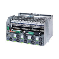
Vertiv NetSure 7100 Series Installation Manual (222 pages)
-48V DC Power System
Brand:
Vertiv
| Category:
Power Supply
| Size: 32 MB
Table of Contents
Table of Contents
3
Admonishments Used in this Document
6
Important Safety Instructions
7
Safety Admonishments Definitions
7
General Safety
7
Voltages
7
AC Input Voltages
7
DC Input Voltages
7
DC Output and Battery Voltages
8
Battery
8
Personal Protective Equipment (PPE)
9
Hazardous Voltage
9
Handling Equipment Containing Static Sensitive Components
10
Maintenance and Replacement Procedures
10
Static Warning
11
Customer Documentation Package
13
Installation Acceptance Checklist
14
Installing the System
16
General Requirements
16
Procedures When the System Is Installed in an Enclosure
17
Removing the Enclosure Rear Panels
17
Removing the Enclosure Side Panels
17
AC Input Conduit Options
17
Reversing the Enclosure Front Door
18
Placing and Securing the Relay Rack(S) to the Floor (if Applicable)
20
Placing the Enclosures, Bolting Enclosures Together, and Securing the Enclosure(S) to the Floor (if Applicable)
24
Mounting the Distribution Cabinet with Module Mounting
30
Assembly(S)
30
Installing a 582127000 List 93 Battery Tray
34
Only)
34
Installing a Battery Tray
34
Installing Optional Battery Disconnect Circuit Breakers
35
Installing Optional Anderson Battery Connector Kit
36
Installing Optional Front Battery Cover
37
Installing Optional Circuit Breaker Guard
38
Installing a Battery Tray Mounting Kit, P/N 565004
39
Installation Only)
39
Removing the Enclosure Rear and Side Panels
39
Installing the List 93 Battery Tray
43
Installing the Enclosure Rear and Side Panels
43
Installing Optional Battery Busbar Extension Kit, Part No. 562364
44
Installing Optional Battery Busbar Extension Kit, Part No. 554541
46
Installing Optional Lug Adapter Busbar Kits, Part Nos. 534449 and
48
Installing Optional Lug Adapter Busbar Kit, Part No. 562888
50
Installing Circuit Breakers and Fuses
52
Setting Jumpers and Switch Options
66
Circuit Card Locations
66
Jumpers on System Interface Circuit Card (Main Bay Only)
68
Switch Settings on IB2 Interface Board (Main Bay Only)
69
Switch Setting on Optional EIB Interface Board (Main Bay Only)
70
Switch Setting on SM-DU (Supplemental Bays Only)
73
Switch Setting on SM-DU
77
Making Electrical Connections
79
Important Safety Instructions
79
Wiring Considerations
79
Relay Rack or Enclosure Grounding Connection (Frame Ground)
80
Central Office Ground Connection
80
Nominal 208 VAC, 240 VAC, 277 VAC, or 277 VAC / 480 VAC Input and Equipment Grounding Connections (if Equipped)
82
Volts DC Input and Equipment Grounding Connections
114
Equipped)
114
External Alarm, Reference, Monitoring, and Control Connections
123
Circuit Card Locations
123
System Interface Circuit Card
125
IB2 (Controller Interface Board) Connections (if Required)
127
Only)
127
Optional EIB (Controller Extended Interface Board) Connections
132
Required) (Main Bay Only)
132
Optional SM-DU+ and Shunt Interface Board
138
Connecting a Device or System to the Controller's CAN Bus
140
Controller Ethernet Connection (if Required)
141
Bay-To-Bay Communications Cable Connections
145
Installing Bay-To-Bay Busbars (582127000 List 1 with List 2 / List 3) (for System Mounted in a Relay Rack)
148
Installing Bay-To-Bay Busbars (582127000 List 1 with List 7 / List 8) (for System Mounted in an Enclosure)
150
Control Bus Connections between Controller and Module Mounting Assemblies Spec. No. 588705000 and 588705500
153
Control Bus Connections between Controller and Module Mounting Assemblies Spec. No. 588705300
155
Control Bus Connections between Controller and Module Mounting Assemblies Spec. No. 588705400
157
Connecting Converter Output Cables 582127000 List 60
159
Load Connections
162
Recommended Torques
162
Load Connections to Single Voltage Distribution Panels
163
Load Connections to Dual Voltage Distribution Panels
168
Load Connections to Return Bar
173
Load Connections to Bulk Output Panel
173
Load Connections to GMT Distribution Fuse Block
174
Battery Connections
175
Important Safety Instructions
175
Recommended Torques
175
Battery Connections to Optional Battery Disconnect Distribution
175
Panels
175
Battery Connections to Distribution Cabinet Battery Busbars (for System Mounted in a Relay Rack or Enclosure)
179
Battery Connections to Bay-To-Bay Rectifier Busbars (582127000 List 1 with List 2 / List 3) (for System Mounted in a Relay Rack)
182
Battery Connections to Optional Battery Busbar Extension Kit P/N 562364 (for System Mounted in a Relay Rack or Enclosure)
183
Battery Connections to Optional Battery Busbar Extension Kit P/N 554541 (for System Mounted in an Enclosure)
185
Battery Connections to Optional Battery Landing Busbar Kit P/N 553584 (for System Mounted in a Relay Rack)
186
Battery Connections to Optional Battery Landing Busbar Kit P/N 555478 (for System Mounted in a Relay Rack)
187
Installing and Connecting Batteries in List 93 Battery Tray (if Furnished) (for System Mounted in a Relay Rack)
188
Installing the Modules
197
Installing Rectifier or Converter Modules into Spec. No. 588705000 Module Mounting Assemblies
197
Installing Rectifier Modules into Spec. No. 588705500 Module
199
Mounting Assemblies
201
Installing the Rectifier and Converter Modules into Spec. no
201
588705300 Module Mounting Assemblies
201
Installing Rectifier Modules into Spec. No. 588705400 Module
203
Mounting Assemblies
203
Initially Starting, Configuring, and Checking System Operation
205
Initial Startup Preparation
205
Initially Starting the System
205
ACU+ Controller Procedure
205
NCU Controller Procedure
213
Checking System Status
219
Final Steps
220
Advertisement
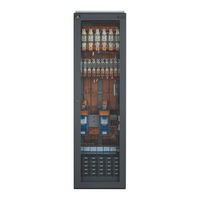
Vertiv NetSure 7100 Series Quick Start Manual (130 pages)
48V DC Power System
Brand:
Vertiv
| Category:
Power Supply
| Size: 16 MB
Table of Contents
Table of Contents
3
Admonishments Used in this Document
5
Important Safety Instructions
6
General Safety
6
Voltages
6
AC Input Voltages
6
DC Input Voltages
6
DC Output and Battery Voltages
7
Battery
7
Personal Protective Equipment (PPE)
8
Hazardous Voltage
8
Handling Equipment Containing Static Sensitive Components
9
Maintenance and Replacement Procedures
9
Static Warning
10
Customer Documentation Package
11
Physical Installation
13
Installing Circuit Breakers and Fuses
13
Make Jumper and Switch Settings
21
Electrical Connections
22
Important Safety Instructions
22
Make Nominal 208 VAC, 240 VAC, 277 VAC, or 277 VAC / 480 VAC Input and Equipment Grounding Connections (if Equipped)
22
Connections (if Equipped)
50
Connections
56
Circuit Card Locations
56
System Interface Circuit Card
57
Only)
59
Optional EIB (Controller Extended Interface Board) Connections
64
Required) (Main Bay Only)
64
Optional SM-DU+ and Shunt Interface Board
70
Connecting a Device or System to the Controller's CAN Bus
72
Make Controller Ethernet Connection (if Required)
73
Make Bay-To-Bay Communications Cable Connections
76
Installing Bay-To-Bay Busbars (582127000 List 1 with List 2 / List 3) (for System Mounted in a Relay Rack)
76
Installing Bay-To-Bay Busbars (582127000 List 1 with List 7 / List 8) (for System Mounted in an Enclosure)
76
Connecting Converter Output Cables 582127000 List 60
83
Make Load Connections
86
Recommended Torques
86
Load Connections to Single Voltage Distribution Panels
87
Load Connections to Dual Voltage Distribution Panels
92
Load Connections to Return Bar
97
Load Connections to Bulk Output Panel
97
Load Connections to GMT Distribution Fuse Block
98
Make Battery Connections
99
Recommended Torques
99
Panels
99
Battery Connections to Distribution Cabinet Battery Busbars (for System Mounted in a Relay Rack or Enclosure)
103
Battery Connections to Bay-To-Bay Rectifier Busbars (582127000 List 1 with List 2 / List 3) (for System Mounted in a Relay Rack)
105
List 93 Battery Tray
106
Installing the Modules
106
Installing Rectifier or Converter Modules into Spec. No. 588705000 Module Mounting Assemblies
106
Installing Rectifier Modules into Spec. No. 588705500 Module
108
Mounting Assemblies
110
Installing the Rectifier and Converter Modules into Spec. no
110
588705300 Module Mounting Assemblies
110
Installing Rectifier Modules into Spec. No. 588705400 Module
112
Mounting Assemblies
112
Initially Starting, Configuring, and Checking System Operation
114
Initial Startup Preparation
114
Initially Starting the System
114
ACU+ Controller Procedure
114
NCU Controller Procedure
122
Checking System Status
127
Final Steps
128
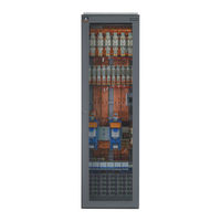
Vertiv NetSure 7100 Series Installation And User Manual (56 pages)
Hybrid DC Power System
Brand:
Vertiv
| Category:
Power Supply
| Size: 9 MB
Table of Contents
Table of Contents
3
Admonishments Used in this Document
6
Important Safety Instructions
7
Safety Admonishments Definitions
7
General Safety
7
Voltages
7
Hazardous Voltage
7
DC Voltage (Solar)
7
DC Voltage (Independent DC Input)
7
AC Input Voltages
8
DC Output
8
Battery
8
Personal Protective Equipment (PPE)
8
Handling Equipment Containing Static Sensitive Components
8
Maintenance and Replacement Procedures
8
Static Warning
9
1 General Information and Installation Acceptance Checklist
11
Customer Documentation Package
11
System Description
11
19" Multi-Function Subrack
11
23" Multi-Function Subrack
12
Battery Distribution
12
Load Distribution
12
Rectifier
12
Solar Converter
12
Independent DC Port
12
58 VDC
12
500 A
12
NCU Controller
13
CAN-Bus Extension
13
RS232, RS485 and Fuel Sensor Connector
13
IB2, IB4, EIB and SPD Board
13
Load Disconnect, Including the Optional Three-Stage Priority
13
Installation Acceptance Checklist
13
19" Subracks
15
23" Subracks
17
2 Physically Installing the Power System
18
General Requirements
18
Cabinets
18
Mounting a Netsure™ Standalone Cabinet (if Provided)
19
Installing Optional Foot Kit (if Required)
19
Anchoring to the Floor
20
Anchoring to the Wall
21
Mounting a Standalone Subrack in a Customer-Provided Cabinet
22
Mounting a Standalone Subrack on a Battery Rack
23
Installing the Battery Rack
23
Installing the Subrack on the Battery Rack
23
Installing Batteries in a Battery Rack
24
Installing Load Distribution or Battery Disconnect Circuit Breakers
24
3 Setting Switch Options
25
Circuit Board Locations
25
Switch Settings on IB2 Interface Board
25
Switch Settings on EIB Interface Board
26
4 Making Electrical Connections
27
Important Safety Instructions
27
Wiring Considerations
27
Cable Routing Guidelines
27
Subrack in Netsure™ Cabinet
27
Standalone Subrack
27
Earthing Connections
28
DC Solar and AC Mains Connections
30
DC Solar Input
30
AC Input
30
AC Terminal Connection
30
Load Connections
33
Wires Guidelines
33
Load Configuration (LVD1/LVD2/LVD3)
33
Independent DC Power Port Connections
35
Battery Connections
35
Important Safety Instructions
35
External Alarm, Reference, Monitoring and Control Connections
36
Connection Locations
36
Connections Directly to the NCU Control Unit
36
Connections to the Optional Connection Kit, BMY1100069/1
37
Connection of 1-2 Fuel Level Sensors
38
Optional IB4 Board Connections
38
Optional IB2 Interface Board Connections
38
Optional EIB Interface Board Connections
39
Temperature Sensors Connections
42
Ethernet Connection to the NCU (if Required)
42
5 Initially Starting and Checking the System
44
6 Operating Procedures
44
Controllers and Rectifiers
44
Independent DC Power Port
44
Local Controls and Indicators
44
Batteries
44
7 Maintenance
45
System Maintenance Procedures
45
Adding a Rectifier/Converter Module to the System
45
Adding a Load Distribution or Battery Disconnect Circuit Breaker
45
8 Troubleshooting and Repair
47
Controllers and Rectifiers
47
NCU Controller Configuration
47
System Troubleshooting Information
47
Troubleshooting Alarm Conditions on the NCU Controller
47
Checking the NCU Current Limit Point after Adding or Removing a Rectifier/Converter
47
Clearing a Rectifier/Converter Communications Fail Alarm after Removing a Rectifier/Converter
47
Clearing a Rectifier/Converter Lost Alarm
47
Replacement Information
48
Replacement Assemblies
48
Replacement Procedures
48
Replacing a Rectifier Module
48
Replacing a Solar Converter Module
48
Replacing the NCU Controller
48
Replacing Load Distribution or Battery Disconnect Circuit Breakers
48
Replacing the Load Circuit Breaker Alarm Board
50
Replacing the Optional DC SPD Board
50
Circuit Board Replacement Procedures
52
IB2 Board and Optional EIB Board Replacement
52
Replacing the IB4 Board (Optional)
54
Advertisement
Vertiv NetSure 7100 Series User Manual (106 pages)
-48 VDC Power System
Brand:
Vertiv
| Category:
Power Supply
| Size: 16 MB
Table of Contents
Table of Contents
3
Admonishments Used in this Document
5
Important Safety Instructions
6
Static Warning
9
Customer Documentation Package
11
System Description
12
Operating Procedures
14
Controller, Rectifiers, and Converters
14
ESTOP Function
14
Controller Battery Charge Current Limit Feature
14
Local Controls and Indicators
15
Procedures When the System Is Installed in an Enclosure
23
Removing the Enclosure Rear Panels
23
Removing the Enclosure Side Panels
23
AC Input Conduit Options
23
Maintenance
25
System Maintenance Procedures
25
Adding a Rectifier Module to an Existing Spec. No. 588705000, 588705400, or 588705500 Module Mounting
25
Assembly
25
Adding a Rectifier or Converter Module to an Existing Spec. No. 588705300 Module Mounting Assembly
26
Installing a Field Expansion Module Mounting Assembly Spec. No. 588705000 or 588705500 in a System Installed in a Relay Rack or an Enclosure
29
Installing a Field Expansion Module Mounting Assembly Spec. No. 588705400 in a System Installed in a Relay Rack or an Enclosure
37
Reconfiguring a Dual Voltage Distribution Panel (List DE, DF, DG, DH, DJ, DK, FE, FF, FG, FH, FJ, FK)
42
Changing the Controller's LVD Control Level for a Contactor
51
Adding a Supplemental Bay in the Field
51
Installing Optional Second IB2 (Controller Interface Board) or Optional Second EIB
53
Interface Board)
53
Troubleshooting and Repair
54
Contact Information
54
Controller, Rectifiers, and Converters
54
Controller Configuration
54
System Troubleshooting Information
54
Replacement Information
55
Replacement Procedures
56
Replacing a Rectifier Module (in a Spec. No. 588705000 Module Mounting Assembly)
56
Replacing a Rectifier or Converter Module (in a Spec. No. 588705300 Module Mounting Assembly)
56
Replacing a Rectifier Module (in a Spec. No. 588705400 Module Mounting Assembly)
56
Replacing a Rectifier Module (in a Spec. No. 588705500 Module Mounting Assembly)
56
Replacing the Controller
56
Replacing a Distribution Device
56
Replacing a Distribution Panel (List AA, AB, AC, AD, AE, AF, AG, AH, AJ, AK, BA, BB, BC, BD, BF, and BH)
66
Replacing a Distribution Panel (List AL, AN, DE, DF, DG, DH, DJ, DK, FE, FF, FG, FH, FJ, FK)
69
Replacing a Distribution Panel List AA, AB, AC, AD, AE, AF, AG, AH, AJ, AK, DA, DB, DC, DD, BA, BB
72
BC, BD, BE, BF, BG, or BH with a List AL, AN, DE, DF, DG, DH, DJ, or DK, FE, FF, FG, FH, FK
72
Replacing a Distribution Panel
77
BC, BD, BE, BF, BG, or BH with am or AP)
77
Replacing a Distribution Panel (List AA, AB, AC, AD, AE, AF, AG, AH, AJ, AK, DA, DB, DC, DD, BA, BB, BC, BD, BE, BF, BG, or BH with EA)
80
Circuit Card Replacement Procedures
83
Replacing a Battery or Load Disconnect Contactor
100
Vertiv NetSure 7100 Series Installation Manual (74 pages)
48V DC Power System
Brand:
Vertiv
| Category:
Power Supply
| Size: 5 MB
Table of Contents
Table of Contents
3
Admonishments Used in this Document
5
Important Safety Instructions
6
General Safety
6
Voltages
6
AC Input Voltages
6
DC Output and Battery Voltages
6
Battery
7
Personal Protective Equipment (PPE)
8
Hazardous Voltage
8
Handling Equipment Containing Static Sensitive Components
8
Maintenance and Replacement Procedures
8
Static Warning
9
Customer Documentation Package
11
Installation Acceptance Checklist
12
Installing the System
13
General Requirements
13
Securing the Relay Rack to the Floor
14
Installing Battery Trays
15
Installing Optional Lug Adapter Busbar Kits, Part Nos. 534449 and
22
Installing Circuit Breakers and Fuses
24
Setting Jumpers and Switch Options
28
Circuit Card Locations
28
Jumper on System Interface Board
29
Switch Setting on IB2 Controller Interface Board
30
Switch Setting on Optional EIB Controller Extended Interface Board
30
Making Electrical Connections
32
Important Safety Instructions
32
Wiring Considerations
32
Relay Rack Grounding Connection (Frame Ground)
33
Central Office Ground Connection
33
Nominal 208 VAC / 240 VAC Input and Equipment Grounding
34
Connections
34
External Alarm, Reference, Monitoring, and Control Connections
37
Circuit Card Locations
37
Temperature Probes
37
System Interface Board
38
IB2 (Controller Interface Board) Connections (if Required)
40
Required)
45
Optional EIB (Controller Extended Interface Board) Connections
48
Connecting a Device or System to the NCU CAN Bus (if Required)
51
NCU Controller Ethernet Connection (if Required)
52
Load Connections
53
Recommended Torques
53
Load Connections to Single Voltage Distribution Panels
53
Load Connections to Dual Voltage Distribution Panels
53
Load Connections to GMT Distribution Fuse Block
54
External Battery Connections
55
Important Safety Instructions
55
Recommended Torques
55
Battery Connections to Distribution Cabinet Battery Busbars
55
Installing and Connecting Batteries in the Battery Trays
58
Furnished)
60
Special Application Rectifier Bus Landing Point Kit P/N 563686
61
Generator Input Breaker Kit (P/N 564219)
62
Installing the Rectifier and Converter Modules
63
Initially Starting, Configuring, and Checking System Operation
65
Initial Startup Preparation
65
Initially Starting the System
65
NCU Controller Initialization
65
Checking System Status
71
Final Steps
72
Vertiv NetSure 7100 Series Installation Manual (70 pages)
-48 VDC Power System
Brand:
Vertiv
| Category:
Power Supply
| Size: 6 MB
Table of Contents
Table of Contents
3
Admonishments Used in this Document
5
Important Safety Instructions
6
Safety Admonishments Definitions
6
Safety and Regulatory Statements
6
Déclarations de Sécurité et de Réglementation
6
Customer Documentation Package
7
Installation Acceptance Checklist
7
Installing the System
8
General Requirements
8
Securing the Relay Rack to the Floor
9
Installing Battery Trays
10
Installing Optional Lug Adapter Busbar Kits, Part Nos. 534449 and 514714
17
Installing Circuit Breakers and Fuses
19
Setting Jumpers and Switch Options
23
Circuit Card Locations
23
Jumper on System Interface Board
24
Switch Setting on IB2 Controller Interface Board
25
Switch Setting on Optional EIB Controller Extended Interface Board
25
Making Electrical Connections
27
Important Safety Instructions
27
Wiring Considerations
27
Relay Rack Grounding Connection (Frame Ground)
28
Central Office Ground Connection
28
SPD (Surge Protection Device) (if Equipped) Earth Ground Connection
29
Nominal 208 VAC / 240 VAC Input and Equipment Grounding Connections
30
External Alarm, Reference, Monitoring, and Control Connections
33
Circuit Card Locations
33
Temperature Probes
33
System Interface Board
34
IB2 (Controller Interface Board) Connections (if Required)
35
Optional EIB (Controller Extended Interface Board) Connections (if Required)
40
Connecting a Device or System to the NCU CAN Bus (if Required)
46
NCU Controller Ethernet Connection (if Required)
47
Load Connections
48
Recommended Torques
48
Load Connections to Single Voltage Distribution Panels
48
Load Connections to Dual Voltage Distribution Panels
48
Load Connections to GMT Distribution Fuse Block
50
External Battery Connections
51
Important Safety Instructions
51
Recommended Torques
51
Battery Connections to Distribution Cabinet Battery Busbars
51
Installing and Connecting Batteries in the Battery Trays (if Furnished)
54
Special Application Rectifier Bus Landing Point Kit P/N 563686
57
Generator Input Breaker Kit (P/N 564219)
58
Installing the Rectifier and Converter Modules
59
Initially Starting, Configuring, and Checking System Operation
61
Initial Startup Preparation
61
Initially Starting the System
61
NCU Controller Initialization
61
Checking System Status
67
Final Steps
67
Vertiv NetSure 7100 Series Installation Manual (52 pages)
-48 VDC Power System
Brand:
Vertiv
| Category:
Power Supply
| Size: 9 MB
Table of Contents
Table of Contents
3
Admonishments Used in this Document
4
Important Safety Instructions
5
Static Warning
8
Customer Documentation Package
9
Installation Acceptance Checklist
9
Installing the System
10
General Requirements
10
Mounting the System in an Equipment Rack
11
Installing Optional Lug Adapter Busbar Kits
12
Installing Optional EIB (Controller Extended Interface Board)
13
Installing Circuit Breakers and Fuses
15
Setting Jumper and Switch Options
18
Location of Circuit Cards with Jumper and Switch Options
18
Jumper Settings on the System Interface Circuit Card
19
Switch Settings on the IB2 (Controller Interface Board)
20
Switch Settings on Optional EIB (Controller Extended Interface Board)
21
Making Electrical Connections
22
Important Safety Instructions
22
Wiring Considerations
22
Power System Frame Grounding Connection
23
Central Office Ground Connection
23
AC Input and Equipment Grounding Connections (Nominal 208 VAC, 240 VAC, 277 VAC, Single Phase)
23
External Alarm, Reference, Monitoring, and Control Connections
26
Location of Circuit Cards with External Alarm, Reference, Monitoring, and Control Connectors
26
System Interface Circuit Card Connections (if Required)
27
IB2 (Controller Interface Board) Connections (if Required)
29
Optional EIB (Controller Extended Interface Board) Connections (if Required)
34
NCU Controller Ethernet Connection (if Required)
39
Load Connections
41
Load Connections to Distribution Panels and Load Return Busbars
41
Load Connections to an Optional Bullet Nose 6-Position GMT Distribution Fuse Block, P/N 549017
42
Battery Connections
43
Installing Rectifier Modules
44
Initially Starting, Configuring, and Checking System Operation
45
Important Safety Instructions
45
Initial Startup Preparation
45
Initially Starting the System
45
NCU Controller Initialization
45
Verifying and Setting the NCU Controller as Required for Your Application
47
Checking System Status
50
Final Steps
50
Vertiv NetSure 7100 Series User Manual (48 pages)
-48 VDC Power System
Brand:
Vertiv
| Category:
Power Supply
| Size: 8 MB
Table of Contents
Table of Contents
3
Admonishments Used in this Document
4
Important Safety Instructions
5
Safety Admonishments Definitions
5
Safety and Regulatory Statements
5
Déclarations de Sécurité et de Réglementation
5
Customer Documentation Package
7
System Description
7
Lists 100, 101, 102, 103, and 203
7
Lists 500, 501, 502, and 503
8
Operating Procedures
9
Controller, Rectifiers, and Converters
9
ESTOP Function
10
Controller Battery Charge Current Limit Feature
10
Local Controls and Indicators
10
Controller, Rectifiers, and Converters
10
Distribution Cabinet
10
Maintenance
13
System Maintenance Procedures
13
Adding a Rectifier or Converter Module to an Existing Module Mounting Assembly Spec. No. 588705300
13
Installing a Field Expansion Module Mounting Assembly Spec. No. 588705300
16
Reconfiguring a Dual Voltage Distribution Panel (List DJ, FG, and FK)
21
Removing the Distribution Panel
21
Reworking the Distribution Panel
23
Replacing the Distribution Panel
29
Troubleshooting and Repair
30
Contact Information
30
Controller, Rectifiers, and Converters
30
Controller Configuration
30
System Troubleshooting Information
30
Replacement Information
31
Replacement Procedures
31
Replacing a Rectifier or Converter Module
31
Replacing the NCU Controller
31
Replacing a Distribution Device
32
Replacing a Distribution Panel (List AL, DJ, FG, and FK)
34
Circuit Card Replacement Procedures
35
Replacing a Battery Disconnect Contactor
40
Replacing an SPD (Surge Protection Device) (if Furnished)
42
Vertiv NetSure 7100 Series User Manual (44 pages)
Brand:
Vertiv
| Category:
Power Supply
| Size: 4 MB
Table of Contents
Table of Contents
3
Admonishments Used in this Document
5
Important Safety Instructions
6
General Safety
6
Voltages
6
AC Input Voltages
6
DC Output and Battery Voltages
6
Battery
7
Personal Protective Equipment (PPE)
8
Hazardous Voltage
8
Handling Equipment Containing Static Sensitive Components
8
Maintenance and Replacement Procedures
8
Static Warning
9
Customer Documentation Package
10
System Description
11
Operating Procedures
13
Controller, Rectifiers, and Converters
13
ESTOP Function
13
Controller Battery Charge Current Limit Feature
13
Local Controls and Indicators
14
Controller, Rectifiers, and Converters
14
Distribution Cabinet
14
Maintenance
17
System Maintenance Procedures
17
Adding a Rectifier or Converter Module to an Existing Module Mounting Assembly Spec. No. 588705300
17
Reconfiguring a Dual Voltage Distribution Panel (List DJ)
20
Removing the Distribution Panel
20
Reworking the Distribution Panel
22
Replacing the Distribution Panel
28
Troubleshooting and Repair
29
Contact Information
29
Controller, Rectifiers, and Converters
29
Controller Configuration
29
System Troubleshooting Information
29
Replacement Information
30
Replacement Procedures
30
Replacing a Rectifier or Converter Module
31
Replacing the NCU Controller
31
Replacing a Distribution Device
31
Replacing a Distribution Panel (List AL, DJ)
34
Circuit Card Replacement Procedures
35
Vertiv NetSure 7100 Series Installation And User Manual (32 pages)
Site Monitoring Unit
Brand:
Vertiv
| Category:
Measuring Instruments
| Size: 0 MB
Table of Contents
Table of Contents
3
Admonishments Used in this Document
5
Important Safety Instructions
6
Safety Admonishments Definitions
6
General Safety
6
Handling Equipment Containing Static Sensitive Components
6
Static Warning
7
Introduction
9
Overview
9
Specifications
10
General Technical Specifications
10
Dimensions
10
Weight
10
Switch and Jumper Settings
11
General
11
Switch Settings on SM-DUE
11
Jumper Settings on SM-DUE
12
Installation
14
General Requirements
14
Installation Methods
14
Electrical Connections
16
Important Safety Instructions
16
General
16
Wiring Considerations
16
SM-IO2 Frame Ground Connection
16
Customer Connections to SM-DUE
16
Input Power Voltage Connection
19
VDC Power Supply Output Connection
20
Ten (10) Monitoring Input Blocks Connections
21
CAN Bus Port Connection
25
Initially Starting, Configuring, and Checking SM-IO2 Operation
27
Initial Startup Preparation
27
Initially Starting the SM-IO2
27
Configuring the SM-IO2
27
Operation
28
SM-DUE Indicators
28
Programming
28
Troubleshooting and Repair
29
Important Safety Instructions
29
Contact Information
29
Troubleshooting
29
Vertiv NetSure 7100 Series User Manual (34 pages)
48 VDC Power System
Brand:
Vertiv
| Category:
Power Supply
| Size: 5 MB
Table of Contents
Table of Contents
3
Admonishments Used in this Document
4
Important Safety Instructions
5
Static Warning
8
Customer Documentation Package
9
System Description
10
Operating Procedures
11
Controller and Rectifiers
11
ESTOP Function
11
Controller Battery Charge Current Limit Feature
11
Local Controls and Indicators
11
System Alarm Indicator
12
Circuit Cards
12
Maintenance
16
Important Safety Instructions
16
System Maintenance Procedures
16
Adding a Rectifier Module to an Empty Module Mounting Position
16
Installing Optional EIB (Controller Extended Interface Board)
16
Troubleshooting and Repair
17
Important Safety Instructions
17
Contact Information
17
Controller and Rectifiers
17
Controller Configuration
17
System Troubleshooting Information
17
Replacement Information
18
Replacement Procedures
18
Replacing a Rectifier Module
18
Replacing the NCU Controller
18
Replacing a Distribution Device
18
Circuit Card Replacement Procedures
21
Replacing the Distribution Panel
28
Replacing a Battery Disconnect Contactor (if Furnished)
30
Vertiv NetSure 7100 Series Test Instructions (16 pages)
DC Power System with NCU – Hybrid
Brand:
Vertiv
| Category:
Power Supply
| Size: 2 MB
Table of Contents
Table of Contents
3
Admonishments Used in this Document
4
Important Safety Instructions
5
Safety Admonishments Definitions
5
General Safety
5
Voltages
5
Hazardous Voltage
5
AC Input Voltages
5
DC Output
6
Battery
6
Personal Protective Equipment (PPE)
6
Handling Equipment Containing Static Sensitive Components
6
Maintenance and Replacement Procedures
6
Static Warning
7
1 Introduction
9
Abbreviations Used in this Document
9
General
9
2 Preliminaries
9
Documents
9
Test Equipment
9
Safety Rules
9
3 Installation Check
10
Procedure
10
4 Start-Up Preparations
11
Procedure
11
5 Start-Up and Installation Test
11
6 Test of Signals and Supervision
12
Procedure for Rectifiers/S48-4300E3, E4 Converters
12
Independent DC Port (if Applicable)
13
7 Final Steps
13
Procedure
13
Vertiv NetSure 7100 Series Installation And User Manual (22 pages)
Supervision Module for Distribution Unit Plus
Brand:
Vertiv
| Category:
Control Unit
| Size: 3 MB
Table of Contents
Table of Contents
3
Admonishments Used in this Document
4
Important Safety Instructions
5
Static Warning
6
1 Introduction
7
Overview
7
Technical Specifications
7
2 Switch Settings
9
General
9
3 Installation
12
Mounting
12
4 Electrical Connections
12
Important Safety Instructions
12
Wiring Considerations
12
General
12
Input Fusing
12
Frame Grounding Connection
13
Load Shunt Input Connections
14
Fuse Alarm (FA) Input Connections
14
Input Power Connections
16
NCU CAN Bus Connections
17
5 Operation
19
Indicators
19
Configuring the NCU SM-DU+ Parameters
20
Advertisement
Related Products
Vertiv NetSure 710 Series
Vertiv NetSure 710NPBA
Vertiv NetSure 722NBBB
Vertiv NetSure 7200
Vertiv NetSure 700NVBA
Vertiv NetSure 731 A91
Vertiv NetSure 731 A91-S1
Vertiv NetSure 731 A91-S2
Vertiv NetSure 731 A91-S3
Vertiv NetSure 731 C62 Series
Vertiv Categories
UPS
Power Supply
Switch
Power distribution unit
Air Conditioner
More Vertiv Manuals
Login
Sign In
OR
Sign in with Facebook
Sign in with Google
Upload manual
Upload from disk
Upload from URL