Sign In
Upload
Manuals
Brands
UEi Manuals
Network Hardware
HalfRACK DNR-6-1G-00
UEi HalfRACK DNR-6-1G-00 Manuals
Manuals and User Guides for UEi HalfRACK DNR-6-1G-00. We have
1
UEi HalfRACK DNR-6-1G-00 manual available for free PDF download: User Manual
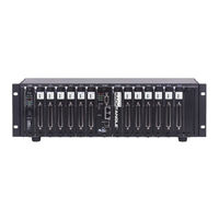
UEi HalfRACK DNR-6-1G-00 User Manual (120 pages)
Data Acquisition Systems
Brand:
UEi
| Category:
Network Hardware
| Size: 3.91 MB
Table of Contents
Table of Contents
3
Chapter 1 Introduction
9
Organization of this Manual
9
Product Versions Described in this Manual
11
Summary of DNR-X-1G/DNR-X-1G-XX Product Versions
11
Chapter 2 The DNR-12-1G Series Racktangle System
12
Powerdnr DNR-12-1G System Overview
12
Typical DNR-12-1G Racktangle System
12
DNR-12-1G Specifications
14
DNR-12-1G Technical Specifications
14
DNR-12-1G Key Features
15
DNR-12-1G Powerdnr Product Features
15
DNR-12-1G Racktangle Enclosure
16
DNR-12-1G Enclosure
16
DNR-12-1G Enclosure Common Components
16
Typical Powerdnr DNR-12 Enclosure (Exploded View)
16
Typical Powerdnr DNR-12 Board Placement
17
Components in Powerdnr DNR-12 Enclosure
17
Optional DNR-IO-Filler Panel for Empty Slots
19
DNR-BRACKET Reversible Mounting Bracket
19
DNR Board Ejection/Insertion Lever Operation
20
DNR-12-1G Cooling Air Flow
21
Air Flow
21
Power, NIC/CPU, and I/O Boards Leds & Controls
22
DNR-12-1G System Front Panel Arrangement
22
DNR-12 Power, NIC/CPU, and I/O Boards Leds & Controls
22
DC Power Module Leds
23
DNR-CPU-1000/-XX Module Leds
23
Typical I/O Module Leds
24
DNR-POWER-DC Module
25
DNR-POWER-DC Module
26
Functional Block Diagram of DNR-POWER-DC Module
27
Functional Block Diagram of DNR-12 Enclosure
28
DNR-CPU/NIC Module
29
DNR-X-1G Series Core Module (CPU/NIC)
29
Device Architecture of DNR Core Module
30
Freescale Powerpc CPU/NIC Controller Architecture
30
Components in Powerdnr Core Module (DNR-CPU-1000 Series)
30
DNR-Buffer Module
32
DNR I/O Boards
32
DNR-12-1G DC Power Thresholds
32
Chapter 3 The DNR-6-1G Series Halfrack System
33
Powerdnr DNR-6-1G System Overview
33
Typical DNR-6-1G Halfrack System
33
DNR-6-1G Specifications
35
DNR-6-1G Technical Specifications
35
DNR-6-1G Key Features
36
DNR-6-1G Halfrack Product Features
36
DNR-6-1G Halfrack Enclosure
37
DNR-6-1G Enclosure
37
Typical Halfrack DNR-6 Enclosure (Exploded View)
37
DNR-6-1G Enclosure Common Components
38
Typical Powerdnr DNR-6 Board Placement
38
Components in Powerdnr DNR-6 Enclosure
38
DNR-6-1G Cooling Air Flow
40
Air Flow
40
Power, NIC/CPU, and I/O Boards Leds & Controls
41
DNR-6-1G System Front Panel Arrangement
41
DNR-6 Power, NIC/CPU, and I/O Boards Leds & Controls
41
DNR-6-1G DNR-POWER-DC Module
42
DNR-6-1G DNR-CPU/NIC Module
42
DNR-6-1G DNR-IO-Modules
42
DNR-6-1G DC Power Thresholds
43
Chapter 4 Installation and Configuration
44
Initial Installation Guide
44
Inspect Package
45
Install Software
45
Initial Boot-Up
47
Typical MTTTY Screen after DNR-X-1G Boot-Up
48
IP Address Overview & Update Procedures
49
When Should You Change the IP Address
49
System Configuration Using Show Command
49
How to Change the Primary IP Address (NIC1)
50
Using Powerdna Explorer to Change IP Address
50
How to Change the Secondary (Diagnostic) IP Address (NIC2)
51
Network Configuration
52
Single DNR-X-1G Direct-Connected to Host Without LAN Switch
52
Single Network for Operation and Diagnostics Using DNR Racks and LAN Switch
52
Example of Configuring Network Settings
53
Separate Networks for Operation and Diagnostics: Two Racks & Two Switches
53
Typical Configuration for a Single DNR-X-1G with a LAN Switch
56
Troubleshooting
57
Updating Firmware
58
Determining Currently Installed Firmware Version
59
Displaying the Version of Your Firmware
59
Updating Firmware Via Powerdna Explorer
60
Update Firmware Menu Item
60
Password Dialog Box
61
Firmware Update Progress Dialog Box
61
Updating Firmware Via Serial Interface
62
Firmware Update Via Serial Port
63
Mounting and Field Connections
64
Physical Dimensions
64
Physical Dimensions of DNR-12 Enclosure
64
Physical Dimensions of DNR-6 Enclosure
65
Pinout Diagrams
66
Network Wiring
66
DNR-X-1G Pinout Diagrams
66
System Configuration with LAN Switch
66
Wiring I/O Boards
67
Repairing (and Upgrading) a DNR System
67
Configuring a NIC Port for Diagnostic Mode
67
Port States
68
List of Functions and Associated Boards
72
Disabling Writes to Flash/Eeprom (NVRAM)
74
Disabling NVRAM Writes
74
DNR-X-1G NIC/CPU Core Module and Carrier
74
NVRAM Protection Jumper
75
Re-Enabling NVRAM Writes
76
Chapter 5 Powerdna Explorer
77
Getting Started with Powerdna Explorer
77
Powerdna Explorer
77
Connecting Powerdna Explorer to Your System
78
Address Ranges to be Scanned
78
Typical Screen for Analog Input Board
79
Overview of the Main Window
80
Menu Bar
80
Powerdna Explorer Main Window
80
Powerdna Explorer Timeout Preferences
80
Address Ranges Dialog Box
81
Edit Address Ranges Dialog Box
81
After a Network >>Scan Network
82
Password Dialog Box for "Store Config" and "Store All Configs
83
Password Dialog Box for "Update Firmware
83
Example of a Hardware Report
84
Example of a Wiring Diagram Display
85
Toolbar
86
Device Tree
86
Powerdna Explorer Toolbar Buttons (Config Level)
86
Powerdna Explorer Toolbar Buttons (Board Level)
86
Example of the Device Tree
87
Settings Panel
88
Example of IOM Settings Panel for Halfrack DNR-6-1G
88
Fields and Descriptions for IOM Settings Panel
88
Example of I/O Device Settings
89
Fields and Descriptions for I/O Device Settings Panel
89
Screen from Network >> Start Reading Input Data
90
Exploring I/O Boards with Powerdna Explorer
91
Digital Input/Output Board Settings
91
Example DIO-403 Inputs
91
Example DIO-403 Outputs
92
Example of DIO-403 Configuration
93
Analog Output Board Settings
94
Example AO-308 Board
94
Analog Input Board Settings
95
Example AI-207 Board
95
Counter/Timer Board Settings
96
Example CT-601 Module
96
Example Quadrature Controls
96
Example bin Counter Controls
97
Example Pulse Width Modulation (PWM) Controls
97
Example Pulse Period Controls
97
Example Frequency Controls
97
Example of Started Counter
98
Chapter 6 Programming CPU Board-Specific Functions
99
Overview
99
Memory Map Overview
99
Memory Map for DNR-X-1G CPU (DNR-CPU-1000)
99
Memory Map for DNR-X-1G-02 CPU (DNR-CPU-1000-02)
100
Memory Map for DNR-X-1G-03 CPU (DNR-CPU-1000-03)
100
Startup Sequence
101
Setting and Reading CPU Core Parameters Via Serial Port
101
Help Command
102
Show System Parameters Command
103
Set and Store Commands
104
Set Parameters
105
TCP/IP Properties
106
Reset DNR-X-1G Command
107
Password Command
108
Display Table of Installed Boards & Logic Version Command
108
Display Power Diagnostics Command
110
Memory Test/Memory Clear Command
111
Clock and Watchdog Access Command
112
Appendix A
113
Location of Fuse for Base Boards Equipped with a Fuse
117
DNA/DNR Replacement Fuses
117
Appendix B
117
Location of Fuses for DNR-POWER-DC Board
118
Location of Fuses for DNR-POWER-1GB Board
118
Index
119
Advertisement
Advertisement
Related Products
UEi HalfRACK DNR-6-1G Series
UEi HalfRACK DNR-6-1G-01
UEi HalfRACK DNR-6-1G-02
UEi HalfRACK DNR-6-1G-03
UEi RACKtangle DNR-12-1G Series
UEi RACKtangle DNR-12-1G-00
UEi RACKtangle DNR-12-1G-01
UEi RACKtangle DNR-12-1G-02
UEi RACKtangle DNR-12-1G-03
UEi DM391
UEi Categories
Measuring Instruments
Test Equipment
Thermometer
Multimeter
Security Sensors
More UEi Manuals
Login
Sign In
OR
Sign in with Facebook
Sign in with Google
Upload manual
Upload from disk
Upload from URL