
Subscribe to Our Youtube Channel
Summary of Contents for UEi RACKtangle DNR-12-1G Series
- Page 1 DNR-12-1G Series RACKtangle DNR-6-1G Series HalfRACK Data Acquisition Systems — User Manual October 2018 PN Man-DNR-X-1G © Copyright 1998-2018 United Electronic Industries, Inc. All rights reserved.
- Page 2 Specifications in this document are subject to change without notice. Check with UEI for current status.
-
Page 3: Table Of Contents
DNR-X-1G Series RACKtangle and HalfRACK Systems Table of Contents Table of Contents Chapter 1 Introduction ........... . 1 Organization of This Manual . - Page 4 DNR-X-1G Series RACKtangle and HalfRACK Systems Table of Contents 4.3.1 When Should You Change the IP Address? ......41 4.3.2 How to Change the Primary IP Address (NIC1).
- Page 5 DNR-X-1G Series RACKtangle and HalfRACK Systems Table of Contents 6.4.8 Memory Test/Memory Clear Command ......103 6.4.9 Monitor CPU and Pbuf Usage Command .
- Page 6 DNR-X-1G Series RACKtangle and HalfRACK Systems List of Figures List of Figures Chapter 1 Introduction ........... . . 1 Chapter 2 The DNR-12-1G Series RACKtangle System .
- Page 7 DNR-X-1G Series RACKtangle and HalfRACK Systems List of Figures Chapter 5 PowerDNA Explorer ..........69 PowerDNA Explorer ....................69 Address Ranges to be Scanned ..................70 Typical Screen for Analog Input Board ................71...
- Page 8 DNR-X-1G Series RACKtangle and HalfRACK Systems List of Figures List of Tables Chapter 1 Introduction ........... . . 1 Summary of DNR-X-1G/DNR-X-1G-XX Product Versions ...........3 Chapter 2 The DNR-12-1G Series RACKtangle System .
-
Page 9: Chapter 1 Introduction
DNR-X-1G system. • Chapter 5 – PowerDNA Explorer This chapter provides a general description of the menus and screens of UEI’s GUI-based communication application, PowerDNA Explorer, when used with a DNR-X-1G system. • Chapter 6 – Programming CPU Board-specific Functions This chapter describes tools and facilities used for programming board- specific functions. - Page 10 Failure to do so may cause severe damage to the equipment. No HOT SWAP Always turn POWER OFF before performing maintenance on a UEI system. Failure to observe this warning may result in damage to the equipment and possible injury to personnel.
-
Page 11: Product Versions Described In This Manual
DNR-X-1G Series RACKtangle and HalfRACK Systems Chapter 1 Introduction Product This user manual provides documentation for the DNR-X-1G series data acquisition systems: DNR-X-1G, DNR-X-1G-02, and DNR-X-1G-03 product Versions versions. Described in Each product version is available in a DNR-12-1G RACKtangle chassis or a This Manual DNR-6-1G HalfRACK chassis. -
Page 12: Chapter 2 The Dnr-12-1G Series Racktangle System
NOTE: For a list of product versions available for the DNR-12-1G Series RACKtangle systems, refer to Section 1.2 on page 3. PowerDNR UEI PowerDNR DNR-12-1G RACKtangle systems are rack-mounted versions DNR-12-1G of the PowerDNA Cube Ethernet-based data acquisition systems. - Page 13 NOTE: For detailed descriptions of all I/O boards and accessories available for DNR-X-1G systems, refer to www.ueidaq.com. UEI stand-alone systems (UEIPAC, UEISIM, UEIModbus, and UEIOPCUA deployments) are also available for use with DNR-12-1G RACK systems: • UEIPAC 1200R - Programmable Automation Controller •...
-
Page 14: Dnr-12-1G Specifications
DNR-X-1G Series RACKtangle and HalfRACK Systems Chapter 2 The DNR-12-1G Series RACKtangle System DNR-12-1G Figure 2-2 lists the technical specifications of the DNR-12-1G PowerDNR system. Specifi- cations Standard Interfaces To Host Computer Two independent 1000Base-T Gigabit Ethernet ports (100/10Base-T compatible) Distance from host 100 meters, max Other Interfaces... -
Page 15: Dnr-12-1G Key Features
48 RS-232/422/485 ports per rack Low Power: Less than 13 watts per typical rack (not including I/O) AC, 9-36 VDC or battery powered Stand alone Modes Upgradeable to UEI 1200R Upgradeable to UEI 1200R Upgradeable to UEIModbus 1200R Rugged and Industrial:... -
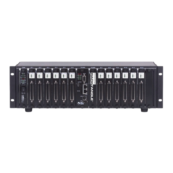
Page 16: Dnr-12-1G Racktangle Enclosure
DNR-X-1G Series RACKtangle and HalfRACK Systems Chapter 2 The DNR-12-1G Series RACKtangle System DNR-12-1G This section describes the DNR-12-1G chassis and provides an overview of common components included in every DNR-12-1G system. RACKtangle Enclosure 2.4.1 DNR-12-1G The DNR-12 enclosure is a rigid mechanical structure with complete EMI shielding (see Figure 2-4 below). -
Page 17: Typical Powerdnr Dnr-12 Board Placement
/ not included in price of rack) Fans Four 8-volt cooling fans mounted on the rear of the enclosure (see Figure 2-9 for air flow diagram) All UEI modules are available in both PowerDNA and Power DNR package designs. © Copyright 2018 October 2018 www.ueidaq.com... - Page 18 DNR-X-1G Series RACKtangle and HalfRACK Systems Chapter 2 The DNR-12-1G Series RACKtangle System 2.4.2.1 Physical A feature of the DNR-X-1G design is that the address of a module is determined by the position of the module within the enclosure, numbered from left to right. A Addressing of typical module address is: DNR-12-1G...
-
Page 19: Optional Dnr-Io-Filler Panel For Empty Slots
DNR-X-1G Series RACKtangle and HalfRACK Systems Chapter 2 The DNR-12-1G Series RACKtangle System 2.4.2.2 DNR-IO- The following section provides drawings for the DNR-IO-FILLER, DNR-BRACKET, and DNR- I/O board extraction lever as found in DNR-X-1G FILLER, DNR- systems. BRACKET, & DNR- I/O Board Drawings Grounding... -
Page 20: Dnr Board Ejection/Insertion Lever Operation
DNR-X-1G Series RACKtangle and HalfRACK Systems Chapter 2 The DNR-12-1G Series RACKtangle System Lift Lever to eject board from backplane connector Press lever down to insert board into backplane connector Figure 2-8. DNR Board Ejection/Insertion Lever Operation © Copyright 2018 October 2018 www.ueidaq.com United Electronic Industries, Inc. -
Page 21: Dnr-12-1G Cooling Air Flow
DNR-X-1G Series RACKtangle and HalfRACK Systems Chapter 2 The DNR-12-1G Series RACKtangle System 2.4.3 DNR-12-1G As shown below in Figure 2-9, cooling air is drawn into the rear of the enclosure via four fans, routed forward over the electronic circuit boards, up to the top of Cooling Air the enclosure, and then out the top rear of the enclosure. -
Page 22: Power, Nic/Cpu, And I/O Boards Leds & Controls
DNR-X-1G Series RACKtangle and HalfRACK Systems Chapter 2 The DNR-12-1G Series RACKtangle System DNR-12 DNR-12-1G LED indicators are illustrated in Figure 2-10. Power, NIC/ The power, CPU, and I/O board LEDs are individually described in Figure 2-11, CPU, and I/O Figure 2-12, and Figure 2-13 respectively. -
Page 23: Dc Power Module Leds
DNR-X-1G Series RACKtangle and HalfRACK Systems Chapter 2 The DNR-12-1G Series RACKtangle System LED ON/Off means: LED ON/OFF means: Input Voltage OK/Error Input Current OK/High 1.5VDC OK/Error Fans On/Off User Controlled/Off (default) I/O Circuit OK (flashes 1/sec)) When flashing, module needs Temp High/OK attention 24VDC OK/Error -- Modules 1-6... -
Page 24: Typical I/O Module Leds
DNR-X-1G Series RACKtangle and HalfRACK Systems Chapter 2 The DNR-12-1G Series RACKtangle System Ready (Power ON) Status Figure 2-13. Typical I/O Module LEDs © Copyright 2018 October 2018 www.ueidaq.com United Electronic Industries, Inc. 508.921.4600... -
Page 25: Dnr-Power-Dc Module
DNR-X-1G Series RACKtangle and HalfRACK Systems Chapter 2 The DNR-12-1G Series RACKtangle System DNR-POWER- The DNR-POWER-DC Module is a dedicated DC/DC source and control module available only for use with a PowerDNR rack enclosure. It is always DC Module mounted in the leftmost slot of the DNR chassis and is recognized on the PowerDNR bus with an ID of 0x020 at address 0xA00C0000. -
Page 26: Dnr-Power-Dc Module
DNR-X-1G Series RACKtangle and HalfRACK Systems Chapter 2 The DNR-12-1G Series RACKtangle System Indicating LEDs Ejection Lever On/Off Switch Power Connector Grounding Fingers (hidden) Figure 2-14. DNR-POWER-DC Module © Copyright 2018 October 2018 www.ueidaq.com United Electronic Industries, Inc. 508.921.4600... -
Page 27: Functional Block Diagram Of Dnr-Power-Dc Module
DNR-X-1G Series RACKtangle and HalfRACK Systems Chapter 2 The DNR-12-1G Series RACKtangle System A functional block diagram of the DNR-POWER-DC Module is shown in Figure 2-15 below. Input Voltage Source 9-36 VDC @ 80 W max. 3.3V DC/DC Input Current Monitor 2.5V LDO 1.5V DC/DC... -
Page 28: Functional Block Diagram Of Dnr-12 Enclosure
DNR-X-1G Series RACKtangle and HalfRACK Systems Chapter 2 The DNR-12-1G Series RACKtangle System The input current and all output voltages, including the +2.5, +3.3, and +24 VDC from the NIC module, plus signals from the two temperature sensors mounted within the enclosure, are input to a 24-bit delta-sigma A/D converter. Except for Vin, the voltage sources use 1:23.1 dividers on the front end. -
Page 29: Dnr-Cpu/Nic Module
DNR-X-1G Series RACKtangle and HalfRACK Systems Chapter 2 The DNR-12-1G Series RACKtangle System DNR-CPU/NIC The DNR-CPU/NIC Core Module (DNR-CPU-1000, DNR-CPU-1000-02, or Module DNR-CPU-1000-03) occupies two slots of a DNR-X-1G RACKtangle enclosure. The DNR-CPU/NIC Core module consists of a Freescale (formerly Motorola) MPC8347 or MPC8347E 32-bit 400 MHz CPU and peripheral devices (USB 2.0, RS-232, NIC, SD, etc) for use with a Gigabit Ethernet communication network and an internal 66 MHz 32-bit common logic interface bus. -
Page 30: Device Architecture Of Dnr Core Module
DNR-X-1G Series RACKtangle and HalfRACK Systems Chapter 2 The DNR-12-1G Series RACKtangle System 2.7.1 Device Figure 2-17 shows the architecture of the DNR-CPU-1000 Series Core Modules: Architecture of DNR Core Module 32-bit 66-MHz bus FLASH 1000-BASE-T RJ-45 DDR2 FPGA RJ-45 PPC 8347 Power In DC/DC... - Page 31 DNR-X-1G Series RACKtangle and HalfRACK Systems Chapter 2 The DNR-12-1G Series RACKtangle System Table 2-2 Components in PowerDNR Core Module (DNR-CPU-1000 Series) Item Description 128 MB or 256 MB DNR-X-1G (-00/-01) systems provide 128 MB of RAM (DNR-CPU-1000). DNR-X-1G-02 systems provide 256 MB of RAM (DNR-CPU-1000-02). of SDRAM DNR-X-1G-03 systems provide 256 MB of RAM (DNR-CPU-1000-03).
-
Page 32: Dnr-Buffer Module
PowerDNA Cube. Refer to the datasheets and user manuals for detailed electrical specifications, board descriptions, and user instructions for I/O boards. These documents are available on the UEI website at www.ueidaq.com. 2.10 DNR-12-1G Table 2-1 lists the DC power threshold specifications for DNR-12-1G 12-slot RACKtangle systems. -
Page 33: Chapter 3 The Dnr-6-1G Series Halfrack System
NOTE: For the list of product versions available for the DNR-6-1G Series HalfRACK systems, refer to Section 1.2 on page 3. PowerDNR UEI DNR-6-1G HalfRACK systems are identical to the DNR-12-1G systems DNR-6-1G except for the size of the enclosure and the number and order of I/O boards that can be accepted. - Page 34 NOTE: For detailed descriptions of all I/O boards and accessories available for DNR-X-1G systems, refer to www.ueidaq.com. UEI stand-alone systems (UEIPAC, UEISIM, UEIModbus, and UEIOPCUA deployments) are also available for use with DNR-6-1G RACK systems: • UEIPAC 600R - Programmable Automation Controller •...
-
Page 35: Dnr-6-1G Specifications
DNR-X-1G Series RACKtangle and HalfRACK Systems Chapter 3 The DNR-6-1G Series HalfRACK System DNR-6-1G The technical specifications of the DNR-6-1G system are listed below. Specifi- cations Standard Interfaces To Host Computer Two independent 1000Base-T Gigabit Ethernet ports (100/10Base-T compatible) Distance from host 100 meters, max Config/General RS-232, 9-pin “D”... -
Page 36: Dnr-6-1G Key Features
24 RS-232/422/485 ports per rack Low Power: Less than 13 watts per typical rack (not including I/O) AC, 9-36 VDC or battery powered. Stand alone Modes Upgradeable to UEI 600R Upgradeable to UEI 600R Upgradeable to UEIModbus 600R Rugged and Industrial:... -
Page 37: Dnr-6-1G Halfrack Enclosure
Also note, rubber feet are supplied for desktop or tabletop mounting. If rack mounting is desired, UEI recommends using a shelf for mounting in a 19 inch enclosure. Refer to Section 4.7 on page 56 for more information about mounting and field connections. -
Page 38: Dnr-6-1G Enclosure Common Components
Fans Three 8-volt cooling fans mounted on the rear of the enclosure (see Figure 3-4 and Section 3.4.3 for air flow diagram) All UEI PowerDNA modules are available in both PowerDNA and Power DNR package designs. © Copyright 2018 October 2018 www.ueidaq.com... - Page 39 DNR-X-1G Series RACKtangle and HalfRACK Systems Chapter 3 The DNR-6-1G Series HalfRACK System 3.4.2.1 Physical A feature of the DNR-6-1G design is that the address of a module is determined by the position of the module within the enclosure, numbered from left to right. A Addressing of typical module address is: DNR-6-1G...
-
Page 40: Dnr-6-1G Cooling Air Flow
DNR-X-1G Series RACKtangle and HalfRACK Systems Chapter 3 The DNR-6-1G Series HalfRACK System 3.4.3 DNR-6-1G As shown in Figure 3-6 below, cooling air is drawn into the rear of the enclosure via three fans, routed forward over the electronic circuit boards, up to the top of Cooling Air the enclosure, and then out the top rear of the enclosure. -
Page 41: Power, Nic/Cpu, And I/O Boards Leds & Controls
DNR-X-1G Series RACKtangle and HalfRACK Systems Chapter 3 The DNR-6-1G Series HalfRACK System DNR-6 Power, DNR-6-1G LED indicators are illustrated in Figure 3-7. NIC/CPU, and Note that modules used in both DNR-6 and DNR-12 systems are identical, I/O Boards except that the DNR-6 enclosure only accepts six I/O boards. The power, CPU, and I/O board LEDs are individually described in “DNR-12 Power, NIC/CPU, and LEDs &... -
Page 42: Dnr-6-1G Dnr-Power-Dc Module
DNR-6 or DNR-12 enclosure; PowerDNA modules can be inserted only into a PowerDNA Cube. Refer to the datasheets and user manuals for detailed electrical specifications, board descriptions, and user instructions for I/O boards. These documents are available on the UEI website at www.ueidaq.com. © Copyright 2018 October 2018 www.ueidaq.com... -
Page 43: Dnr-6-1G Dc Power Thresholds
DNR-X-1G Series RACKtangle and HalfRACK Systems Chapter 3 The DNR-6-1G Series HalfRACK System DNR-6-1G DC Table 5-1 lists the DC power threshold specifications for DNR-6-1G HalfRACK systems. Power Thresholds Table 5-1 DC Power Thresholds for DNR-6-1G HalfRACK Systems Backplane Turn-on Turn-off Power Rail Reset... -
Page 44: Chapter 4 Installation And Configuration
DNR-X-1G Series RACKtangle and HalfRACK Systems Chapter 4 Installation and Configuration Chapter 4 Installation and Configuration The following installation and configuration topics are included in this chapter: • Initial Installation Guide (Section 4.1) • Initial Boot-up (Section 4.2) • IP Address Overview & Update Procedures (Section 4.3) •... -
Page 45: Inspect Package
PowerDNA Software Suite A. Software Install: Windows The PowerDNA CD provides one installer that combines the UEI low-level driver and UEIDAQ Framework. Be sure to install third-party applications (such as LabVIEW, MATLAB, or Visual Studio) before installing the PowerDNA Software Suite. - Page 46 DNR-X-1G Series RACKtangle and HalfRACK Systems Chapter 4 Installation and Configuration STEP 2: Follow the prompts, and then choose a PowerDNA Software Suite Setup Type. Unless you are an expert user and have specific requirements, select Typical Installation and accept the default configuration. The Software Suite installer automatically installs any required tools and plugins.
-
Page 47: Initial Boot-Up
DNR-X-1G Series RACKtangle and HalfRACK Systems Chapter 4 Installation and Configuration Initial Boot-up Perform an initial boot in preparation for configuring the network using the following procedure: STEP 1: Familiarize yourself with your DNR system front-panel layout. Note that all connections are made on the front of the unit;... -
Page 48: Typical Mttty Screen After Dnr-X-1G Boot-Up
DNR-X-1G Series RACKtangle and HalfRACK Systems Chapter 4 Installation and Configuration Figure 4-1. Typical MTTTY Screen after DNR-X-1G Boot-up The boot process displays the model, serial number, and slot positions of boards in the rack enclosure. You can also type show <CR> at the DQ> prompt to display information about the system configuration, as shown in Figure 4-2. -
Page 49: Ip Address Overview & Update Procedures
This section describes when and how to change the default IP addresses. 4.3.1 When Should You should change your IP address if you have multiple UEI chassis in your application or if your application has network addressing guidelines you must You Change conform to. -
Page 50: How To Change The Primary Ip Address (Nic1)
Chapter 4 Installation and Configuration 4.3.2 How to You can use PowerDNA Explorer (a UEI-developed GUI application) or a serial terminal program to change the IP address. Change the Primary IP The first step in changing the IP address is to consult your system or network administrator to obtain unused IP addresses. -
Page 51: How To Change The Secondary (Diagnostic) Ip Address (Nic2)
DNR-X-1G Series RACKtangle and HalfRACK Systems Chapter 4 Installation and Configuration 4.3.2.2 Update IP To update the IP address on your DNR-X-1G over the serial port, you must first establish serial communication between your host PC and chassis. Address via Serial Port To set up communication over the serial port, do the following: a. -
Page 52: Network Configuration
DNR-X-1G Series RACKtangle and HalfRACK Systems Chapter 4 Installation and Configuration Network If you do not need to connect to a company LAN and have only a single DNR-X-1G in your system, you can connect it directly to your host as shown in Configuration Figure 4-4 below. -
Page 53: Example Of Configuring Network Settings
DNR-X-1G Series RACKtangle and HalfRACK Systems Chapter 4 Installation and Configuration Figure 4-6 shows a two-rack dual network system with two LAN switches that performs both data acquisition and diagnostic functions. NIC1 - to Intranet NIC2 - to diagnostic ports) Figure 4-6. - Page 54 DNR-X-1G Series RACKtangle and HalfRACK Systems Chapter 4 Installation and Configuration IP Addressing Side Note: The range of usable addresses is defined by the IP address and subnet mask. • An IP address is a number that lies within the range of 0.0.0.0 and 255.255.255.255. In the ipconfig example shown in step 1, the IP address is 192.168.1.10.
- Page 55 DNR-X-1G Series RACKtangle and HalfRACK Systems Chapter 4 Installation and Configuration d. Open the Command Prompt: Start >> Programs >> (Accessories >>) Command Prompt ipconfig e. Type at the Command Prompt to confirm the network configuration on the host PC: C:\>...
-
Page 56: Typical Configuration For A Single Dnr-X-1G With A Lan Switch
DNR-X-1G Series RACKtangle and HalfRACK Systems Chapter 4 Installation and Configuration STEP 5: Connect the DNR-X-1G to your PC’s second NIC using a CAT5 cable. The green LEDs on the DNR-X-1G NIC2 should light up. STEP 6: Ping the DNR-X-1G system from the command prompt on the host PC to make sure that it is alive (the following shows a successful response): C:\>... -
Page 57: Troubleshooting
• Note “show” results, and verify computers are on a valid subnet and have valid IPs. Reboot the DNR-X-1G system. The start-up screen should display upon restart. If you have questions, contact UEI support at support@ueidaq.com. © Copyright 2018 October 2018 www.ueidaq.com United Electronic Industries, Inc. 508.921.4600... -
Page 58: Updating Firmware
PowerDNA Software Suite, available for download at any time from the UEI web site (www.ueidaq.com). To locate the latest UEI firmware after installing the PowerDNA Software Suite, browse to the installation’s Firmware directory, (e.g. C:\Program Files (x86)\UEI\PowerDNA\Firmware). -
Page 59: Determining Currently Installed Firmware Version
If the FW Ver has a yellow triangle with an exclamation point next to it (see figure above), you have a mismatch between the firmware installed on your RACK system and the software version on your host PC. If you see this warning, UEI highly recommends that you update your firmware to match your software (or software to match your firmware). -
Page 60: Updating Firmware Via Powerdna Explorer
Installation and Configuration 4.6.2 Updating Before using a new release of UEI libraries and applications to communicate with your system, you should install the latest version of the firmware onto the Firmware via CPU core module in your RACK. Mismatched versions can cause operational PowerDNA errors. -
Page 61: Password Dialog Box
DNR-X-1G Series RACKtangle and HalfRACK Systems Chapter 4 Installation and Configuration STEP 9: If asked, enter the password to continue. UEI cube and RACK systems come with the default password set to powerdna. powerdna Figure 4-10. Password Dialog Box STEP 10: Wait for the progress dialog to complete. The system will then be updated and running the new firmware. -
Page 62: Updating Firmware Via Serial Interface
DNR-X-1G Series RACKtangle and HalfRACK Systems Chapter 4 Installation and Configuration 4.6.3 Updating The following section provides the procedure for uploading firmware over the DNR-X-1G RACK serial port using a serial terminal client. In this procedure, we Firmware via use MTTTY as the serial terminal client; however, any serial terminal application Serial can be used to upload the ROM image. -
Page 63: Firmware Update Via Serial Port
Transfer » Send a. In the MTTTY menu bar, select File. b. Navigate to your UEI installation, and select the image file: \Program Files (x86)\UEI\PowerDNA\Firmware\Firmware_PPC_1G\rom8347_4_x_y.mot NOTE: A progress bar will appear in the lower left corner of MTTTY, indicating progress. -
Page 64: Mounting And Field Connections
For flat vertical surfaces, the DNR-6-1G can be mounted with the flange mounts; however, since the DNR-6-1G is not 19” wide, UEI recommends using a shelf for rack installations. -
Page 65: Physical Dimensions Of Dnr-6 Enclosure
10.50 in. (side view) (front view) Note: For wall mounting, align flanges flush with rear of enclosure. For rack mounting, UEI recommends using a shelf with DNR-6-1G systems. Figure 4-14. Physical Dimensions of DNR-6 Enclosure © Copyright 2018 October 2018 www.ueidaq.com... -
Page 66: Pinout Diagrams
DNR-X-1G Series RACKtangle and HalfRACK Systems Chapter 4 Installation and Configuration 4.7.2 Pinout Pinout diagrams for the power molex, synchronization port, and RS-232 serial port connectors are shown below in Figure 4-15. Diagrams Power In Serial (RS-232) (molex) +VIN TXD– +VIN RXD–... -
Page 67: Wiring I/O Boards
If you want to enhance, repair, or otherwise modify a specific I/O board, however, you must send the module back to the factory or to your local distributor. This process requires that you request an RMA number from UEI before shipping. To do so, contact support@ueidaq.com and provide the following information: 1. -
Page 68: Port States
DNR-X-1G Series RACKtangle and HalfRACK Systems Chapter 4 Installation and Configuration The following standard DAQBIOS commands are accessible on the diagnostics port whenever one or more I/O boards are in operating mode: DQCMD_ECHO // echo DQCMD_RDCFG // read configuration (new) DQCMD_RDSTS // read status DQCMD_WRCHNL (selected)//write channel... - Page 69 DNR-X-1G Series RACKtangle and HalfRACK Systems Chapter 4 Installation and Configuration DQCMD_RDCFG This command returns the current configuration of the specified board(s): int DAQLIB DqCmdReadCfg(int Iom, DQRDCFG pDQRdCfg[], uint32 maxsize, uint32* entries) int Iom // a pointer to the DQIOME structure DQRDCFG pDQRdCfg[] // structure that contains board configuration uint32 maxsize...
- Page 70 DNR-X-1G Series RACKtangle and HalfRACK Systems Chapter 4 Installation and Configuration /* state flags */ #define STS_STATE_TS_SH #define STS_STATE_TS_SH_INS(S,TS,MD) ((S & 0xffff00f0)|((TS<<8) & 0xff00)|(MD&0xf)) #define STS_STATE_STICKY The second word describes the status of the board. It is written when the board enters initialization mode and remains unchanged until the next reboot.
- Page 71 DNR-X-1G Series RACKtangle and HalfRACK Systems Chapter 4 Installation and Configuration The fourth word contains the status of the firmware. A board operating normally does not have any flags set except STS_FW_CONFIG_DONE, which means the board was properly configured before entering operating mode (it is cleared upon re-entering configuration mode) and STS_FW_OPER_MODE, which means that the board switched into operating mode without any errors.
-
Page 72: List Of Functions And Associated Boards
DNR-X-1G Series RACKtangle and HalfRACK Systems Chapter 4 Installation and Configuration DQCMD_IOCTL This command is used to retrieve data from the board. When a port is in diagnostic mode, it returns current data but cannot reprogram the channel list. The channel list is used to inform the handler the ID of the channel from which data should be retrieved. - Page 73 DNR-X-1G Series RACKtangle and HalfRACK Systems Chapter 4 Installation and Configuration Sequence of Operation To use the diagnostic port without affecting performance of the main port, UEI recommends that you use the following sequence of operations: 1. Open main port. 2. Open diagnostics port.
-
Page 74: Disabling Writes To Flash/Eeprom (Nvram)
Note that installing the NVRAM protection jumper requires the DNR-CPU-1000/ DNR-CPU-1000-XX module in the DNR-X-1G chassis to have a PCB board removed and replaced. In general UEI does not recommend that users remove PCB boards from their carriers: over-torquing screws or bending PCB boards can permanently damage the DNR-CPU-1000 modules. -
Page 75: Nvram Protection Jumper
DNR-X-1G Series RACKtangle and HalfRACK Systems Chapter 4 Installation and Configuration CAUTION! Care must be taken when removing PCB boards from carrier. Over-tightening or forcing hardware can crack boards, damage components and/or leave the DNR- NIC/CPU module inoperable. STEP 3: To remove the lower PCB board from the carrier, do the following: a. -
Page 76: Re-Enabling Nvram Writes
DNR-X-1G Series RACKtangle and HalfRACK Systems Chapter 4 Installation and Configuration d. Slide and align retained large plastic spacer between lower and upper boards. e. From the bottom of the carrier, insert the retained Phillips screw (4-40 x 1 inch) through the carrier, small plastic spacer, lower PCB board, large plastic spacer, and upper PCB board. -
Page 77: Chapter 5 Powerdna Explorer
(<PowerDNA-x.y.z>/explorer) by typing: • java -jar PowerDNAExplorer.jar NOTE: UEI provides a PowerDNA Explorer DEMO with the installation that lets you safely explore the menus and I/O board screens without using actual hardware. DEMOs are located in the same directories as the PowerDNA Explorer executables. -
Page 78: Connecting Powerdna Explorer To Your System
DNR-X-1G Series RACKtangle and HalfRACK Systems Chapter 5 PowerDNA Explorer 5.1.1 Connecting PowerDNA Explorer has the capability of identifying DNR-X-1G rack systems (or PPCx/PPCx-1G Cubes) on a selected network. Using PowerDNA Explorer, you PowerDNA scan the network, and discovered systems are listed in the left-hand pane of the Explorer to display. -
Page 79: Typical Screen For Analog Input Board
DNR-X-1G Series RACKtangle and HalfRACK Systems Chapter 5 PowerDNA Explorer STEP 3: Click Network >> Scan Network to scan the LAN for DNR-X-1G systems or cubes within the range specified in the previous step. One or more gray icons will display in the left-hand-side of the screen. If no icons are displayed, refer to the Troubleshooting section in the previous chapter (Section 4.5). -
Page 80: Overview Of The Main Window
DNR-X-1G Series RACKtangle and HalfRACK Systems Chapter 5 PowerDNA Explorer Overview of The Main Window of the PowerDNA Explorer is shown in Figure 5-4 and consists of four primary sections: the Main Window • The Menu Bar (described in Section 5.2.1) •... -
Page 81: Address Ranges Dialog Box
Network >> Scan Network scans the network for devices and populates the device tree. How much of the network is scanned depends on the settings in the Network for Network Ranges dialog. UEI Chassis © Copyright 2018 October 2018 www.ueidaq.com United Electronic Industries, Inc. -
Page 82: After A Network >>Scan Network
DNR-X-1G Series RACKtangle and HalfRACK Systems Chapter 5 PowerDNA Explorer Figure 5-8. After a Network >>Scan Network In the example shown above in Figure 5-8, after Network >> Scan Network was clicked, the DNR-X-1G chassis labeled “IOM-12345” was found and displays in the Device Tree panel. -
Page 83: Password Dialog Box For "Store Config" And "Store All Configs
DNR-X-1G Series RACKtangle and HalfRACK Systems Chapter 5 PowerDNA Explorer Figure 5-9. Password Dialog Box for “Store Config” and “Store All Configs” assword dialog box for Store Config and Store All Configs Password dialog box for Update Firmware... Figure 5-10. Password Dialog Box for “Update Firmware . . .” ©... -
Page 84: Example Of A Hardware Report
DNR-X-1G Series RACKtangle and HalfRACK Systems Chapter 5 PowerDNA Explorer 5.2.1.3 View Menu This section describes items under the View Menu. 5.2.1.3.1 Obtaining a View >> Show Hardware Report displays hardware information for your PowerDNA system.. Report of DNR-X-1G Hardware Figure 5-11. -
Page 85: Example Of A Wiring Diagram Display
DNR-X-1G Series RACKtangle and HalfRACK Systems Chapter 5 PowerDNA Explorer 5.2.1.3.2 Showing the View >> Show Wiring Diagram displays connector pins for a specific board. All boards have this feature. The AI-207 is displayed below as an example. The Wiring wiring diagrams in PowerDNA Explorer match the wiring diagrams in the Diagram for an following sections. -
Page 86: Toolbar
DNR-X-1G Series RACKtangle and HalfRACK Systems Chapter 5 PowerDNA Explorer 5.2.2 Toolbar The toolbar contains the following buttons: • Scan Network, Show Hardware Report, Reload Config, Store Config, Store All Configs (shown in Figure 5-13) • Start Reading Input Data, View User Manual, Visit Documentation Download Page, and View Wiring Diagram (shown in Figure 5-14) Toolbar buttons duplicate the functionality of the corresponding menu items described in the Menu Bar sections above. -
Page 87: Example Of The Device Tree
DNR-X-1G Series RACKtangle and HalfRACK Systems Chapter 5 PowerDNA Explorer Each item has an icon indicating whether it is a central controller, IOM (rack or Cube), or board. The text label for each item is the device's model number, name, and serial number. Boards are also labeled with their position number in brackets. -
Page 88: Settings Panel
DNR-X-1G Series RACKtangle and HalfRACK Systems Chapter 5 PowerDNA Explorer 5.2.4 Settings Panel The settings panel presents a set of controls that allows you to change the settings of the device currently selected in the device tree or allows you to view acquired input data for the device selected. -
Page 89: Example Of I/O Device Settings
DNR-X-1G Series RACKtangle and HalfRACK Systems Chapter 5 PowerDNA Explorer 5.2.4.2 I/O Device / Figure 5-17 provides an overview of the screen for displaying I/O device settings. Setting options vary for I/O boards on a per-board basis. The example Board Settings below show settings for the AI-217 analog input board. -
Page 90: Screen From Network >> Start Reading Input Data
DNR-X-1G Series RACKtangle and HalfRACK Systems Chapter 5 PowerDNA Explorer Figure 5-18. Screen from Network >> Start Reading Input Data 5.2.4.2.1 Interacting To read data from an I/O board, select Network >> Start Reading Input Data. The Value column for any inputs will update, as shown above in the settings panel. with I/O Boards Also in the settings panel, you can add or edit channel names. -
Page 91: Exploring I/O Boards With Powerdna Explorer
Counter/Timer Board Settings (Section 5.3.4) NOTE: Examples in this section are an introduction to PowerDNA Explorer capabilities; please note PowerDNA Explorer provides a communication link with all types of UEI I/O boards, not just the board-types listed in this section. 5.3.1... -
Page 92: Example Dio-403 Outputs
DNR-X-1G Series RACKtangle and HalfRACK Systems Chapter 5 PowerDNA Explorer Input/Output/Configuration/Initialization/Shutdown tabs switch between displaying DIO pin reading of input state data, setting DIO output state, configuring DIO as output or input, and settings for initial and shutdown states. The Input tabs contain the following columns: •... -
Page 93: Example Of Dio-403 Configuration
DNR-X-1G Series RACKtangle and HalfRACK Systems Chapter 5 PowerDNA Explorer Figure 5-21. Example of DIO-403 Configuration The Configuration tab gets/sets the current input/output directions per port. It contains the following columns: • Name is the channel (port) name, or a user-defined string. •... -
Page 94: Analog Output Board Settings
DNR-X-1G Series RACKtangle and HalfRACK Systems Chapter 5 PowerDNA Explorer 5.3.2 Analog Output This section provides an overview of PowerDNA Explorer settings for analog output boards. Each type of analog output board will have displays specific to Board the features offered with that board. In this section, we use the AO-308 as an Settings example. -
Page 95: Analog Input Board Settings
DNR-X-1G Series RACKtangle and HalfRACK Systems Chapter 5 PowerDNA Explorer 5.3.3 Analog Input This section provides an overview of PowerDNA Explorer settings for analog input boards. Each type of analog input board will have displays specific to the Board features offered with that board. In this section, we use the AI-207 as an Settings example. -
Page 96: Counter/Timer Board Settings
DNR-X-1G Series RACKtangle and HalfRACK Systems Chapter 5 PowerDNA Explorer 5.3.4 Counter/Timer This section provides an overview of PowerDNA Explorer settings for counter/ timer boards. Each type of I/O board will have displays specific to the features Board offered with that board. In this section, we use the CT-601 as an example. Settings Figure 5-24. -
Page 97: Example Bin Counter Controls
DNR-X-1G Series RACKtangle and HalfRACK Systems Chapter 5 PowerDNA Explorer Example Bin Counter controls Figure 5-26. Example Bin Counter Controls Example Bin Counter controls Example Pulse Width Modulation (PWM) controls Figure 5-27. Example Pulse Width Modulation (PWM) Controls Figure 5-28. Example Pulse Period Controls Figure 5-29. -
Page 98: Example Of Started Counter
DNR-X-1G Series RACKtangle and HalfRACK Systems Chapter 5 PowerDNA Explorer Present Value of Count Figure 5-30. Example of Started Counter While the board is running, you can choose Network >> Store Config to retrieve runtime values from the counter, which will display in the read-only text field(s) of the counter control panel. -
Page 99: Chapter 6 Programming Cpu Board-Specific Functions
DNR-X-1G Series RACKtangle and HalfRACK Systems Chapter 6 Programming CPU Board-specific Functions Chapter 6 Programming CPU Board-specific Functions Overview This chapter provides information about programming DNR-X-1G CPU Core modules: • Memory Map Overview (Section 6.2) • Startup Sequence (Section 6.3) •... -
Page 100: Memory Map For Dnr-X-1G-02 Cpu (Dnr-Cpu-1000-02)
DNR-X-1G Series RACKtangle and HalfRACK Systems Chapter 6 Programming CPU Board-specific Functions Table 6-2 Memory Map for DNR-X-1G-02 CPU (DNR-CPU-1000-02) Start Device Address End Address Size Description SDRAM 0xFFFFFFF 256MB SDRAM_ADDRESS Exception table 0x3000 12 kB Processor address map CPU card address 0xA00E0000 0xA00EFFFC 64 kB EXT_SRAM_ADDRESS... -
Page 101: Startup Sequence
Set up your terminal to the proper serial port, 57600 bit rate, no parity, eight data bits, and one stop bit. NOTE: To use the MTTTY executable included with the UEI installation, open mttty.exe in the following directory on Windows machines, and then click Connect: \Program Files(x86)\UEI\PowerDNA\Firmware\mttty.exe... -
Page 102: Help Command
DNR-X-1G Series RACKtangle and HalfRACK Systems Chapter 6 Programming CPU Board-specific Functions 6.4.1 Help The help command provides a list of available commands: Command DQ> help help Display this help message help set Set parameter set option value show Show parameters show store Store parameters (flash) store... -
Page 103: Show System Parameters Command
DNR-X-1G Series RACKtangle and HalfRACK Systems Chapter 6 Programming CPU Board-specific Functions 6.4.2 Show System The show command is one of the most frequently used commands. show provides a list of DNR-X-1G system parameters: Parameters Command DQ> show name: "IOM-12345 " model: 3006 serial: 0162789 option: 0001... -
Page 104: Set And Store Commands
DNR-X-1G Series RACKtangle and HalfRACK Systems Chapter 6 Programming CPU Board-specific Functions 6.4.3 Set and Store The set command allows you to change DNR-X-1G system parameters and store allows you to save them to system memory (flash). Commands Typing set <Enter> provides a list of parameter names that can be changed. DQ>... -
Page 105: Set Parameters
DNR-X-1G Series RACKtangle and HalfRACK Systems Chapter 6 Programming CPU Board-specific Functions 6.4.3.1 Setting Refer to Table 6-4 for descriptions of DNR-X-1G system parameters that can be read or modified with the set command. Parameters Via Serial Interface Table 6-4 Parameters Set Parameter <Argument>... -
Page 106: Tcp/Ip Properties
DNR-X-1G Series RACKtangle and HalfRACK Systems Chapter 6 Programming CPU Board-specific Functions The following is an example of setting the IP address, subnet mask (netmask), and default gateway. NOTE: More information about changing the IP address and other network settings is provided in “IP Address Overview & Update Procedures” on page 41. -
Page 107: Reset Dnr-X-1G Command
DNR-12/6 enclosure along with factory-set MAC address. After the IP address is set, you can establish communication with the DNR-12/6 system using UEI’s PowerDNA Explorer (refer to Chapter 5 for more information about PowerDNA Explorer). -
Page 108: Password Command
DNR-X-1G Series RACKtangle and HalfRACK Systems Chapter 6 Programming CPU Board-specific Functions 6.4.5 Password Some commands (such as mr, mw, set, and store) require entering a user password. Once the password is entered, these commands become enabled Command until firmware reset. There are two levels of password protection available. - Page 109 DNR-X-1G Series RACKtangle and HalfRACK Systems Chapter 6 Programming CPU Board-specific Functions The devtbl command with the verbose option added displays detailed information about each installed I/O board: DQ> devtbl verbose Logic capabilities: Device:0 model:207-001 - Sample counters are available - Logic compiled for CYCLONE family - 16.5MHz serial isolation interface speed based on 66MHz system clock - 2-wire interface is used...
-
Page 110: Display Power Diagnostics Command
DNR-X-1G Series RACKtangle and HalfRACK Systems Chapter 6 Programming CPU Board-specific Functions 6.4.7 Display Power Typing simod 5 at the serial prompt displays diagnostic information about the DNR-X-1G Power and CPU boards. This diagnostic information includes actual Diagnostics voltage readings on each of the 2.5V, 24V, 1.2V, 3.3V, and 1.5V supplies, as well Command as actual temperature and current measurements. -
Page 111: Memory Test/Memory Clear Command
DNR-X-1G Series RACKtangle and HalfRACK Systems Chapter 6 Programming CPU Board-specific Functions 6.4.8 Memory Test/ Typing simod 7 performs a memory test on the DNR-X-1G CPU address space. Memory Clear Command The test writes standard memory test bit patterns to each memory location and then reads each location back and verifies. -
Page 112: Clock And Watchdog Access Command
DNR-X-1G Series RACKtangle and HalfRACK Systems Chapter 6 Programming CPU Board-specific Functions 6.4.10 Clock and The time command shows and sets up the date and time on the DNR-X-1G system: Watchdog Access DQ> time Current time: 14:56:17 09/01/2017 Command To set up time of the time of day, enter: DQ>... -
Page 113: Appendix A
DNR-X-1G Series RACKtangle and HalfRACK Systems Appendix A Appendix A Network Interface Card Configuration A.1 Configuring a To configure an Ethernet card for your system, use the following procedure: Second Ethernet Card Under Windows 7 A. Set Up Your Ethernet Network Interface Card (NIC). If you already have an Ethernet card installed, skip ahead to the next section, “Configure TCP/IPv4”. - Page 114 DNR-X-1G Series RACKtangle and HalfRACK Systems Appendix A STEP 6: In the Local Area Connection Status window, click Properties: STEP 7: In the Local Area Connection Properties window, verify the Networking tab is selected, and double-click Internet Protocol Version 4 (TCP/IPv4). STEP 8: If Internet Protocol (TCP/IPv4) is not listed, click Install and follow directions on the screen.
- Page 115 IP addresses from 192.168.100.2 through 192.168.100.254 via that NIC port. All UEI cubes and racks on this network will need to have IP addresses unique and in that range. (The default IP address of the UEI RACKtangle / HalfRACK is 192.168.100.2.)
- Page 116 Local Area Status window. STEP 13: Close the Control Panel window. For instructions on setting the IP address, subnet mask, and default gateway on a UEI chassis, refer to “IP Address Overview & Update Procedures” on page 41. © Copyright 2018 October 2018 www.ueidaq.com...
-
Page 117: Location Of Fuse For Base Boards Equipped With A Fuse
Field Replacement of Fuses on DNA and DNR Boards Some boards used in UEI DAQ I/O systems require field replacement of fuses when unexpected overloads occur. Locations of these fuses are shown in Figure B-1 through Figure B-3. Part numbers for the replacement fuses are listed Table B-1. -
Page 118: Location Of Fuses For Dnr-Power-Dc Board
DNR-X-1G Series RACKtangle and HalfRACK Systems Appendix B F1 (5A) F4 (5A) F3 (5A) F2 (5A) Figure B-2. Location of Fuses for DNR-POWER-DC Board F1 (5A) F2 (5A) Figure B-3. Location of Fuses for DNR-POWER-1GB Board © Copyright 2018 October 2018 www.ueidaq.com United Electronic Industries, Inc. -
Page 119: Index
DNR-X-1G Series RACKtangle and HalfRACK Systems Index Index Symbols 1, 3, 25 "Show" Command Organization of Manual 6, 7, 13 Air Flow PowerDNA Explorer Analog Input Layer Settings Analog Output Layer Settings Boot-up Counter/Timer Layer Settings Device Tree DIO Layer Settings Clock and Watchdog Access File Menu Configuring a Second Ethernet Card Under XP... - Page 120 DNR-X-1G Series RACKtangle and HalfRACK Systems Index HalfRACK Updating Firmware RACKtangle Upgrades Update via Serial Interface HalfRACK Windows RACKtangle Registry updating © Copyright 2018 © Copyright 2018 Tel: 508-921-4600 October 2018 www.ueidaq.com www.ueidaq.com Vers: 1.1 United Electronic Industries, Inc. United Electronic Industries, Inc. Date: 10.
Need help?
Do you have a question about the RACKtangle DNR-12-1G Series and is the answer not in the manual?
Questions and answers