Sign In
Upload
Manuals
Brands
PIAGGIO Manuals
Scooter
Beverly 300 i.e.
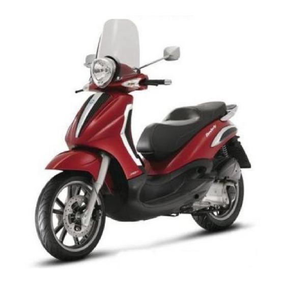
User Manuals: PIAGGIO Beverly 300 i.e. 300cc Scooter
Manuals and User Guides for PIAGGIO Beverly 300 i.e. 300cc Scooter. We have
4
PIAGGIO Beverly 300 i.e. 300cc Scooter manuals available for free PDF download: Service Station Manual, User Manual
PIAGGIO Beverly 300 i.e. Service Station Manual (339 pages)
Brand:
PIAGGIO
| Category:
Scooter
| Size: 47 MB
Table of Contents
Index of Topics
5
Characteristics
6
Safety Rules
7
Maintenance Rules
7
Vehicle Identification
8
Dimensions and Mass
8
Chassis Number
8
Engine Number
8
Weights and Dimensions
9
Engine Data
9
Transmission Data
9
Capacities
9
Electrical System Data
10
Frame and Suspensions Data
10
Brakes Data
10
Wheels and Tyres Data
10
Front Brake Data
11
Rear Brake Data
11
Muffler Data
11
Lubrication Data
11
Overhaul Data
12
Assembly Clearances
12
Flywheel Data
12
Crankcase and Crankshaft Data
12
Cylinder - Piston Assy Assembly Clearances
13
Crankcase - Crankshaft - Connecting Rod Assembly Clearances
15
Crankshaft View
16
Max Admissible Displacement
17
Crankshaft-Crankcase Axial Clearance (H)
18
Bushings
18
Couplings
19
Crankshaft Category Identification
19
Cylinder Head
20
Slot Packing System
26
Engine 300 Shimming
27
Recommended Products Table
27
Units of Measure Conversion
27
Tooling
28
Specific Tools
29
Maintenance
39
Reset Service Warning Light
40
Maintenance Chart
40
Spark Plug
41
Hub Oil Check
41
Hub Oil Replacement
42
Air Filter
42
Engine Oil Replacement
43
Engine Oil Check
45
Engine Oil Filter
45
Oil Pressure Warning Light
46
Cooling System: Level Check
46
Braking System: Level Check
47
Top-Up
48
Headlight Adjustment
50
Troubleshooting
51
Engine Poor Performance
52
Starting Difficulties
52
Excessive Oil Consumption/Exhaust Smoke
52
Insufficient Lubrication Pressure
53
Clutch Grabbing or Performing Inadequately
53
Insufficient Braking
53
Brakes Overheating
53
Heavy Steering
54
Excessive Steering Play
54
Noisy Suspension
54
Suspension Oil Leakage
54
Electrical System
55
Electrical Components Arrangement
56
Instrument Panel
59
Ground Points
60
Electrical System Installation
60
Electrical Components View: Front Side
61
Electrical Components View: Back Side
64
Conceptual Diagrams
67
Ignition Diagram
70
Battery Recharge and Starting Diagram
71
Level Indicators and Enable Signals Section Diagram
72
Devices and Accessories Diagram
73
Lights and Turn Indicators Diagram
74
Checks and Inspections of the Electrical Components
75
Immobiliser Check
75
Virgin Circuit Check
78
Diagnostic Codes of the Immobilizer Sistem
78
Diagnostic Code - 1 Flash
79
Diagnostic Code - 2 Flashes
80
Diagnostic Code - 3 Flashes
80
Ignition Circuit
80
No Spark Plug
80
HV Coil Secondary Resistance Value
81
Battery Recharge Circuit
81
Remote Controls Check
81
Switches Check
82
Engine Stop Switch Check
82
Starter Button Check
82
Light Switch Check
82
Turn Indicator Switch
83
Horn Button
83
Helmet Compartment Light Switch
83
Saddle Opening Switch
83
Stator Check
84
Mode Button Check
84
Stand Button Check
84
Stop Buttons Check
84
Voltage Regulator Check
85
Recharge System Voltage Check
85
Starter Motor Schematic Diagram
86
Horn Control
87
Turn Signals System Check
88
Level Indicators
89
Lights List
89
Fuses
90
Dashboard
92
Sealed Battery
92
Battery Installation
93
Battery Preparation
93
Electrolyte Preparation
94
Procedure for Filling the Battery with Acid
94
Control the Flow of Electrolyte
94
Battery Closing
94
Recharging the New Battery
95
Connectors
97
Instrument Panel Connector a
97
Instrument Panel Connector B
97
Fuel Pump Connector
97
Electric Fan Connector
98
Pickup Connector
98
Antitheft Device Pre-Installation
98
Voltage Regulator Connector
98
Injection Electronic Control Unit Connector
99
Injector Connector
99
HV Coil Connector
100
Fuel Level Transmitter Connector
100
Coolant Temperature Sensor Connector
100
Engine from Vehicle
101
Exhaust Assy. Removal
102
Removal of the Engine from the Vehicle
103
Engine
108
Automatic Transmission
109
Transmission Cover
109
Air Duct
109
Removing the Driven Pulley Shaft Bearing
110
Refitting the Driven Pulley Shaft Bearing
110
Removing the Driven Pulley
111
Inspecting the Clutch Drum
111
Removing the Clutch
112
Inspecting the Clutch
113
Pin Retaining Collar
113
Removing the Driven Half-Pulley Bearing
114
Inspecting the Driven Fixed Half-Pulley
114
Inspecting the Driven Sliding Half-Pulley
115
Refitting the Driven Half-Pulley Bearing
116
Refitting the Driven Pulley
116
Inspecting the Clutch Spring
117
Refitting the Clutch
117
To Refit the Driven Pulley
119
Drive-Belt
119
Removing the Driving Pulley
119
Inspecting the Rollers Case
121
Refitting the Driving Pulley
122
Refitting the Transmission Cover
123
End Gear
123
Removing the Hub Cover
124
Removing the Wheel Axle
124
Removing the Hub Bearings
125
Removing the Wheel Axle Bearings
125
To Remove the Driven Pulley Shaft Bearing
126
Inspecting the Hub Shaft
126
Inspecting the Hub Cover
127
Refitting the Wheel Axle Bearing
128
Refitting the Hub Cover Bearings
129
Refitting the Hub Bearings
130
Refitting the Hub Cover
130
Flywheel Cover
130
To Remove the Hub Cover
131
Removing the Stator
132
Refitting the Stator
132
Refitting the Flywheel Cover
132
Flywheel and Starting
133
Removing the Starter Motor
134
Removing the Flywheel Magneto
134
Inspecting the Flywheel Components
135
Starter Gear Rim
135
Intermediate Gear
136
Refitting the Free Wheel
136
Refitting the Flywheel Magneto
137
Refitting the Starter Motor
137
Cylinder Assy. and Timing System
138
Removing the Intake Manifold
138
Removing the Rocker-Arms Cover
138
Removing the Timing System Drive
138
Removing the Cam Shaft
139
Removing the Cylinder Head
140
Removing the Valves
141
Removing the Cylinder - Piston Assy.
142
Inspecting the Small End
142
Inspecting the Wrist Pin
142
Inspecting the Piston
143
Inspecting the Piston Rings
143
Removing the Piston
143
Choosing the Gasket
144
Refitting the Piston Rings
145
Refitting the Cylinder
145
Inspecting the Cylinder Head
146
Inspecting the Timing System Components
146
Inspecting the Valve Sealings
147
Inspecting the Valves
147
Inspecting the Springs and Half-Cones
147
Refitting the Valves
148
Inspecting the Cam Shaft
148
Refitting the Head and Timing System Components
148
Refitting the Rocker-Arms Cover
151
Refitting the Intake Manifold
151
Crankcase - Crankshaft
151
Splitting the Crankcase Halves
151
Inspecting the Crankshaft Components
153
Inspecting the Crankshaft Alignment
153
Inspecting the Crankcase Halves
154
Inspecting the Crankshaft Plain Bearings
155
Coupling Chart
155
Refitting the Crankcase Halves
156
Studs
157
Lubrication Conceptual Diagrams
158
Oil Pressure Check
159
Crankshaft Oil Seals
159
Crankshaft Oil Seals Removal
160
Crankshaft Oil Seals Refitting
160
Oil Pump
161
Oil Pump Removal
162
Oil Pump Inspection
162
Oil Pump Refitting
163
Removing the Oil Sump
164
Inspecting the By-Pass Valve
165
Refitting the Oil Sump
165
Injection
166
MIU Injection System
167
Precautions (MIU)
169
Terminals Setup
171
EMS Circuit Diagram
172
Injection: Troubleshooting Procedure
173
Engine Does Not Start
173
System Diagram
173
Engine Stops at Idle
174
Engine Does Not Rev down
174
Exhaust Backfires in Deceleration
175
Engine Revs Irregularly
175
Poor Performance at Full Throttle
176
Engine Knocking
176
Fuel Supply System
176
Removing the Butterfly Valve
177
Refitting the Butterfly Valve
179
Pump Supply Circuit
180
Circuit Leak Test
183
Fuel Filter Check
184
Inspecting the Injector Circuit
185
Inspecting the Injector Hydraulics
189
Components Location
190
Tachometer
191
HT Coil
192
Coolant Temperature Sensor
196
Zeroing the Throttle
197
Lambda Probe
199
Suspensions
201
Front Suspension
202
Removing the Front Wheel
202
Front Wheel Hub Overhaul
202
Refitting the Front Wheel
205
Handlebar Removal
205
Handlebar Refitting
206
Front Fork Removal and Ovehaul
206
Front Fork Refitting
210
Steering Column Removal
213
Steering Column Refitting
214
Steering Bearing Removal
217
Steeringh Fifth Wheel Track Removal
218
Steeringh Fifth Wheel Track Refitting
219
Rear Suspension
220
Removing the Rear Wheel
220
Refitting the Rear Wheel
220
Swingarm
220
Swingarm Removal
221
Swingarm Overhaul
221
Swinging Arm Service
224
Swinging Arm Refitting
225
Swinging Arm Fittings
226
Shock Absorbers
226
Shock Absorbers Removal
227
Shock Absorbers Refitting
227
Exhaust Bracket Removal
227
Exhaust Bracket Overhaul
230
Exhaust Bracket Refitting
230
Centre-Stand
231
Side Stand
231
Braking System
232
Braking System: Interventions Rules
233
Rear Brake Caliper
233
Rear Brake Caliper Removal
234
Rear Brake Caliper Refitting
234
Front Brake Caliper
234
Front Brake Caliper Removal
235
Front Brake Caliper Refitting
235
Rear Brake Disc Removal
235
Rear Brake Disc Refitting
236
Disc Inspection
237
Front Brake Disc Removal
237
Front Brake Disc Refitting
237
Front Brake Pads
238
Front Brake Pads Removal
239
Front Brake Pads Refitting
239
Rear Brake Pads Removal
240
Rear Brake Pads Refitting
241
Fill - Rear Combined
241
Fill - Front
242
Brake Fluid Level Check
242
Front Brake Pump Removal
243
Front Brake Pump Refitting
243
Rear Brake Pump - Combined
243
Rear Brake Pump - Combined, Removal
244
Rear Brake Pump - Combined, Refitting
244
Cooling System
245
Cooling System Circuit Diagram
246
Cooling System Specifications
247
Electric Fan Check
247
Cooling System Bleed
248
Thermostat Removal
249
Thermostat Check
250
Thermostat Refitting
250
Chassis
251
Seat
252
Rear Rack
252
Rear Handlebar Cover
253
Front Handlebar Cover
255
Headlight Assy.
255
Frame Central Cover
255
Legshield
256
Knee-Guard
258
Removing the Ignition Key-Switch When on off
260
Removing the Ignition Key-Switch When on *Lock*
261
Front Wheel Housing
261
Taillight Assy.
262
Footrest
262
Side Fairings
263
License Plate Holder
265
Helmet Bay
265
Fuel Tank Diagram
267
Fuel Tank Removal
268
Front Mudguard
276
Radiator Fan
277
Expansion Tank
277
Battery
278
Pre-Delivery
279
Aesthetic Inspection
280
Tightening Torques Inspection
280
Electrical System Inspection
280
Levels Check
281
Road Test
281
Test Ride
281
Static Test
282
Functional Inspection
282
Instruments Start-Up
282
Trip Counter Partial Reset
283
Select Miles - Km
283
Time
284
Engine Diagram
285
Crankcase Diagram
286
Crankshaft Diagram
287
Cylinder Assy Diagram
288
Cylinder Head Assy Diagram
289
Rocker Arms Support Assy Diagram
290
Cylinder Head Cover Diagram
291
Oil Filter Diagram
292
Flywheel Cover Diagram
293
Driven Pulley Diagram
294
Oil Pump Diagram
295
Final Gear Assy Diagram
296
Final Reduction
296
Driving Pulley Diagram
297
Transmission Cover Diagram
298
Water Pump Diagram
299
Starter Motor Diagram
300
Flywheel Magneto Diagram
301
Butterfly Valve Diagram
302
Exhaust Pipe Diagram
303
Air Cleaner Diagram
304
Frame Diagram
305
Centre-Stand Diagram
306
Legshield Spoiler Diagram
307
Side Fairings Diagram
308
Rear Cover Diagram
309
Central Cover Diagram
310
Underseat Compartment
311
Plate Holder Diagram
312
Mudguard Diagram
313
Fuel Tank Exploded View
314
Rear Shock-Absorber Diagram
315
Handlebar Covers Diagram
316
Handlebar Components Diagram
317
Swing-Arm Diagram
318
Brake Hoses Diagram
319
Seat Diagram
320
Instrument Panel Diagram
321
Rear Rack Diagram
322
Locks Diagram
323
Turn Signal Lights Diagram
324
Front Wheel Diagram
325
Rear Wheel Diagram
326
Fuel Pump Diagram
327
Electric Devices Diagrams
328
Voltage Regulator Diagram
328
Remote Controls Diagram
329
Cable Assembly Diagram
330
Electronic Controls Diagram
331
Transmissions Diagram
332
Front Suspension Diagram
333
Cooling System Diagram
334
Windscreen Diagram
335
Stickers Diagram
336
Index
337
Advertisement
PIAGGIO Beverly 300 i.e. Service Station Manual (334 pages)
Brand:
PIAGGIO
| Category:
Scooter
| Size: 18 MB
Table of Contents
Index of Topics
5
Safety Rules
7
Maintenance Rules
7
Vehicle Identification
8
Dimensions and Mass
9
Weights and Dimensions
9
Wheels and Tyres
10
Crankcase and Crankshaft
13
Cylinder Head
21
Index of Topics
29
Specific Tools
30
Maintenance
40
Maintenance Chart
41
Checking the Spark Advance
41
Spark Plug
43
Air Filter
45
Engine Oil
46
Engine Oil Filter
47
Oil Pressure Warning Light
48
Checking the Ignition Timing
48
Cooling System
48
Level Check
49
Braking System
50
Headlight Adjustment
51
Index of Topics
53
Troubleshooting
53
Poor Performance
54
Difficult Starting
54
Noisy Suspension
56
Electrical System
57
Electrical System Installation
71
Front Side
72
Back Side
75
Devices and Accessories
81
Checks and Inspections
83
Diagnostic Codes
86
Ignition Circuit
88
Engine Stop Switch
89
Stator Check
91
Voltage Regulator/Rectifier
93
Starter Motor
93
Horn Control
94
Battery Installation
100
Index of Topics
108
Automatic Transmission
116
Removing the Driven Pulley Shaft Bearing
117
Removing the Driven Pulley
118
Inspecting the Clutch Drum
119
Removing the Clutch
120
Refitting the Driven Pulley
124
Removing the Driving Pulley
127
Removing the Stator
137
Removing the Starter Motor
139
Removing the Intake Manifold
142
Removing the Cam Shaft
145
Removing the Cylinder Head
145
Removing the Valves
146
Removing the Piston
148
Inspecting the Cylinder Head
150
Inspecting the Cam Shaft
152
Crankcase - Crankshaft
156
Lubrication Circuit
161
Oil Pressure Check
163
Crankshaft Oil Seals
163
Index of Topics
170
Component Layout
171
Terminal Layout
176
System Diagram
177
Troubleshooting Procedure
177
Electrical Data
185
Components Location
195
Coolant Temperature Sensor
202
Lambda Probe
206
Signal Control
209
Index of Topics
210
Removing the Front Wheel
211
Front Wheel Hub Overhaul
211
Refitting the Front Wheel
214
Component Check
218
Steering Column
222
Steering Bearing
226
Removing the Rear Wheel
230
Refitting the Rear Wheel
230
Shock Absorbers
236
Centre-Stand
239
Side Stand
239
Index of Topics
240
Rear Brake Calliper
241
Disc Inspection
245
Front Brake Pads
247
Rear Brake Pads
248
Index of Topics
254
Circuit Diagram
255
Rear Mudguard
270
Front Mudguard
273
Radiator Fan
273
Static Test
278
Functional Inspection
278
Cylinder Assy
283
Cylinder Head Assy
284
Cylinder Head Cover
286
Oil Filter
287
Flywheel Cover
288
Driven Pulley
289
Oil Pump
290
Driving Pulley
292
Transmission Cover
293
Water Pump
294
Electrical Start-Up
295
Flywheel Magneto
296
Butterfly Valve
297
Throttle Body
297
Exhaust Pipe
298
Air Cleaner
299
Side Covers
303
Rear Cover
304
Rear Shield
304
Underseat Compartment
306
Helmet Compartment
306
Rear Shock Absorber
310
Handlebar Covers
311
Handlebar Components
312
Swinging Arm
313
Brake Hoses
314
Instrument Panel
316
Luggage Rack
317
Turn Signal Lights
319
Indicator Lights
319
Front Wheel
320
Rear Wheel
321
Fuel Pump
322
Electric Devices
323
Voltage Regulator
323
Electronic Controls
326
Electric Controls
326
PIAGGIO Beverly 300 i.e. User Manual (90 pages)
Brand:
PIAGGIO
| Category:
Scooter
| Size: 1 MB
Table of Contents
Table of Contents
5
Vehicle
7
Dashboard
9
Analogue Instrument Panel
9
Clock
12
Key Switch
12
Locking the Steering Wheel
13
Releasing the Steering Wheel
13
Switch Direction Indicators
14
Horn Button
14
Light Switch
15
Start-Up Button
15
Engine Stop Button
16
The Immobilizer System
16
Keys
16
Immobilizerdevice Enabled Indicator Led
17
Operation
18
Programming the Immobilizer System
19
Accessing the Fuel Tank
20
Power Supply Socket
21
Opening the Saddle
22
Identification
22
Rear Top Box Opening
24
Bag Clip
24
Use
25
Checks
26
Refuelling
26
Tyre Pressure
28
Shock Absorbers Adjustment
29
Running in
30
Starting up the Engine
31
Stopping the Engine
32
Anti-Theft Ring
32
Stand
32
Automatic Transmission
34
Safe Driving
34
Maintenance
37
Engine Oil Level
38
Engine Oil Level Check
38
Engine Oil Top-Up
39
Warning Light (Insufficient Oil Pressure) (03_03
39
Engine Oil Change
40
Hub Oil Level
41
Tyres
43
Spark Plug Dismantlement
45
Removing the Air Filter
46
Air Filter Cleaning
47
Cooling Fluid Level
47
Checking the Brake Oil Level
49
Braking System Fluid Top up
49
Battery
50
Use of a New Battery
51
Long Periods of Inactivity
52
Fuses
52
Lamps
56
Front Light Group
58
Headlight Adjustment
60
Front Direction Indicators
61
Rear Optical Unit
61
Number Plate Light
63
Helmet Compartment Lighting Bulb
64
Rear-View Mirrors
64
Front and Rear Disc Brake
64
Puncture
65
Periods of Inactivity
66
Cleaning the Vehicle
67
Troubleshooting
68
Technical Data
73
Kit Equipment
78
Spare Parts and Accessories
79
Warnings
80
Programmed Maintenance
83
Scheduled Maintenance Table
84
Advertisement
PIAGGIO Beverly 300 i.e. User Manual (88 pages)
278 cc single-cylinder engine
Brand:
PIAGGIO
| Category:
Scooter
| Size: 1 MB
Table of Contents
Table of Contents
5
Vehicle
7
Dashboard
9
Analogue Instrument Panel
10
Digital Lcd Display
11
MODE* Button
12
Key Switch
12
Locking the Steering Wheel
13
Releasing the Steering Wheel
13
Switch Direction Indicators
14
Horn Button
14
Light Switch
15
Start-Up Button
15
Engine Stop Button
16
The Immobilizer System
16
Keys
16
Immobilizerdevice Enabled Indicator Led
17
Operation
18
Programming the Immobilizer System
19
Accessing the Fuel Tank
20
Power Supply Socket
21
Opening the Saddle
21
Identification
22
Rear Top Box Opening
23
Bag Clip
24
Use
25
Checks
26
Refuelling
26
Tyre Pressure
28
Shock Absorbers Adjustment
29
Running in
30
Starting up the Engine
31
Precautions
32
Difficult Start up
32
Stopping the Engine
33
Stand
33
Automatic Transmission
34
Safe Driving
35
Maintenance
39
Engine Oil Level
40
Engine Oil Level Check
40
Engine Oil Top-Up
41
Warning Light (Insufficient Oil Pressure) (03_04
41
Engine Oil Change
42
Hub Oil Level
43
Tyres
45
Spark Plug Dismantlement
47
Removing the Air Filter
48
Air Filter Cleaning
48
Cooling Fluid Level
49
Checking the Brake Oil Level
51
Braking System Fluid Top up
51
Battery
54
Use of a New Battery
55
Long Periods of Inactivity
55
Fuses
56
Lamps
59
Front Light Group
60
Headlight Adjustment
62
Front Direction Indicators
63
Rear Optical Unit
64
Number Plate Light
65
Helmet Compartment Lighting Bulb
65
Rear-View Mirrors
65
Front and Rear Disc Brake
66
Puncture
67
Periods of Inactivity
68
Cleaning the Vehicle
68
Troubleshooting
70
Technical Data
73
Toolkit
78
Spare Parts and Accessories
79
Warnings
80
Scheduled Maintenance
83
Scheduled Servicing Table
84
Advertisement
Related Products
PIAGGIO LUM Beverly Sport Touring 350 ie
Piaggio Beverly 250 USA
PIAGGIO Beverly 500 i.e.
PIAGGIO Beverly 400 I.E
PIAGGIO Beverly Tourer 125
PIAGGIO Beverly Tourer 250 i.e.
PIAGGIO Beverly Tourer 250ie 2007
PIAGGIO beverly 500
PIAGGIO Beverly 400 E5
PIAGGIO 1962 Vespa 150
PIAGGIO Categories
Scooter
Motorcycle
Motorcycle Accessories
Utility Vehicle
Automobile
More PIAGGIO Manuals
Login
Sign In
OR
Sign in with Facebook
Sign in with Google
Upload manual
Upload from disk
Upload from URL