Sign In
Upload
Manuals
Brands
Moog Manuals
Water Pump
RKP-D
Moog RKP-D Manuals
Manuals and User Guides for Moog RKP-D. We have
1
Moog RKP-D manual available for free PDF download: User Manual
Moog RKP-D User Manual (178 pages)
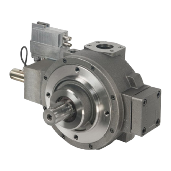
RADIAL PISTON PUMP
Brand:
Moog
| Category:
Water Pump
| Size: 6 MB
Table of Contents
Table of Contents
3
List of Tables
7
General Information
11
About this Manual
11
Reservation of Changes and Validity
11
Completeness
11
Place of Storage
11
Warranty and Liability
11
Typographical Conventions
12
Selection and Qualification of Personnel
12
Further Documentation for the Device
12
References
13
Definitions
13
Representation of Parameters
14
Representation of Parameters in the Object Dictionary
14
Table 1: Representation of Objects
14
Table 2: Meaning of Object Entries
14
Table 3: Meaning of Entries in Object Dictionary
14
Definition of Unit and Prefix
15
Unit Representation
15
Prefix Representation
15
Abbreviations
15
Table 4: Code Table for Units
15
Table 5: Code Table for Prefixes
15
Table 6: Abbreviations
15
Access over Canopen
19
Introduction
19
Table 7: Object Dictionary Structure
19
Figure 1: Device Model
19
Communication Profile Area
20
Table 8: Object Entries in the Communication Profile Area
20
Service Data Objects (Sdos)
21
Process Data Objects (Pdos)
21
Object 0X3012: Receive PDO Counter
21
Table 9: Service Data Objects (Sdos)
21
Table 10: Process Data Objects (Pdos)
21
Synchronization Object (SYNC)
22
Object 0X3013: Synchronization Timer
22
Emergency Object (EMCY)
22
Network Management (NMT)
22
Table 11: Synchronization Object (SYNC)
22
Table 12: Emergency Object (EMCY)
22
Table 13: Network Management Object (NMT)
22
Node Guarding
23
Table 14: Node Guarding Object
23
The Device Layer Setting Services (LSS)
24
Figure 2: Name Plate of a Valve
24
Device Structure
25
Figure 3: the Device's Logical Structure
25
Figure 14: Demand Value Generator
25
Device Identification
27
Object Descriptions
27
Object 0X1000: Device Type
27
Table 15: <Devicetype> Values
27
Object 0X1018: Identity
28
Object 0X1008: Manufacturer Device Name
28
Object 0X1009: Manufacturer Hardware Version
28
Object 0X100A: Manufacturer Software Version
28
Table 16: Identity Object Values
28
Object 0X6050: Device Version
29
Object 0X6051: Code Number
29
Object 0X6052: Serial Number
29
Object 0X6053: Description
29
Object 0X6054: Model Description
29
Object 0X6055: Model URL
29
Object 0X6056: Parameter Set Code
30
Object 0X6057: Vendor Name
30
Table 17: Value Definition of the Parameter Set Identification
30
Object 0X605F: Capability
31
Table 18: <Capability> Data Structure
31
Table 19: Device Capability Values
31
Device Control
33
Structure
33
Figure 4: Device Control Block
33
State Machine
34
Figure 5: Device State Machine
34
Device States
35
State Transitions
36
State Transitions Depending on the Control Word
36
State Transitions through Internal Events
36
Table 20: Device Control Commands
36
Table 21: Status Transitions through Internal Events
36
Object Descriptions
37
Object 0X6040: Control Word
37
Table 22: Control Word Value Definition
37
Object 0X4040: Local Control Word
38
Object 0X403F: Local Control Word Default
38
Object 0X604F: Local
38
Table 23: <Local> Values
38
Object 0X6041: Status Word
39
Table 24: Status Word Values
39
Bootup of the Device
40
Status Display Leds
41
Table 25: Network Status LED "NS
41
Table 26: Module Status LED "MS
41
Signal Routing and Scaling
43
Figure 6: Signal Routing
43
Physical Pump Interfaces
44
Analog Inputs 0 and 1
44
Table 27: Physical Pump Interfaces
44
Table 28: <Inputtype> Values Analog Input 0
44
Table 29: <Inputtype> Values Analog Input 1
45
Analog Inputs 2, 3 and 4
46
Table 30: <Inputtype> Values Analog Input 2
46
Table 31: <Inputtype> Values Analog Input 3
47
Table 32: <Inputtype> Values Analog Input 4
47
Analog Outputs
48
Table 33: Scaling Parameters of Analog Outputs
48
Figure 7: Access to Parameter Value Via Analog Output
48
Figure 8: Analog Output Scaling
48
Command Value Path
49
Figure 9: Command Value Paths Position and Pressure
50
Object Descriptions
51
Table 34: Definition of the Position Setpoint Source
52
Table 35: Definition of the Pressure Setpoint Source
53
Table 36: Device Mode Values
55
Actual Value Path
56
Position Actual Value Path
56
Figure 10: Position Actual Value Path
56
Pressure Actual Value Path
57
Figure 11: Pressure Actual Value Path
57
Interface Assignment
58
Figure 12: Actual Value Conditioning
58
Interface Definition
59
Table 37: Interface Parameters
59
Table 38: <Interfaceno> Values
59
Table 39: Interface Types
60
Table 40: Interface Sign Values
60
Table 41: Analog Inputs with Value Parameters
61
Table 42: Bit Coding of the Transducer Port Value
61
Object 0X230D: Pressure Controller Active Transducer Interface
62
Objects 0X6120 - 0X6125: Actual Value Conditioning for Pressure Transducer
63
Figure 13: Scaling and Offset of the Pressure Value
63
Pump Functions
65
Demand Value Generator
65
Structure
65
Position Demand Value Generator
65
Figure 15: Position Demand Value Generator
66
Limit Function
67
Table 43: Definition of the Limit Value Status
67
Figure 16: Limit Function
67
Scaling
68
Table 44: Data Structure of the Scaling Factor
68
Figure 17: Scaling Function
68
Ramp
69
Table 45: Possible Ramp Type Values
69
Figure 18: Ramp Function
69
Table 46: Ramp Status Indicated in the Status Word
70
Figure 19: Ramp Type 1
70
Figure 20: Ramp Type 2
71
Figure 21: Ramp Type 3
72
Zero Correction
74
Figure 22: Zero Correction
74
Hybrid Mode Correction
75
Figure 23: Transfer Behavior Hybrid Mode / solo Mode
75
Pressure Demand Value Generator
76
Figure 24: Pressure Demand Value Generator
76
Limit Function
78
Table 47: Definition of the Limit Value Status
78
Figure 25: Limit Function
78
Scaling
79
Table 48: Data Structure of the Scaling Factor
79
Figure 26: Scaling Function
79
Ramp
80
Table 49: Possible Ramp Type Values
80
Figure 27: Ramp Function
80
Table 50: Ramp Status Indicated in the Status Word
81
Figure 28: Ramp Type 1
81
Figure 29: Ramp Type 2
82
Figure 30: Ramp Type 3
83
Controller
85
Control Modes
85
Table 51: Control Mode Values
86
Monitoring
87
Table 52: Control Deviation Indicated in Status Word
87
Figure 32: Monitoring the Control Deviation's Tolerance Band
87
Stroke Ring Control Monitoring
88
Table 53: Control Monitoring Types
88
Figure 31: Deviation Monitoring
88
Pressure Control Monitoring
89
Table 54: Control Monitoring Types
89
Control Position Open Loop
90
Figure 33: Control Position Open Loop
90
Control Position Closed Loop
91
Figure 34: Control Position Closed Loop
91
Leakage Compensation
92
Figure 35: Leakage Compensation
92
Pressure Control Open Loop
93
Figure 36: Pressure Control Open Loop
94
Pressure Control Closed Loop
95
Figure 37: Pressure Control Closed Loop
96
Controller Structure
97
Figure 38: Pressure Controller Structure
98
Controller Parameters
99
Object 0X2350: Active Parameter Set Number
102
Table 55: Pressure Controller Parameter Set
102
P/Q Closed Loop
103
Controller Structure
104
Figure 39: P/Q Controller
104
Power Limitation
105
Figure 40: Power Limitation Structure
105
Master/Slave Operation
108
Figure 41: RKP-D Control Structure with Slave Pump
109
Table 56: Master Slave Selection
110
Local Holding Pressure Switchover
112
Table 57: Control Word Bit 13 Values
112
Figure 42: Hold Pressure Setpoint Behavior
112
Table 58: Control Word and Status Word Bits for Local Holding Pressure Switchover
113
Table 59: Control Word Bits
113
Table 60: Status Word Bits
113
Figure 43: Status Machine of the Hold Pressure Enable
113
Flushing Mode
114
Analog Parameter Set Switching
115
Table 61: Relation between Value of <Activeparameterset> and Interface Input Range
115
Figure 44: Assignment of Analog Input Value to Active Parameter Set
115
Figure 45: Assignment of <Pressuresetselector> Subindex to Active Parameter Set Number
116
Objects 0X2141 - 0X2146 / 0X2148: Active Parameter Set
117
Diagnostics
119
Error Information
119
Object 0X1001: Error Register
119
Table 62: Bit Coding of Error Register Value
119
Object 0X1003: Predefined Error Field
120
Objects 0X2832/0X2833: Fault Reaction Description / Fault History Number
121
Objects 0X2822/0X2823 Error Handler: Address / Time
121
Fault Reaction
122
Fault Reaction Settings
122
Table 63: Type Subindex Values
122
Table 64: Fault Reaction Settings
125
Figure 46: Fault Reaction Behavior
126
Emergency Message
127
Table 65: Error Codes
128
Object 0X2831: Fault Reaction Status
131
Table 66: Fault Reaction Status Bits
132
Fault Acknowledgement
135
Monitoring Features
136
Object 0X2803: CPU Supply Voltage
136
Object 0X2804: Power Supply Voltage
136
Table 67: Fault Reactions for CPU Supply Voltage Failure
136
Table 68: Fault Reactions for Power Supply Voltage Failure
136
Object 0X2805: PCB Temperature
137
Object 0X280D: Operating Time
137
Table 69: Fault Reactions for PCB Temperature Failure
137
Cable Break Monitoring
138
Table 70: Monitoring Description for Analog Input Types
138
Table 71: Cable Break Monitoring (Assignment Input to Fault Code)
139
Storing / Restoring Parameters
141
Storing Parameters
141
Table 72: Behavior of Savable and Volatile Parameters
141
Table 73: Parameter Groups (Store Command)
141
Object 0X1010: Store Parameters
142
Restoring Default Parameters
143
Table 74: Parameter Groups (Restore Command)
143
Object 0X1011: Restore Default Parameters
144
Object Dictionary
145
Table 75: Object Dictionary
145
Advertisement
Advertisement
Related Products
Moog RKP-II
Moog RKP
Moog RHW75C12N
Moog RHW75 SERIES
Moog RM7C2N
Moog The Rogue
Moog RHP75C2N
Moog R360-IV
Moog RM7CF2
Moog RM7TF2N
Moog Categories
Synthesizer
Control Unit
Servo Drives
Medical Equipment
Security Camera
More Moog Manuals
Login
Sign In
OR
Sign in with Facebook
Sign in with Google
Upload manual
Upload from disk
Upload from URL