Sign In
Upload
Manuals
Brands
GE Medical Systems Manuals
Medical Equipment
LUN7396
GE Medical Systems LUN7396 Manuals
Manuals and User Guides for GE Medical Systems LUN7396. We have
1
GE Medical Systems LUN7396 manual available for free PDF download: Service Manual
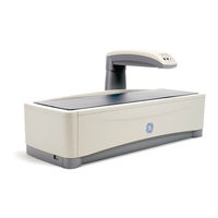
GE Medical Systems LUN7396 Service Manual (179 pages)
Brand:
GE Medical Systems
| Category:
Medical Equipment
| Size: 42.65 MB
Table of Contents
1 1 1 1 2 Safety
7
Table of Contents
7
General Safety
9
Symbols and Labels Found on the PRODIGY
9
External Symbols
9
Internal Symbols
10
Labels
10
Emergency Stop Button
13
Laser Exposure
14
Shutter Indicator
15
Cautions, Warnings, and Notes
15
Caution Statements
15
Pinch Points
16
Note Statements
16
Safety Concerns
16
Warning Statements
16
Laser Safety
17
Radiation Safety
18
Scatter Radiation
18
Figure 1-8. PRODIGY Iso-Dose Diagram
19
Controlling Computer and Accessories
20
Electrical Safety
20
Peripheral Configurations
20
Small Room Configuration (System No. DF+12000 and Higher)
21
Scanner Power Output Configuration
21
Wall Outlet Configuration (System No. DF+11999 and Lower)
21
2 1 1 1 2 System Overview
23
PRODIGY Electronics
27
PRODIGY System
27
Cautions
29
Electronics
29
Electronics Pan
29
Power Specifications
30
Scan Arm
30
PRODIGY Block Diagrams
32
PRODIGY I (System Numbers DF+11999 and Lower) Power Distribution Block Diagram (AC Entrance)
32
Diagram
33
PRODIGY System Block Diagram PRODIGY I System Block
33
PRODIGY I Peripheral Configuration Block Diagrams
34
PRODIGY II System / Power Block Diagram
35
PRODIGY Fusing
36
Controller
37
PRODIGY I (System Numbers DF+11999 and Lower) Single Board
37
SBC Functions
37
SBC Reset
37
SBC / Host PC Interface
38
Csbc System Architecture
39
PRODIGY II Combined Single Board Controller (Csbc) (Systems DF+12000 and Greater)
39
Csbc Functions
40
TRANS / LONG MOTOR Control and Status
44
Ags Dac
45
Ags Roll
45
Scanner Reset
46
GE-LUNAR Model 7861 X-Ray Generator Errors
47
DC Fail
48
DCA / AGS / BIAS Dac's
48
Arc/Fil Dac
49
Kv/Ma DAC
49
MAX PLD Peripherals
49
Peak Dac
49
Interrupts
50
Master Reset
50
Misc out
51
Suicide Reset
51
Misc in
52
Stepper Motor Control
52
Limit Switches
53
OMI Input
53
Patient Positioners
53
X-Ray Source Control / Mechanical Interlocks
53
End of Exposure Alarm
54
HVPS Control
54
Panel Led's
54
Shutter / Collimator Drive
54
Adc
55
Detector Interface
55
Ma Low Range
55
Communications Ports
56
Debug RS-232 Port
56
Diagnostic Led's
56
Power Distribution (PRODIGY II Systems DF+1200 and Greater)
58
Tube Head and X-Ray Insert
59
X-Ray Generation and Spectrum
59
X-Ray Generator (High Voltage Power Supply(Ies))
60
Dedicated +28VDC Power Supply
61
MAX Board (PRODIGY I Systems DF+11999 and Lower Only)
61
MAX Board Function
61
XORB Board (PRODIGY I Systems DF+11999 and Lower Only)
62
Detector Operation
63
Detector Overview
63
Detector Sub System
63
Detector Daughter Board Overview
64
Detector Daughter Board Operation
65
Detector Mother Board Operation
66
Detector Mother Board Overview
66
FOINK (PRODIGY I Systems DF+11999 and Lower Only)
68
FOINK Functions
68
Motion Control and Detection
68
Display Panel
69
Audible X-RAY off Signal
71
X-Ray Collimator Subsystem
72
Component Specifications
73
Functional Specifications
73
Maximum Scan Area (Long X Transverse)
73
PRODIGY Specifications
73
Environmental Specifications
74
Programs
74
Storage and Transport Environment
75
X-Ray Generator (System No. DF+12000 and Higher)
75
X-Ray Generator (System No. DF+11999 and Lower)
77
GE-LUNAR 8022 X-Ray Tube
79
DF+12000 and Higher)
80
GE-LUNAR 8743 X-Ray Tube Head Assembly
80
DF+11999 and Lower)
81
LUNAR 6838 X-Ray Tube Head Assembly
81
Laser Specifications
82
Compatible Components
83
FDA Certified Components (USA Only)
83
Secondary Calibration / Daily QA
85
Secondary Calibration Overview
85
Starting the Daily QA (Secondary Calibration)
85
Peak Test
86
Tests Performed in the Secondary Calibration
86
3 1 1 1 Service Software
91
Diagnostic Software
93
To Access the Service Software
93
Pileup
94
Primary Calibration
94
Secondary Verification
94
Set Download Parameters
94
Signal Monitor
94
Spectrum
94
Stability Run
94
The Tools Menu
94
Copy Configuration
95
Encore Composer
95
Error Log
95
Outbox
95
Pileup
95
Service Options
95
Spillover
95
System File Editor
95
Tools / Diagnostics Menu
95
User Options
95
Scanner Detector
96
Scanner X-Ray
97
Alignment Scan
98
Beam Wobble Scan
98
Diagnostic Scan Modes
98
Hacksaw
98
Limit Switch Adjustment
98
Lin/Rep
98
Scanner Disconnect
98
4 1 1 1 2 Troubleshooting
103
Diagnostic Failure Codes
105
Mechanical Failures - Unusual Noise or Irregular Motion
105
Operator Induced - Switch Closed During Scan
105
Transverse Motion Failure
105
Loss of OMI Signal
107
Limit Switch Tripped During a Scan
108
Longitudinal Motion Failure
108
Longitudinal Binding
109
Loss of OMI Signal
111
Failure of the 28V Power Supply
112
Communication Error
113
Emergency Stop Button
113
Other Diagnostic Failure Codes
113
Tube Head Thermostat
113
Beam Stop Action
114
Block Position
114
Failing Quality Assurance Test
114
Mean% Spillover
114
Reasons for Invalid Diagnostic Failures
114
Ratio Fluctuations
115
Reference Counts and Ratio
115
Transverse or Longitudinal Mechanics
115
Bone Mineral of the Standard Chambers
116
Tissue Value
116
Reference Counts
117
Symptoms of High and Low KV
117
Arcing
120
Limit Switch Tripped During Scan
121
Femur Scan Problems
122
Imaging Problems
122
White, or Grey in the First or Second Scan Line
122
AP-Spine Image Problems: Probable Causes
123
Broken Signal Cable
123
Loss of Tube Head Current
123
X-Ray Relay Failure
123
Indicator Failures
126
Shutter Open LED Blinking
126
X-Ray on LED Blinking
126
End of Exposure Alarm During Scan
127
Shutter Not Operating
127
Communications Failures
128
Viewing Quality Assurance Trends
128
MAX Board Troubleshooting
129
What to Look for in the QA History
129
FOINK Board Troubleshooting
130
OMI Board Troubleshooting
131
SBC Troubleshooting
131
XORB Troubleshooting
133
Detector Motherboard Troubleshooting
134
Detector Daughter Board Troubleshooting
135
5 1 1 1 Service Procedures
139
Peaking Procedure
141
Peaking the Detector
141
Reloading LUNAR Software
141
Tube Head Replacement
142
Lower Cable Bundle Replacement
143
Mounting the Tube Head
143
Procedure
143
Shelf Life
143
Procedure
146
Upper Cable Bundle Replacement
146
Procedure
148
Tube Head Control Cable Replacement
148
Tests to Perform after Service
151
Returning Parts to LUNAR (for International Distributors)
152
Advertisement
Advertisement
Related Products
GE Medical Systems LOGIQ ?200
GE Medical Systems LOGIQ 7
GE Medical Systems LOGIQ 500
GE Medical Systems LOGIQ 7 Pro
GE Medical Systems LOGIQ 400
GE Medical Systems 500
GE Medical Systems Corometrics 340
GE Medical Systems Dash 3000
GE Medical Systems Dash 4000
GE Medical Systems MAC 1200
GE Medical Systems Categories
Medical Equipment
Treadmill
More GE Medical Systems Manuals
Login
Sign In
OR
Sign in with Facebook
Sign in with Google
Upload manual
Upload from disk
Upload from URL