Sign In
Upload
Manuals
Brands
Furuno Manuals
Marine Radio
FA-150
Furuno FA-150 Manuals
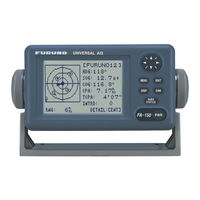
Manuals and User Guides for Furuno FA-150. We have
8
Furuno FA-150 manuals available for free PDF download: Installation Manual, Operator's Manual, Isntallation Manual
Furuno FA-150 Installation Manual (216 pages)
UAIS TRANSPONDER
Brand:
Furuno
| Category:
Marine Radio
| Size: 20 MB
Table of Contents
Table of Contents
15
System Configuration
16
Equipment Lists
17
1 Mounting
18
Antenna Units
18
GPS Antenna Unit
18
VHF Antenna
20
GPS/VHF Combined Antenna
22
Monitor Unit
25
UAIS Transponder
27
Power Supply (Option)
28
Pilot Plug (Option)
28
2 Wiring
29
Connection
29
Changing Ship's Mains Specifications
34
3 Setting and Adjustment
35
Setting MMSI IMO No., Name and Call Sign
35
Setting GPS Antenna Position
37
Setting Ship Type
38
Setting I/O Port
38
4 Attaching Lan Kit (Option)
42
Table of Contents
74
Cabin Buzzer
76
Buzzer Bedhead - 10 Tone
76
Hatteland Display
78
Hatteland Hd08T21Mmc
78
General
78
Maritime Multi Computer (MMC) - Introduction
78
Labels and Locations
79
Serial Number Label Layout
79
Typenumber Structure (Example)
79
Installation
79
General Mounting Instructions
80
Installation and Mounting
80
Ergonomics
81
General Installation
81
User Controls Overview
84
Specifications - HD 08T21 MMC-XXX-XXXX
85
Nomatronics - Magicplex
86
Magicplex8 Gic Pro
86
Introduction
86
Scope of Delivery
86
Technical Data Magicplex8 GIC Pro
86
Mountinf of Magicplex8 GIC Pro
87
Terminal Pin Assignment
88
Overview of Terminal Pin Assignment (Outside Box)
88
Earthing of the Box
89
Overview Terminal Pin Assignment at the Terminal Strip (Inside Box)
89
Terminal Pin Assignment of the Magicplex 8 GIC Pro
90
Talker / Listener Connections Schema
91
Software Configuration
92
Authentication
92
Device Listing
92
Settings in the Base Menu "General
94
Data Validation
96
Network Configuration of Magicplex8
96
After Configuration
97
Example Setting Port 0
99
Configuration of the Magicplex8 GIC Pro, Magicplex8+ GIC Pro Filters
101
Port 0 and 1 as R5232 Interface
101
Configuration of the Magicplex8 GIC Pro, Magicplex8+ GIC Pro Redundancy
102
Network Port Configuration
104
General Information for Configuration
105
Motion Sensor
106
Motion Sensor Adjustment
106
Installation Instructions
107
Installation Considerations
107
Motion Sensor (805)
108
Wago Plc
111
Wago-I/O-System 750-880
111
Quick Start Description
111
U Lstein Power & Control as
111
Confidential Information. no Use, Copying, Citation or Publication
111
Consent from ULSTEIN. any Conflicts Arising from Unauthorized
111
Use Shall be Governed by the Laws of Norway
111
Hardware Design
111
Installing WAGO-I/O-PRO
113
Preparatory Measures
113
Starting up the Ehernet Network
114
Configure Hardware
118
WAGO-I/O-PRO (Codesys)
118
Commissioning
122
Wester Mo
127
Series
127
Ratings and Safety Control Drawing
127
Table of Contents
132
Buzzer Bedhead - 10 Tone
134
Cabin Buzzer
134
Hatteland Display
136
Hatteland Hd08T21Mmc
136
General
136
Maritime Multi Computer (MMC) - Introduction
136
Labels and Locations
137
Serial Number Label Layout
137
Typenumber Structure (Example)
137
Installation
137
General Mounting Instructions
138
Installation and Mounting
138
Ergonomics
139
General Installation
139
User Controls Overview
142
Specifications - HD 08T21 MMC-XXX-XXXX
143
Nomatronics - Magicplex
144
Magicplex8 Gic Pro
144
Introduction
144
Scope of Delivery
144
Technical Data Magicplex8 GIC Pro
144
Mountinf of Magicplex8 GIC Pro
145
Terminal Pin Assignment
146
Overview of Terminal Pin Assignment (Outside Box)
146
Earthing of the Box
147
Overview Terminal Pin Assignment at the Terminal Strip (Inside Box)
147
Terminal Pin Assignment of the Magicplex 8 GIC Pro
148
Talker / Listener Connections Schema
149
Software Configuration
150
Authentication
150
Device Listing
150
Settings in the Base Menu "General
152
Data Validation
154
Network Configuration of Magicplex8
154
After Configuration
155
Example Setting Port 0
157
Configuration of the Magicplex8 GIC Pro, Magicplex8+ GIC Pro Filters
159
Port 0 and 1 as R5232 Interface
159
Configuration of the Magicplex8 GIC Pro, Magicplex8+ GIC Pro Redundancy
160
Network Port Configuration
162
General Information for Configuration
163
Motion Sensor
164
Motion Sensor
165
Installation Instructions
165
Installation Considerations
165
Motion Sensor (805)
166
Wago Plc
169
Wago-I/O-System 750-880
169
Quick Start Description
169
U Lstein Power & Control as
169
Confidential Information. no Use, Copying, Citation or Publication
169
Consent from ULSTEIN. any Conflicts Arising from Unauthorized
169
Use Shall be Governed by the Laws of Norway
169
Hardware Design
169
Installing WAGO-I/O-PRO
171
Preparatory Measures
171
Starting up the Ehernet Network
172
Configure Hardware
176
WAGO-I/O-PRO (Codesys)
176
Commissioning
180
Wester Mo
185
Series
185
Ratings and Safety Control Drawing
185
Table of Contents
192
1 Functional Overview
194
System Function
194
System Characteristics
194
Reading Distance
194
System Drawing
195
Models
196
VSS-V2 Master Panel
196
VSS-V2 Slave Panel
196
VSS-V2 Microphone Unit
197
Target Groups
197
2 Interfaces
198
Master Panel
198
Relay Status
198
Vdr
198
Web Interface
198
Slave Panel / Master Communication
198
Microphone Unit
198
3 Functions
199
Electrical
199
Power Requirements
199
Relay Outputs
199
Mute Input Typhoon/Foghorn
199
Mute Input Public Address
199
Audio Interface
199
4 Installation & Configuration Procedures
200
General
200
Mounting
200
VSS-V2 Master Panel & VSS-V2 Slave Panel
200
VSS-V2 Microphone Unit
200
Compass Safety Distance
201
Microphone Cable Precautions
201
Terminals, Jumper and Potentiometer Configurations
202
VSS-V2 Master Panel PCB ETC 600-868
202
VSS-V2 Microphone Amplifier PCB ETC 600-870
203
Cable Requirements
203
Grounding
203
Setting Master Panel
203
DIP Switch S1
203
Potentiometers
203
Setting Slave Panel
203
Jumpers
203
Cable Connection Diagram
204
5 Dimensions & Mounting Details
205
VSS-V2 Microphone Unit
205
VSS-V2 Master Panel
206
VSS-V2 Slave Panel
207
6 Startup and Commissioning of System
208
General
208
Mechanical Inspection - Panels
208
Mechanical Inspection - Microphone Unit
208
Cable Inspection
208
Start up Master Panel
208
Start up Slave Panel(S)
208
Ship's Typhoon/Foghorn
208
Ship's Public Address System
208
7 Operating Instructions
209
Panel Operation
209
Dimmer
209
Indicators
209
Speaker
209
Volume Control
209
Override Function (Audio)
210
Power
210
Squelch
210
Web Interface
210
Open Site
210
Administrator Site
211
IP Configuration
211
8 Troubleshooting
212
All 8 Microphone Fault Indication Leds Are Flashing
212
Wrong Direction Estimation
212
Green Status Diode Is Flashing
212
No Background Light
212
No Sound in the Speaker During Detection
212
9 Maintenance
213
General
213
Spare Parts
213
Technical Data
214
VSS-V2 Master Panel
214
VSS-V2 Slave Panel
214
VSS-V2 Microphone Unit
214
Advertisement
Furuno FA-150 Operator's Manual (128 pages)
UAIS TRANPONDER
Brand:
Furuno
| Category:
Marine Radio
| Size: 2 MB
Table of Contents
Important Notices
2
Safety Instructions
3
Table of Contents
4
Foreword
5
System Configuration
7
Program Number
8
System Overview
9
1 Operation
12
Description of Controls
12
Turning the Power on and off
13
Adjusting Panel Dimmer and Contrast
15
Menu Overview
16
Menu Operating Procedure
16
Settings Menu
17
Entering Voyage-Related Data
18
Setting CPA/TCPA
22
Selecting a Display
23
Dangerous (Target) List
23
Plotter Display
24
Target List (Displaying Target Data)1-15
26
Dangerous (Target) List
33
Static Data Display
33
Alarm Status Display
35
Dynamic Data Display
35
Messages
36
Sending a Message
36
Receiving Messages
38
TX and RX Message Logs
40
Regional Operating Channels
41
Viewing Channels, Tx Power
41
Displaying, Editing Regional Operating Area Status
42
Enabling/Disabling Alarm Buzzer, Key Beep
45
Long Range Mode
46
Viewing Initial Settings
48
2 Inland Ais Operation
50
Activating the Inland AIS
50
Inland Ais
51
Selecting AIS Mode
51
Entering Voyage-Related Data
52
Static Data
57
Dynamic Data
59
Details Ship Display (Mobile Class A)
60
Inland AIS Specific Messaging
62
Text Message
62
ETA and RTA Messages
64
No. of Persons Message
68
EMMA Warning Message
70
Wind Direction
71
Water Level Message
72
Message Logs
73
Viewing Initial Settings
75
3 Maintenance, Troubleshooting
76
Maintenance
76
Replacement of Fuse, Resetting the Breaker
77
Replacement of Fuse
77
Resetting the Breaker
77
Troubleshooting
78
Diagnostics
78
Monitor Unit Test
78
Transponder Test
80
Power On/Off History
82
Tx On/Off History
82
Alarm Status
83
Error and System Messages
84
GPS Monitor
86
Displaying Sensor Status
87
Restoring Default Settings
88
User Default
88
AIS-SART Test Indication in Target List
89
Appendix
90
Menu Tree - Class a AIS
90
Menu Tree - Inland AIS
92
Parts List
94
Electrical Parts List
94
Parts Location
95
Monitor Unit
95
Transponder Unit
95
Digital Interface (IEC 61162-1 Edition 2, IEC 61162-2
97
Sentence Data
97
Serial Interface I/O Circuit
98
Sentence Description
99
Inland AIS Specific Sentences
113
VHF Channel List
116
International Mode
116
USA Mode
117
ERI Codes
118
Terminology, Units, Symbols
119
Specifications
124
Power Supply
125
Environmental Condition
125
Coating Color
125
Index
126
Furuno FA-150 Operator's Manual (115 pages)
U-AIS Transponder
Brand:
Furuno
| Category:
Marine Radio
| Size: 3 MB
Table of Contents
Safety Instructions
3
Table of Contents
4
Foreword
5
System Configuration
7
Program Number
8
System Overview
9
1 Operation
11
Description of Controls
11
Turning the Power on and off
12
Adjusting Panel Dimmer and Contrast
14
Menu Overview
15
Menu Operating Procedure
15
Entering Voyage-Related Data
17
Setting CPA/TCPA
21
Selecting a Display
22
Plotter Display
23
Target List (Displaying Target Data)
25
Dangerous (Target) List
32
Static Data Display
32
Dynamic Data Display
34
Alarm Status Display
34
Messages
34
Sending a Message
35
Receiving Messages
36
TX and RX Message Logs
38
Regional Operating Channels
39
Viewing Channels, Tx Power
39
Displaying, Editing Regional Operating Area Status
40
Enabling/Disabling Alarm Buzzer, Key Beep
42
Long Range
42
LR MODE (Long Range Mode)
42
Msg27 Tx
44
Pilot Plug (Option)
45
Viewing Initial Settings
46
2 Inland Ais Operation
47
Activating the Inland AIS
47
Selecting AIS Mode
48
Entering Voyage-Related Data
49
Static Data
54
Dynamic Data
56
Details Ship Display (Mobile Class A)
57
Inland AIS Specific Messaging
59
Text Message
59
ETA and RTA Messages
61
No. of Persons Message
64
EMMA Warning Message
66
Water Level Message
68
Message Logs
68
Viewing Initial Settings
70
Selecting Menu Language
71
Selecting Units of Measurement
72
Setting for Time Difference
72
3 Maintenance, Troubleshooting
73
Maintenance
73
Replacement of Fuse, Resetting the Breaker
74
Replacement of Fuse
74
Resetting the Breaker
74
Troubleshooting
75
Diagnostics
75
Monitor Unit Test
75
Transponder Test
77
Power On/Off History
79
Tx On/Off History
79
Alarm Status
80
Error and System Messages
81
GPS Monitor
83
Displaying Sensor Status
84
Restoring Default Settings
85
AIS-SART Test Indication in Target List
86
Appendix
87
Menu Tree - Class a AIS
87
Menu Tree - Inland AIS
89
Parts List
91
Parts Location
92
Digital Interface (IEC 61162-1 Edition 4, IEC 61162-2
94
VHF Channel List
106
ERI Codes
108
Terminology, Units, Symbols
109
Specifications
112
Index
114
Advertisement
Furuno FA-150 Operator's Manual (85 pages)
Furuno UAIS Transponder OPERATOR'SMANUAL FA-150
Brand:
Furuno
| Category:
Marine Radio
| Size: 1 MB
Table of Contents
Safety Instructions
2
Table of Contents
3
Foreword
4
Important Notices
5
MMSI (Maritime Mobile Service Identity)
5
System Configuration
6
Program Number
7
System Overview
8
1 Operation
10
Description of Controls
10
Turning the Power on and off
11
Adjusting Panel Dimmer and Contrast1-4
13
Menu Overview
14
Menu Operating Procedure
14
Setting up for a Voyage
16
Setting CPA/TCPA
20
Choosing a Display
21
Dangerous (Target) List
21
Plotter Display
22
Target List (Displaying Target Data)
23
Dangerous (Target) List
29
Own Ship's Static Data
29
Alarm Status Display
31
Own Dynamic Data Display
31
Messages
32
Sending a Message
32
Receiving Messages
34
Message Logs
36
Regional Operating Channels
37
Viewing Channels, Tx Power
37
Displaying, Editing Regional Operating Area Status
38
Enabling/Disabling Buzzers, Key Beep
41
Long Range Mode
42
Viewing Initial Settings
44
2 Maintenance, Troubleshooting
46
Maintenance
46
Maintenance & Troubleshooting
47
Replacement of Fuse, Resetting Breaker
47
Replacement of Fuse
47
Resetting the Breaker
47
Troubleshooting
48
Diagnostics
49
Monitor Unit Test
49
Transponder Test
50
Power On/Off History
52
Tx On/Off History
52
Alarm Status
53
Error Messages
54
GPS Monitor
55
Displaying Sensor Status
56
Restoring Default Settings
57
User Default
57
Appendix
58
Menu Tree
58
Parts List
60
Electrical Parts List
60
Parts Location
61
Monitor Unit
61
Transponder Unit
61
Digital Interface (IEC 61162-1 Edition 2, IEC 61162-2
63
Sentence Data
63
Sentence Description
65
ACA - AIS Regional Channel Assignment Message
66
ACK - Acknowledge Alarm
66
DTM - Datum Reference
68
GBS - GNSS Satellite Fault Detection
68
GGA - Global Positioning System (GPS) Fix Data
69
GLL - Geographic Position - Latitude/Longitude
69
LRI - Long-Range Interrogation
71
OSD - Own Ship Data
71
RMC - Recommended Minimum Specific GPS/TRANSIT Data
72
ROT - Rate of Turn
72
TXT - Text Transmission
77
VHF Channel List
79
Specifications
82
Power Supply
83
Environmental Condition
83
Coating Color
83
Index
84
Furuno FA-150 Installation Manual (58 pages)
UAIS TRANSPONDER
Brand:
Furuno
| Category:
Marine Radio
| Size: 2 MB
Table of Contents
Table of Contents
1
Uais Transponder
1
Safety Instructions
3
System Configuration
4
Equipment Lists
5
1 Mounting
7
Antenna Units
7
Vhf Antenna
9
Monitor Unit
14
UAIS Transponder
16
Power Supply (Option)
17
Pilot Plug (Option)
17
2 Wiring
18
Connection
18
Changing Ship's Mains Specifications
22
3 Setting and Adjustment
23
Inland AIS Specific Settings
23
Selecting Ais Mode
24
Setting MMSI, IMO No., Name and Call Sign
26
Setting GPS Antenna Position
27
Setting Ship Type
28
Setting I/O Port
28
4 Attaching Lan Kit (Option)
33
5 Iec 61162-1/2 Data Sentences
37
Inland Ais Specific Sentences
38
Appendix 1 Jis Cable
58
Interconnection Diagram
58
Furuno FA-150 Isntallation Manual (57 pages)
UAIS TRANSPONDER
Brand:
Furuno
| Category:
Marine Radio
| Size: 2 MB
Table of Contents
Table of Contents
4
System Configuration
5
Equipment Lists
6
1 Mounting
7
Antenna Units
7
GPS Antenna Unit
7
VHF Antenna
9
GPS/VHF Combined Antenna
11
Monitor Unit
14
UAIS Transponder
16
Power Supply (Option)
17
Pilot Plug (Option)
17
2 Wiring
18
Connection
18
Changing Ship's Mains Specifications
23
3 Setting and Adjustment
24
Setting MMSI IMO No., Name and Call Sign
24
Setting GPS Antenna Position
26
Setting Ship Type
27
Setting I/O Port
27
4 Attaching Lan Kit (Option)
31
5 Iec61162-1/2 Data Sentences
33
Interconnection Diagram
57
Furuno FA-150 Installation Manual (52 pages)
U-AIS Transponder
Brand:
Furuno
| Category:
Marine Radio
| Size: 4 MB
Table of Contents
Table of Contents
1
Safety Instructions
3
System Configuration
4
Equipment Lists
5
1 Mounting
7
Antenna Units
7
Vhf Antenna
9
Monitor Unit
13
UAIS Transponder
15
Power Supply (Option)
16
Pilot Plug (Option)
16
2 Wiring
17
Connection
17
Changing Ship's Mains Specifications
20
3 Setting and Adjustment
21
Inland AIS Specific Settings
21
How to Set MMSI, IMO No., Name and Call Sign
24
How to Set GPS Antenna Position
25
How to Set Ship Type
26
How to Set I/O Port
26
How to Set Long Range Channel
30
4 Attaching Lan Kit (Option)
31
5 Iec 61162-1/2 Data Sentences
33
Appendix 1 Jis Cable Guide
35
Interconnection Diagram
52
Furuno FA-150 Operator's Manual (4 pages)
Brand:
Furuno
| Category:
Marine Equipment
| Size: 0 MB
Advertisement
Related Products
Furuno FA-100
Furuno FM-3000
Furuno FA-1501
Furuno FA-1502
Furuno FA-70
Furuno FA-170
Furuno FAR-3330S
Furuno FAR-3220-BB
Furuno FAR-2238-NXT-BB
Furuno FAR-2228-NXT-BB
Furuno Categories
Marine Radar
Marine Equipment
Sonar
Monitor
GPS
More Furuno Manuals
Login
Sign In
OR
Sign in with Facebook
Sign in with Google
Upload manual
Upload from disk
Upload from URL